Page is loading ...

27-1n__hWide - Extra Large Capacity Plus
LAUNDRY CENTER
Washer - Electric Dryer
f
CENTRO DE LAVANDERIA
de 27 pulg. (69 cm) de ancho - Capacidad
extra grande "Plus"
Lavadora - Secadora el_ctrica
_ _'_'_..... _' _'_ /_,__ _i_ _+__........ _'_
\
8530259 Sears Roebuck and Co., Hoffman Estates, IL 60179 U.S.A. www.sears.com

TABLE OF CONTENTS
WE SERVICE WHAT WE SELL ...................................................... 3
WARRANTY .................................................................................... 3
WASHER/DRYER SAFETY ............................................................ 4
INSTALLATION INSTRUCTIONS .................................................. 5
Tools and Parts ............................................................................ 5
Alternate Parts .............................................................................. 5
Location Requirements ............................................................... 5
Drain System ................................................................................ 6
Electrical Requirements ............................................................... 7
Electrical Connection ................................................................... 8
Venting Requirements ................................................................ 12
Remove Shipping Strap ............................................................. 13
Install Leveling Feet.................................................................... 13
Connect the Drain Hose............................................................. 13
Connect the Inlet Hoses ............................................................. 14
Secure the Drain Hose ............................................................... 15
Plan Vent System ....................................................................... 15
Install Vent System ..................................................................... 17
Level Laundry Center ................................................................. 17
Connect Vent.............................................................................. 18
Complete Installation ................................................................. 18
FEATURES AND BENEFITS ........................................................ 18
DUAL-ACTION TMPlus Agitator .................................................. 18
Auto Temp Control ..................................................................... 18
WRINKLE GUARD "_II.................................................................. 18
TUMBLE FREETM Heated Dryer Rack ....................................... 18
Auto Moisture Sensing ............................................................... 18
White Porcelain Wash Basket .................................................... 18
Three-Speed Motor .................................................................... 18
WASHER USE ............................................................................... 19
Starting Your Washer ................................................................. 19
Cycles ......................................................................................... 20
Rinse and Spin ........................................................................... 21
Drain and Spin ............................................................................ 21
Understanding Washer Cycles .................................................. 21
Normal Sounds .......................................................................... 21
LAUNDRY TIPS ............................................................................ 21
Loading ....................................................................................... 21
DRYER USE .................................................................................. 22
Starting Your Dryer..................................................................... 22
Stopping and Restarting ............................................................ 23
Loading ....................................................................................... 23
Drying, Cycle and Temperature Tips ......................................... 23
Cycles ......................................................................................... 23
TUMBLE FREETM Heated Dryer Rack ....................................... 24
LAUNDRY CENTER CARE .......................................................... 25
Cleaning Your Washer ............................................................... 25
Water Inlet Hoses ....................................................................... 25
Cleaning the Lint Screen ............................................................ 25
Cleaning the Dryer Interior ......................................................... 26
Removing Accumulated Lint ...................................................... 26
Vacation, Storage, and Moving Care ......................................... 26
Changing the Drum Light ........................................................... 27
TROUBLESHOOTING WASHER ................................................. 27
TROUBLESHOOTING DRYER .................................................... 29
2

WE SERVICE
WHAT WE SELL
Your purchase has added value because you can depend on
Sears HomeCentral ®for service. With over 12,000 trained repair
specialists and access to over 4.2 million parts and accessories,
we have the tools, parts, knowledge and skills to ensure our
pledge: We Service What We Sell.
Sears Maintenance Agreements
Your Kenmore ®appliance is designed, manufactured and tested
to provide years of dependable operation. Yet any major
appliance may require service from time to time. The Sears
Maintenance Agreement offers you an outstanding service
program, affordably priced.
The Sears Maintenance Agreement
• Is your way to buy tomorrow's service at today's price.
• Eliminates repair bills resulting from normal wear and tear.
• Provides for non-technical and instructional assistance.
• Even if you don't need repairs, provides an annual Preventive
Maintenance Check, at your request, to ensure that your
appliance is in proper running condition.
Some limitations apply. For more information, call
1-800-827-6655.
WARRANTY
Full One-Year Warranty on Mechanical and Electrical Parts
For one year from the date of purchase, when this laundry center
is installed and operated according to the instructions provided in
the Owner's Manual, Sears will repair this laundry center, free of
charge, if defective in material or workmanship.
NOTE: Exhausting your laundry center with a plastic vent may
void this warranty. See "Installation Instructions" for the complete
exhaust requirements for this laundry center.
Limited Lifetime Warranty on White Porcelain Basket
For the lifetime of the washer from the date of purchase, Sears
will replace the white porcelain wash basket if it chips or rusts
due to defective material or workmanship. This warranty does not
include any polishing marks found in the bottom of the basket
which occurs during the break in period of the washer. You will be
charged for labor after the first year.
Limited Ten-Year Warranty on Plastic Tub
For the second through tenth year from the date of purchase,
Sears will replace the plastic tub if defective in material or
workmanship. You will be charged for labor after the first year.
Limited Five-Year Warranty on Gearcase Parts
For the second through fifth year from the date of purchase,
Sears will replace any gearcase parts that are defective in
material or workmanship. You will be charged for labor after the
first year.
Warranty Restriction
If the laundry center is subject to other than private family use,
the above warranty coverage is effective for only 90 days.
Warranty Service
Warranty service is available by contacting the nearest Sears
Service Center. This warranty applies only while the product is in
use in the United States. This warranty gives you specific legal
rights and you may also have other rights which vary from state
to state.
For Sears warranty information or to contact a Sears Service
Center, please reference the service numbers located on the
back page of this manual.
Sears, Roebuck and Co.
D/817WA, Hoffman Estates, IL 60179
In the space below, record your complete model number, serial
number, and purchase date. You can find this information on the
model and serial number label, located at the top inside dryer
door well.
Have this information available to help you quickly obtain
assistance or service when you contact Sears concerning your
appliance.
Model number
Serial number
Purchase date
Save these instructions and your sales receipt for future
reference.

WASHER/DRYER SAFETY
Your safety and the safety of others are very important.
We have provided many important safety messages in this manual and on your appliance. Always read and obey all
safety messages.
This is the safety alert symbol.
This symbol alerts you to potential hazards that can kill or hurt you and others.
All safety messages will follow the safety alert symbol and either the word "DANGER" or
"WARNING." These words mean:
You can be killed or seriously injured if you don't
immediately follow instructions.
You can be killed or seriously injured if you don't
follow instructions.
All safety messages will tell you what the potential hazard is, tell you how to reduce the chance of injury, and tell you
what can happen if the instructions are not followed.
IMPORTANT SAFETY INSTRUCTIONS
WARNING: To reduce the risk of fire, electric shock, or injury to persons when using the washer/dryer, follow
basic precautions, including the following:
Read all instructions before using the washer/dryer.
Do not place items exposed to cooking oils in
your dryer. Items contaminated with cooking oils
may contribute to a chemical reaction that could
cause a load to catch fire.
Do not wash or dry articles that have been previously
cleaned in, washed in, soaked in, or spotted with
gasoline, dry-cleaning solvents, other flammable,
or explosive substances as they give off vapors
that could ignite or explode.
• Do not add gasoline, dry-cleaning solvents, or other
flammable, or explosive substances to the wash water.
These substances give off vapors that could ignite or
explode.
• Do not allow children to play on or in the washer/dryer. •
Close supervision of children is necessary when
the washer/dryer is used near children.
• Before the washer/dryer is removed from service or dis- •
carded, remove the doors to the washer/dryer compart-
ments.
• Do not reach into the washer/dryer if the tub, agitator
or drum is moving.
• Do not install or store the washer/dryer where it will be
exposed to the weather.
• Do not tamper with controls.
• Clean dryer lint screen before or after each load.
Under certain conditions, hydrogen gas may be
produced in a hot water system that has not been
used for 2 weeks or more. HYDROGEN GAS IS
EXPLOSIVE. If the hot water system has not been
used for such a period, before using the washing
machine, turn on all hot water faucets and let the
water flow from each for several minutes. This will
release any accumulated hydrogen gas. As the gas
is flammable, do not smoke or use an open flame
during this time.
Do not repair or replace any part of the washer/dryer
or attempt any servicing unless specifically recom-
mended in this Use and Care Guide or in published
user-repair instructions that you understand and have
the skills to carry out.
Do not use fabric softeners or products to eliminate
static unless recommended by the manufacturer of
the fabric softener or product.
Do not use heat to dry articles containing foam rubber
or similarly textured rubber-like materials.
Keep area around the exhaust opening and adjacent
surrounding areas free from the accumulation of lint,
dust, and dirt.
• The interior of the machine and dryer exhaust vent
should be cleaned periodically by qualified service
personnel.
• See "Electrical Requirements" section for grounding
instructions.
SAVE THESE INSTRUCTIONS
4

INSTALLATION
INSTRUCTIONS
Check that you have everything necessary for correct installation.
Proper installation is your responsibility.
Tools needed
• #2 Phillips and flat-blade • Knife
screwdriver
• Safety glasses
• Adjustable wrench that
opens to 1 in. (2.5 cm) or • Duct tape
9/16in. open-end wrench • Caulking gun and
(for adjusting dryer feet) compound (for installing
• Level new exhaust vent)
• 1¼in. nut driver or socket • Gloves
wrench • Pliers
• Wood block (for leveling) • Scissors
• Ruler or measuring tape • Tin snips (for new vent
• Wire stripper (direct wire installations)
installations)
Parts supplied
Remove parts package from the washer basket. Check that all
parts were included.
Gr
1
4
6
5
1. Water inlet hoses (2)
2. Inlet hose flat washers (4)
3. Front leveling feet with nuts (2)
4 Shipping strap (not in parts bag, see
"Remove Shipping Strap")
5 Drain hose
6 Yellow, single wire hose clamp
7. Silver, double-wire hose clamp
7
Parts needed
Check local codes, electrical supply and venting, and read
"Electrical Requirements" and "Venting Requirements" before
purchasing parts.
Mobile home installations require
• Metal exhaust system hardware available for purchase from
your local Sears store or Sears Service Center.
Parts listed are available from your local Sears store or Sears
Service Center. Please reference the service numbers located on
the back page of this manual.
If You Have You Will Need to Buy
Laundry tub or Sump pump system (if not already
standpipe taller than available)
96 in. (2.4 m)
1 in. (2.5 cm) 2 in. (5 cm) diameter to 1 in. (2.5 cm)
diameter standpipe diameter standpipe adapter, Part
Number 3363926
Overhead sewer Standard 26 gaL (76 L) 34 in. (86.4 cm)
tall drain tub or utility sink and sump
pump (available from local plumbing
suppliers)
Floor drain Siphon break, Part Number 285320,
additional drain hose, Part Number
285702 and connector kit,
Part Number 285442
Drain hose too short Drain hose, Part Number 285664 and
connector kit, Part Number 285442
Lint clogged drain Drain protector, Part Number 367031
Water faucets 2 longer water fill hoses:
beyond reach of fill 6 ft (1.8 m) Part Number 76314,
hoses 10 ft (3.0 m) Part Number 350008
Explosion Hazard
Keep flammable materials and vapors, such as
gasoline, away from dryer.
Failure to do so can result in death, explosion,
or fire.
You will need
• A location that allows for proper exhaust installation. See
"Venting Requirements."
• A separate 30 amp circuit.
• A grounded electrical outlet located within 2 ft (61 cm) of
either side of the laundry center. See "Electrical
Requirements."
• A sturdy floor to support the laundry center weight (laundry
center, water and load) of 566 Ibs (226.8 kg).

• Alevelfloorwithamaximumslopeof1in.(2.5cm)under
entirelaundrycenter.Clothesmaynottumbleproperlyand
automaticsensorcyclesmaynotoperatecorrectlyifdryeris
notlevel.Installingoncarpetisnotrecommended.
• Awaterheatersettodeliver120°F(49°C)watertothe
washer.
• Hotandcoldwaterfaucetslocatedwithin4ft(1.2m)ofthe
hotandcoldwaterfillvalves,andwaterpressureof5-100psi
(34.5-689.6kPa).
Installthelaundrycenterwhereitisprotectedfromwaterand/or
weather.
Donotoperateyourwasherintemperaturesatorbelow32°F
(0°C).Somewatercanremaininthewasherandcancause
damageinlowtemperatures.See"Vacation,Storage,and
MovingCare"forwinterizinginformation.
Donotoperateyourdryerattemperaturesbelow45°F(7°C).At
lowertemperatures,thedryermightnotshutoffattheendofan
automaticcycle.Thiscanresultinlongerdryingtimes.
Checkcoderequirements.Somecodeslimit,ordonotpermit,
installationofthelaundrycenteringarages,closets,mobile
homes,orsleepingquarters.Contactyourlocalbuilding
inspector.
Installation Clearances
The location must be large enough to fully open the dryer door.
Laundry Center Dimensions
°:.o
] _'!_::'!
*Most installations require a minimum 51/;,in. (14 cm) clearance
behind the dryer for the exhaust vent with elbow. See "Venting
Requirements."
Minimum installation spacing for recessed area or closet
installation
The following dimensions shown are for the minimum spacings
allowed.
• Additional spacing should be considered for ease of
installation and servicing.
• Additional clearances might be required for wall, door and
floor moldings.
• Additional spacing of 1 in. (2.5 cm) on all sides of the dryer is
recommended to reduce noise transfer.
For closet installation, with a door, minimum ventilation
openings in the top and bottom of the door are required.
Louvered doors with equivalent ventilation openings are
acceptable.
• Rear clearance may be 0 in. when house exhaust system is
lined up directly with dryer exhaust.
m
m
m
0 '_. _ _t4s' _ 0 =
(ocm)(w.scm)(Ocm)
t
(
(u m) _.Q m) 114m)
2 3
1. Recessed Area
2. Side view - closet or confined area
3. Closet door with vents
S'(z.6cm)
$' ('t.6cm)
Mobile Home-Additional Installation Requirements
This laundry center is suitable for mobile home installations.
The installation must conform to the Manufactured Home
Construction and Safety Standard, Title 24 CFR, Part 3280
(formerly the Federal Standard for Mobile Home Construction
and Safety, Title 24, HUD Part 280).
Mobile home installations require:
• Metal exhaust system hardware which is available for
purchase from your local Sears store or Sears Service Center.
• Special provisions must be made in mobile homes to
introduce outside air into the dryer. The opening (such as a
nearby window) should be at least twice as large as the dryer
exhaust opening.
The laundry center can be installed using the standpipe drain
system (floor or wall), the laundry tub drain system, or the floor
drain system. Select the drain hose installation method you need
(see "Alternate Parts").
Standpipe drain system - wall or floor (view I & 2)
The standpipe drain requires a minimum diameter standpipe of 2
in. (5 cm). The minimum carry-away capacity can be no less than
17 gal (64 L) per minute. A 2 in. (5 cm) diameter to 1 in. (2.5 cm)
diameter standpipe adapter kit is available. See "Alternate Parts."
The top of the standpipe must be at least 39 in. (99 cm) high and
no higher than 96 in. (2.4 m) from the bottom of the washer.
1 2
Laundry tub drain system (view 3}
The laundry tub needs a minimum 20 gal. (76 L) capacity. The top
of the laundry tub must be at least 34 in. (86.4 cm) above the floor
and no higher than 96 in. (2.4 m) from the bottom of the washer.
6

Floor drain system (view 4)
The floor drain system requires a siphon break that may be
purchased separately. (See "Alternate Parts.")
The siphon break must be a minimum of 28 in. (71 cm) from the
bottom of the washer. Additional hoses might be needed.
3 4
It isyour responsibility
• Tocontact a qualified electrical installer.
• To be sure that the electrical connection is adequate and in
conformance with the National Electrical Code, ANSl/NFPA
70-latest edition and all local codes and ordinances.
A copy of the above code standards can be obtained from:
National Fire Protection Association, Batterymarch Park,
Quincy, MA 02269.
• To supply the required 3 or 4 wire, single phase, 120/240-volt,
60-Hz., AC-only electrical supply (or 3 or 4 wire, 120/208-volt
electrical supply, if specified on the serial/rating plate) on a
separate 30-ampere circuit, fused on both sides of the line. A
time-delay fuse or circuit breaker is recommended. Connect
to an individual branch circuit. Do not have a fuse in the
neutral or grounding circuit.
• Do not use an extension cord.
• If codes permit and a separate ground wire is used, it is
recommended that a qualified electrician determine that the
ground path is adequate.
Electrical Connection
To properly install your laundry center, you must determine the
type of electrical connection you will be using and follow the
instructions provided for it here.
• If local codes do not permit the connection of a cabinet
ground connector to the neutral wire, see "Optional 3-wire
Connection."
• This laundry center is manufactured with a 3-wire, cabinet-
ground conductor connected to the NEUTRAL (white or
center wire) of the wiring harness at the terminal block.
• Use a 4-wire conductor cord when the laundry center is
installed in a mobile home or an area where local codes do
not permit grounding through the neutral.
If using a power supply cord:
Dryer power supply cord must be:
• UL-listed
• Rated 120/240 volt minimum
• 30 amp
• Type SRD or SRDT
• At least 5 ft (1.52 m) long
The wires that connect to the dryer must end in ring terminals or
spade terminals with upturned ends.
If your outlet looks like this:
©
4-wire receptacle (14-30R)
Then choose a 4-wire power supply cord with ring or spade
terminals and UL approved strain relief. The 4-wire power supply
cord must have 4, 10 gauge solid copper wires and match a 4-
wire receptacle of NEMA Type 14-30R. The ground wire (ground
conductor) may be either green or bare. The neutral conductor
must be identified by a white cover.
If your outlet looks like this:
©
3-wire receptacle (10-30R)
Then choose a 3-wire power supply cord with ring or spade
terminals and UL approved strain relief. The 3-wire power supply
cord, must have 3, No.-10 copper wires and match a 3-wire
receptacle of NEMA Type 10-30R.
If connecting by direct wire:
Power supply cable must match power supply (4-wire or 3-wire)
and be:
• Flexible armored or non-metallic sheathed copper cable (with
ground wire). All current-carrying wires must be insulated.
• 10 gauge solid copper wire (Do not use aluminum.)
• At least 5 ft (1.52 m) long.
GROUNDING INSTRUCTIONS
• For a grounded, cord-connected washer/dryer:
This washer/dryer must be grounded. In the event of malfunc-
tion or breakdown, grounding will reduce the risk of electric
shock by providing a path of least resistance for electric
current. This washer/dryer uses a cord having an equipment-
grounding conductor and a grounding plug. The plug must be
plugged into an appropriate outlet that is properly installed and
grounded in accordance with all local codes and ordinances.
• For a permanently connected washer/dryer:
This washer/dryer must be connected to a grounded metal,
permanent wiring system, or an equipment-grounding con-
ductor must be run with the circuit conductors and connected
to the equipment-grounding terminal or lead on the
washer/dryer.
WARNING: Improper connection of the equipment-
grounding conductor can result in a risk of electric shock.
Check with a qualified electrician or service representative or
personnel if you are in doubt as to whether the washer/dryer
is properly grounded. Do not modify the plug on the power
supply cord: if it will not fit the outlet, have a proper outlet in-
stalled by a qualified electrician.
SAVE THESE INSTRUCTIONS

Power Supply Cord Direct Wire
Fire Hazard
Use a new UL approved 30 amp power
supply cord.
Use a UL approved strain relief.
Disconnect power before making electrical
connections.
Connect neutral wire (white or center wire) to
center terminal (silver).
Ground wire (green or bare wire) must be
connected to green ground connector.
Connect remaining 2 supply wires to remaining
2 terminals (gold).
Securely tighten all electrical connections.
Failure to do so can result in death, fire, or
electrical shock.
1. Disconnect power.
2. Remove the hold-down screw and terminal block cover.
Fire Hazard
Use 10 gauge solid copper wire.
Use a UL approved strain relief.
Disconnect power before making electrical
connections.
Connect neutral wire (white or center wire) to
center terminal (silver).
Ground wire (green or bare wire) must be
connected to green ground connector.
Connect remaining 2 supply wires to remaining
2 terminals (gold).
Securely tighten all electrical connections.
Failure to do so can result in death, fire, or
electrical shock.
3.
Assemble a s/4in. (1.9 cm) UL approved strain relief (UL
marking on strain relief) into the hole below the terminal block
opening. Tighten strain relief screws just enough to hold the
two clamp sections together, Put power supply cord through
the strain relief, The strain relief should have a tight fit with the
dryer cabinet and be in a horizontal position.
4
1. Center, silver-colored termina!-block screw
2. Hold-down screw
3. Terminal block cover
4. Neutral grounding wire (green/yellow)
5. External ground connector
2
3
4.
Now complete installation following instructions for your type
of electrical connection:
4-wire (recommended)
3-wire (if 4-wire is not available)
8

Electrical Connection Options
If your home has: And you will be Go to Section
connecting to:
4-wire receptacle A UL listed, 4-wire connection:
(NEMA Type 14-30R) 120/240 volt Power supply cord
(_ minimum, 30
amp., dryer
power supply
cord*
4-wire direct A fused 4-wire connection:
disconnect or Direct Wire
_ _,,o_ circuit breaker
box*
3-wire receptacle A UL listed,
(NEMA type 10-30R) 120/240 volt
minimum, 30
amp., dryer
power supply
cord*
3-wire connection:
Power supply cord
3-wire direct A fused 3-wire connection:
disconnect or Direct Wire
circuit breaker
box*
*If local codes do not permit the connection of a frame-grounding
conductor to the neutral wire, go to "Optional 3-wire Connection"
section.
4-wire connection: Power supply cord
IMPORTANT: A 4-wire connection is required for all mobile
homes and where local codes do not permit the use of 3-wire
connections.
/%.
\
3 4 5 7
1.4-wire receptacle (NEMA type 14-30R)
2. 4-prong plug
3. Ground prong
4. Neutral prong
5. Spade terminals with upturned ends
6. ¾ in. (1.9 cm) UL approved strain relief
7. Ring terminals
1. Remove center terminal block screw.
2. Remove appliance ground wire (green with yellow stripes)
from external ground connector screw. Fasten it under center,
silver colored terminal block screw.
1
2
1.Neutral grounding wire (green/yellow)
2. Center silver-colored terminal block screw
3. External ground connector
3. Connect ground wire (green or bare) of power supply cord to
external ground conductor screw. Tighten screw.
4. Connect neutral wire (white or center wire) of power supply
cord under center screw of the terminal block. Tighten screw.
4
2.
1. External ground connector
2. Green or bare copper wire of power supply cord
3. Neutral grounding wire (green/yellow)
4. Center silver-colored terminal block screw
5. Neutral wire (white or center wire)
6. 3/4in. (!.9 cm) UL listed, strain relief
5. Connect the other wires to outer terminal block screws.
Tighten screws.
6. Tighten strain relief screws.
7. Inser[ tab of terminal block cover into slot of dryer rear panel.
Secure cover with hold-down screw.

4-wire connection: Direct Wire
IMPORTANT: A 4-wire connection is required for mobile homes
and where local codes do not permit the use of 3-wire
connections.
Direct wire cable must have 5 ft (1.52 m) of extra length so dryer
can be moved if needed.
Strip 5 in. (12.7 cm) of outer covering from end of cable, leaving
bare ground wire at 5 in. (12.7 cm). Cut 11_.in. (3.8 cm) from 3
remaining wires. Strip insulation back 1 in. (2.5 cm). Shape ends
of wires into a hook shape.
4.
Place the hooked end of the neutral wire (white or center wire)
of power supply cable under the center screw of terminal
block (hook facing right). Squeeze hooked end together.
Tighten screw.
3 4
5
6
When connecting to the terminal block, place the hooked end of
the wire under the screw of the terminal block (hook facing right),
squeeze hooked end together and tighten screw. See example
below.
1.
2,
Remove center terminal block screw.
Remove appliance ground wire (green with yellow stripes)
from external ground connector screw. Fasten it under center,
silver colored terminal block screw.
1 2
}
3.
1.Neutral grounding wire (green/yellow)
2. Center silver-colored terminal block screw
3. External ground connector
Connect ground wire (green or bare) of power supply cable to
external ground conductor screw. Tighten screw.
1. External ground connector
2. Green or bare copper wire of power supply cord
3. Neutral grounding wire (green/yellow)
4. Center silver-colored terminal block screw
5. Neutral wire (white or center wire)
6. 3/4in. (1.9 cm) UL listed, strain relief
5. Place the hooked ends of the other power supply cable wires
under the outer terminal block screws (hooks facing right).
Squeeze hooked ends together. Tighten screws.
!! !!
6. Tighten strain relief screws.
7. Insert tab of terminal block cover into slot of dryer rear panel.
Secure cover with hold-down screw.
10

3-wire connection: Power supply cord 3-wire connection: Direct Wire
Use where local codes permit connecting cabinet-ground
conductor to neutral wire.
2 4 5
3 7 6
1 3-wire receptacle (NEMA type 10-30R)
2 3-wire plug
3 Neutral prong
4, Spade terminals with up turned ends
5, ¾ in. (1,9 cm) UL approved strain relief
6, Ring terminals
7. Neutral (white or center wire)
1. Loosen or remove center terminal block screw.
2. Connect neutral wire (white or center wire) of power supply
cord to the center, silver colored terminal screw of the
terminal block. Tighten screw.
Use where local codes permit connecting cabinet-ground
conductor to neutral wire.
Direct wire cable must have 5 ft (1.82 m) of extra length so dryer
can be moved if needed.
Strip 3V2in. (8.9 cm) of outer covering from end of cable. Strip
insulation back 1 in. (2.5 cm) If using 3-wire cable with ground
wire, cut bare wire even with outer covering. Shape ends of wires
into a hook shape.
When connecting to the terminal block, place the hooked end of
the wire under the screw of the terminal block (hook facing right),
squeeze hooked end together and tighten screw. See example
below.
3
5
1
!. External ground connector
2, Neutral grounding wire (green/yellow)
3. Center silver-colored terminal block screw
4, Neutral wire (white or center wire)
5. ¾ in, (!.9 cm) UL-ilsted strain relief
3. Connect the other wires to outer terminal block screws.
Tighten screws.
4. Tighten strain relief screws.
5. Insert tab of terminal block cover into slot of dryer rear panel.
Secure cover with hold-down screw.
1. Loosen or remove center terminal block screw.
2. Place the hooked end of the neutral wire (white or center wire)
of power supply cable under the center screw of terminal
block (hook facing right), Squeeze hooked end together.
Tighten screw.
2 .....
1
5
!. External ground connector
2. Neutral grounding wire (green/yellow)
3. Center silver-colored terminal block screw
4. Neutral wire (white or center wire)
5. ¾in. (1,9 crn) UL-tisted strain relief
3. Place the hooked ends of the other power supply cable wires
under the outer terminal block screws (hooks facing right).
Squeeze hooked ends together. Tighten screws.
! !
4. Tighten strain relief screws.
5. Insert tab of terminal block cover into slot of dryer rear panel.
Secure cover with hold-down screw.
11

Optional 3-wire connection
Use for direct wire or power supply cord where local codes
do not permit connecting cabinet-ground conductor to
neutral wire.
1. Remove center terminal block screw.
2. Remove appliance ground wire (green with yellow stripes)
from external ground connector screw. Connect appliance
ground wire and the neutral wire (white or center wire) of
power supply cord/cable under center, silver colored terminal
block screw. Tighten screw.
3. Connect the other wires to outer terminal block screws.
Tighten screws.
1! !!
4. Tighten strain relief screws.
5. Insert tab of terminal block cover into slot of dryer rear panel.
Secure cover with hold-down screw.
6. Connect a separate copper ground wire from the external
ground connector screw to an adequate ground.
4
1. External ground connector
2. Neutral grounding wire (green/yellow)
3. Neutral wire (white or center wire)
4. Grounding path determined by a quafified electrician
Fire Hazard
Use a heavy metal vent.
Do not use a plastic vent.
Do not use a metal foil vent.
Failure to follow these instructions can result in
death or fire.
WARNING: To reduce the risk of fire, this laundry center
MUST BE EXHAUSTED OUTDOORS.
4 in. (10.2 cm) heavy metal exhaust vent and clamps must be
used. DURASAFE TM venting products are recommended and are
available from your local Sears store or Sears Service Center.
DURASAFE TM vent products can be purchased from your dealer.
for further information, please reference the service number
located on the back page of this manual.
Visit our Internet site at: www.sears.com
• Do not exhaust the dryer into any gas vent, chimney, wall,
ceiling, or a concealed space of a building.
• Do not use an exhaust hood with a magnetic latch.
• Do not install flexible metal vent in enclosed walls, ceilings or
floors.
• Do not use screws or other fastening devices that extend into
the interior of the vent to secure vent.
IMPORTANT: Observe all governing codes and ordinances.
Improper venting can cause moisture and lint to collect
indoors, which may result in:
• Moisture damage to woodwork, furniture, paint, wall-
paper, carpets, etc.
• Housecleaning problems and health problems.
Use a heavy metal vent. Do not use plastic or metal foil vent.
Rigid metal vent is recommended to prevent crushing and
kinking.
Flexible metal vent must be fully extended and supported when
the laundry center is in its final position. Remove excess flexible
metal vent to avoid sagging and kinking that may result in
reduced airflow.
An exhaust hood should cap the vent to prevent rodents and
insects from entering the home.
Exhaust hood must be at least 12 in. (30.5 cm) from the ground or
any object that may be in the path of the exhaust (such as
flowers, rocks or bushes, etc.).
If using an existing vent system, clean lint from the entire length
of the system and make sure exhaust hood is not plugged with
lint. Replace any plastic or metal foil vent with rigid metal or
flexible metal vent.
Use duct tape to seal all joints.
12

Install the front leveling feet
1. Prop up the front of the laundry center about 4 in. (10.2 cm)
with awood block or similar object. The block needs to
support the weight of the laundry center.
2. Screw the lock nut onto each foot to within 1 in. (2.5 cm) of
the base.
To prevent floor damage, set laundry center onto cardboard
before moving across floor. Move laundry center close to its final
location.
1.
Do not cut yellow strap. Pull yellow strap firmly, until
completely removed from laundry center. There should be
three cotter pins on the end of the shipping strap. The
electrical plug is attached to this shipping strap.
2. Tilt the laundry center forward. Move each of the two rear
legs in an up-down motion to check the self-adjusting
leveling legs for free movement. This is required for proper
leveling. Gently lower the laundry center to the floor.
3. Cut the shipping strap about 16 in. (40.6 cm) from the plug
end. Look for the words "CUT HERE." Discard end with three
cotter pins. You will use the remaining piece of shipping strap
to secure the drain hose.
(2.5 cm)
3. Screw the feet into the correct holes at the front corner of the
laundry center until the nuts touch the washer.
NOTE: Do not tighten the nuts until the laundry center is level.
4. Tilt the laundry center back and remove the wood block.
Gently lower the laundry center to the floor.
Proper connection of the drain hose protects your floors from
damage due to water leakage. Carefully read and follow these
instructions.
1. Wet the inside of the straight end of the drainhose with tap
water. Do not use any other lubricant.
2, Squeeze ears of the silver, double-wire clamp with pliers to
open. Place clamp over the straight end of the drain hose _/_
in. (6.4 mm) from the end.
3. Open clamp. Twist hose back and forth while pushing onto
drain connector on the side of the laundry center. Continue
until hose contacts the ribbed stops on the cabinet.
4. Place clamp over the area marked "CLAMR" Release clamp.
13

For laundry tub or standpipe drain system
Connecting the drain hose "hook" to the corrugated drain hose
1. Wet the outside end of the drain hose with tap water. Do not
use any other lubricant.
2. Twist and push the "hook" back and forth while pushing
down onto the drain hose. Continue until the "hook" is down
to the enlarged diameter of the drain hose.
41
Using pliers, tighten the couplings with an additional two-
thirds turn. Do not overtighten. Damage to the valves can
result.
1. Hooked end
2. Drain hose
3. Open the yellow single-wire clamp and slide over the end of
the drain hose "hook" to secure the sections together. (Pliers
optional.)
4. Put hooked end of drain hose into laundry tub or standpipe.
Rotate "hook" to eliminate kinks.
To prevent drain water from going back into the washer:
• Do not straighten hooked end of the drain hose and force
excess drain hose into standpipe. Hose should be secure but
loose enough to provide a gap for air.
• Do not lay excess hose on the bottom of the laundry tub.
For use with floor drain
Do not install the drain hose "hook" on to the corrugated drain
hose. You may need additional parts (see Floor Drain under
"Alternate Parts").
1,
Insert a new flat washer (supplied) into each end of the inlet
hoses. Firmly seat the washers in the couplings.
0
2
1. Coupling
2. Washer
Connect the inlet hoses to the water faucets
Make sure the washer basket is empty.
2. Attach the hose with the red coupling to the hot water faucet.
Screw on coupling by hand until seated on the washer.
3. Attach the hose with the blue coupling to the cold water
faucet. Screw on coupling by hand until seated on the
washer.
Clear the water lines
5. Run water through both faucets and inlet hoses, into a bucket
or laundry tub, to get rid of particles in the water lines that
might clog the inlet valve screens.
Connect the inlet hoses to the washer
6. Attach the hose with the blue coupling to the cold water (top)
inlet valve. Screw on coupling by hand until seated on the
washer.
1 ..... II
1. Cold water inlet valve (blue)
2. Hot water inlet valve (red)
7. Attach the hose with the red coupling to the hot water
(bottom) inlet valve. Screw on coupling by hand until seated
on the washer.
8. Using pliers, tighten the couplings with an additional two-
thirds turn. Do not overtighten. Damage to the valves can
result.
14

If you are working in a closet or recessed area
Move the laundry center into its final position and remove
cardboard from under laundry center. Remove the access panel
by removing 3 Phillips-head screws and one bumper, located at
the top of the access panel. Set panel, screw, and bumper aside.
Complete hook-up of water hoses and (on gas models) the
flexible gas connector through the access area.
Check for leaks
9. Turn on the water faucets and check for leaks. A small
amount of water might enter the washer. You will drain this
later.
1. Move the laundry center to its final location and remove any
cardboard used to move the laundry center.
2. Locate the remaining piece of shipping strap (see "Remove
Shipping Strap").
Shipping Strap
3. Wrap the drain hose to the laundry tub leg or standpipe with
the shipping strap (1 or 2 below). Push fastener into the
nearest hole in the shipping strap (see illustration above).
2 3
Ifthe water faucets and the drain standpipe are recessed, put
the hooked end of the drain hose in the standpipe. Tightly
wrap the shipping strap around the water inlet hoses and the
drain hose (3 above). Push fastener into the nearest hole in
the shipping strap (see illustration above).
Do not force excess drain hose back into the rear of the
laundry center.
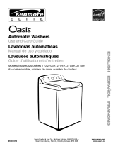
Typical exhaust installations
Typical installations vent the dryer from rear of the laundry center.
Other installations are possible.
11 4
¸¸¸¸¸¸¸¸¸¸¸¸¸¸¸¸6
2
1. Dryer 5. Elbow
2. Heavy metal vent 6. Duct tape & clamps
3. Duct tape & clamps 7. Elbow
4. Watt 8. Exhaust hood
Optional exhaust installations
This laundry center can be converted to exhaust out the right or
left side. To convert the laundry center, use Side Exhaust Kit Part
Number 279823. If your laundry center was previously exhausted
from the right or left side, it can be converted to rear exhaust by
using standard offset connections. To cover the hole in the side,
one of the following plugs can be added:
692790 (white)
3979370 (graphite)
3977784 (biscuit)
Follow the instructions in the kit to install. Kits are available from
your local Sears store or Sears Service Center.
2
1. Standard rear offset exhaust installation
2. Rear exhaust for offset close clearance connection
3. Left or right side exhaust installation
15

Alternate installations for close clearances
Venting systems come in many varieties. Select the type best for
your installation. Three close-clearance installations are shown.
Refer to the manufacturer's instructions provided with the vent
system.
2
!. Loop system with standard elbows
2, Loop system with one offset & one stardard elbow
3. Vent system with one periscope [2 in. (5 cm) clearance]
NOTE: The following kits for close clearance alternate
installations are available for purchase. To order, please reference
the service numbers located on the back page of this manual.
• Over-The-Top Installation:
Part Number 26-49900
Periscope Installation (For use with dryer vent to wall vent
mismatch):
Part Number 26-49901 - Less than 5 in. (12.7 cm) mismatch
Part Number 26-49908 - 5 in. (12.7 cm) to 18 in. (45.7 cm)
mismatch
Part Number 26-49904 - 18 in. (45.7 cm) to 29 in. (73.7 cm)
mismatch
Part Number 26-49905 - 29 in. (73.7 cm) to 50 in. (127 cm)
mismatch
Special provisions for mobile home installations
The exhaust vent must be securely fastened to anoncombustible
portion of the mobile home structure. Do not use screws or other
fastening devices that extend into the interior of the vent to
secure vent.
Determine Vent Length
1o Select the route that will provide the straightest and most
direct path outdoors. Plan the installation to use the fewest
number of elbows and turns. When using elbows or making
turns, allow as much room as possible. Bend vent gradually
to avoid kinking. Avoid 90° turns.
jj
2. Determine vent length.
The maximum length of the exhaust system depends upon:
• The type of vent (rigid metal or flexible metal).
• The number of elbows used.
• Type of hood.
Recommended hood styles are shown here.
1
(1o.2 cm)
1.Louvered hood style
2. Box hood style
The angled hood style (shown following) is acceptable.
2.5"
See the exhaust vent length chart that matches your hood
type for the maximum vent lengths you can use.
Exhaust systems longer than specified will:
• Shorten the life of the dryer.
• Reduce performance, resulting in longer drying times and
increased energy usage.
Terminate the exhaust vent outside. The exhaust vent must not
terminate beneath the mobile home and must not be connected
to any other duct, vent or chimney.
16

3. Determine the number of elbows you will need.
IMPORTANT: Do not use vent runs longer than those
specified in Vent Length Chart.
In the column listing the type of metal vent you are using
(rigid metal or flexible metal); find the maximum length of
metal vent on the same line as the number of elbows.
No. of Type of Vent Box or Angled
90° turns Louvered hoods
or elbows hoods
O Rigid metal 40 ft (12.2 m) 35 ft (10.7 m)
Flexible metal 25 ft (7.6 m) 20 ft (6.1 m)
1 Rigid metal 32 ft (9.7 m) 27 ft (8.2 m)
Flexible metal 21 ft (6.4 m) 16 ft (4.9 m)
2 Rigid metal 24 ft (7.3 m) 19 ft (5.6 m)
Flexible metal 15 ft (4.6 m) 10 ft (3.0 m)
NOTE: Side exhaust adds a 90 °turn inside the laundry center. To
determine maximum exhaust length, add 1 90° turn to the chart.
Properly leveling your laundry center prevents excessive noise
and vibration.
1. Check the levelness of the laundry center by placing a level
on the top edge of the washer, first side-to-side, then front-
to-back.
2. If the laundry center is not level, prop up the front with the
wood block and adjust the feet up or down as necessary.
Remove wood block.
1. (Optional) Put on safety glasses and gloves.
2. Install exhaust hood. Use caulking compound to seal exterior
wall opening around exhaust hood.
3. Connect vent to exhaust hood. Vent must fit inside exhaust
hood. Secure vent to exhaust hood with 4 in. (10.2 cm)
clamp.
4. Run vent to dryer location. Use the straightest path possible
(see "Determine Vent Length"). Avoid 90° turns. Use duct
tape to seal all joints.
3.
4.
Tilt the laundry center forward until the rear of the laundry
center is at least 4 in. (10.2 cm) off the floor. You may hear the
self-adjusting rear feet click into place. Lower the laundry
center to the floor. Check the levelness of the laundry center
with a level as shown above.
If laundry center will not level, recheck rear leveling legs for
free movement as described in the "Install Leveling Legs"
section. Repeat until the laundry center is level.
NOTE: It may be necessary to level the dryer again after it is
moved into its final position.
After the laundry center is in the final location and level, use
an adjustable or open-end wrench to turn the nuts on the
front feet tightly against the washer cabinet.
If the nuts are not tight against the washer cabinet, the
laundry center may vibrate.
17

1. Using a 4 in. (10.2 cm) clamp, connect vent to exhaust outlet
in laundry center. If connecting to existing vent, make sure
the vent is clean. The vent must fit over the exhaust outlet
and inside the exhaust hood. Make sure the vent is secured
to exhaust hood with a 4 in. (10.2 cm) clamp.
2. Move laundry center into final position. Do not crush or kink
vent. Make sure laundry center is level.
1. Check to be sure all parts are now installed. If there is an
extra part, go back through the steps to see which step was
skipped.
2. Check to be sure you have all of your tools.
3. Dispose/recycle all packaging materials. Keep the plastic
foam for use if the laundry center should be transported.
4. Check the laundry center's final location. Be sure the vent is
not crushed or kinked.
5. Check to be sure the laundry center is level and front leveling
feet are tight. See "Level Laundry Center."
6. Plug into a grounded outlet. Turn power on.
7. Check to be sure the water faucets are on.
8. Check for leaks around faucets and inlet hoses.
9. Remove the blue protective film on the console and any tape
remaining on the laundry center.
10. Read "Washer Use" and "Dryer Use."
11. Wipe the dryer drum interior thoroughly with a damp cloth to
remove any dust.
12. To test the washer, measure 1/2the normal recommended
amount of detergent and pour it into the washer. Close the lid.
Select HEAVY DUTY and pull out the Cycle Control knob.
Allow the washer to complete one whole cycle.
13. To test the dryer, set the dryer on a full heat cycle (not an air
cycle) for 20 minutes and start the dryer.
If the dryer will not start, check the following:
• Controls are set in a running or "On" position.
• Start button has been firmly pushed.
• Laundry Center is plugged into a grounded outlet.
• Electrical supply is connected.
• House fuse is intact and tight; or circuit breaker has not
tripped.
• Dryer door is closed.
14. When the dryer has been running for 5 minutes, open the
dryer door and feel for heat.
If you do not feel heat, turn the dryer off and check the
following:
There may be 2 fuses or circuit breakers for the dryer.
Check to make sure both fuses are intact and tight, or
that both circuit breakers have not tripped. If there is still
no heat, contact a qualified technician.
NOTE: You may notice a burning odor when dryer is first heated.
This odor is common when the heating element is first used. The
odor will go away.
FEATURES AND
BENEFITS
The DUAL-ACTION TM Plus Agitator is a uniquely designed
agitator that helps push clothes that are on top down to the
bottom of the washer where the best cleaning action takes place.
The Auto Temp Control electronically senses and maintains a
uniform water temperature by regulating incoming hot and cold
water. This helps to ensure consistant cleaning results.
WRINKLE GUARD'*' II helps keep your permanent press items
wrinkle free. When you don't unload your dryer promptly at the
end of the automatic cycle, WRINKLE GUARD ®II periodically
tumbles the load without heat.
The TUMBLE FREETM Heated Dryer Rack is used to dry items
you do not want to tumble dry, such as sweaters. The heated air
inside the dryer flows in a concentrated pattern to allow efficient
and uniform drying.
Dryness is determined by an electronic sensor the "feels" the
amount of moisture in clothes as they pass over it. When sensor
no longer detects moisture in the clothes the dryer automatically
goes into a cool down period.
Durable finish resists scratching, staining and odors for long-
lasting quality. Fabrics are protected by the smooth wash basket.
The Three-Speed Motor gently cares for a large range of fabrics
from the finest lingerie to the heaviest denims.
18

WASHER USE
f
WA1ERTEMP WATERLEVEL
HEAVYDUTY NORMAL
SHORT _ COW MEDIUM LOAD
REeULAR / W_qM CC_e
HAND _W_qM
WASHABLE$
,SHOm"
DEUEATE PERMANENTPRESS
3. Pour measured liquid chlorine bleach into the liquid chlorine
bleach dispenser, if needed. Bleach is diluted and
automatically dispensed at the proper time during the wash
cycle.
Fire Hazard
Never place items in the washer that are
dampened with gasoline or other flammable
fluids.
No washer can completely remove oil.
Do not dry anything that has ever had any type of
oil on it (including cooking oils).
Doing so can result in death, explosion, or fire.
m Do not overfill. Never use more than 1 cup (250 mL) for a
full load. Use less with a smaller load size.
n Follow the manufacturer's directions for safe use.
n To avoid spilling, use a cup with a pouring spout. Do not
let bleach splash, drip, or run down into the washer basket.
NOTE: Use only liquid chlorine bleach in this dispenser.
4. Pour measured liquid fabric softener into the fabric softener
dispenser, if desired.
The following is a guide to starting your washer. Periodic
references to other sections of this manual provide more detailed
information.
1. Pour measured powdered or liquid detergent into the washer.
If desired, add powdered or liquid color safe bleach.
2. Place a load of sorted clothes in the washer.
n
n
n
Load evenly to maintain washer balance. Mix large and
small items. See "Loading."
Items should move easily through the wash water.
Overloading can cause poor cleaning.
To reduce wrinkling of permanent press clothes and some
synthetic knits, use a large load size to provide more
space (see step 6).
Do not overfill. The dispenser holds 3 oz. (94 mL), or a capful
of fabric softener.
n Add warm water to fill the dispenser until it reaches the
crossed opening at the bottom of the funnel-shaped
portion of the dispenser.
n The fabric softener is dispensed into the first deep rinse
water automatically.
n Do not spill or drip any fabric softener on the clothes.
NOTE: Use only liquid fabric softener in this dispenser.
5. Close the washer lid.
19

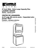
6. Turn the WATER LEVEL selector knob to the correct setting
for your wash load and the type of fabric being washed.
WAftERLEVEL
MEDIUM LOAD
7,
• Choose a load size that allows the load to move freely for
best fabric care. See "Loading."
• You may change the load size selection after the washer
has started filling by turning the selector to a different
setting.
Set the WATER TEMP selector to the correct setting for the
type of fabric and soils being washed.
WATERTEMP
This section describes the available wash cycles and will help
you make the best cycle selections for your wash loads. Each
cycle is designed for different types of fabric and soil levels.
• The washer pauses briefly throughout each cycle. These
pauses are normal. Refer to "Normal Sounds" for sounds you
may hear during a wash cycle.
• Refer to "Understanding Washer Cycles" to learn what
happens during a wash cycle.
F2ND RINSE
HEAVYDUW NORMAL
SHORT REGULAR
REGULAR SHORT
SUPER
3 QUICK
COLD AmoTR_
WARM e
COLD • •
HOT • C01.970'
COLD•
WARM ' WARM ioo*
WARM
AUTO TEMP CONTROL - Your laundry centers uses the
Auto Temp Control feature to electronically sense and
maintain a uniform water temperature by regulating
incoming hot and cold water. The cold wash is regulated
at approximately 75°F (24°C). The warm wash is
maintained at approximately 1O0°F (38°C).
Choose one of these automatic temperature control
settings to help eliminate undissolved detergent and
ensure consistent cleaning results.
Use the warmest water safe for the fabric. Follow garment
label instructions.
Selecting Water Temperatures
Water Temp Use For
Hot Whites and pastels
111°F (44°C) Heavy soils
or above
Warm Bright colors
90°-110°F Moderate to light soils
(32°-43°C)
Cold Colors that bleed or fade
70°-90°F Light soils
(21°-32°C)
NOTE: In wash water temperatures colder than 70°F (21°C),
detergents do not dissolve well. Soils can be difficult to
remove. Some fabrics can retain wear wrinkles and have
increased pilling (the formation of small lint-like balls on the
surface of garments).
8. Push in the Cycle Control knob and turn it clockwise to the
wash cycle you want. Pull out the Cycle Control knob to start
the washer.
To stop or restart your washer:
• To stop the washer at any time, push in the Cycle Control
knob.
• To restart the washer, close the lid (if open) and pull out
the Cycle Control knob.
_PfN
HAND
_8
SHORT
DELICATE PERMANENTPRESS
Heavy Duty
Use this cycle to get up to 15 minutes of wash time for sturdy or
heavily soiled loads. Wash combines high speed agitation and
high spin speeds.
• Use the Super or Regular settings for heavily soiled and
sturdy fabrics.
• Use the Short setting for light soil and delicate fabrics.
2nd Rinse
Use this cycle to add a second rinse to your wash load. This
cycle uses high-speed agitation and a high spin speed. 2nd
Rinse is also helpful for clothes that you want to rinse and spin
only.
Normal
This cycle features medium agitation for cleaning cottons and
linens, and high spin speeds to shorten drying time. For lightly
soiled cotton and linen fabrics, use the shortest time setting.
Permanent Press
Select up to 9 minutes of wash time. Wash combines fast and
slow speed agitation and slow spin speeds to reduce wrinkling.
• The Permanent Press cycle includes a load cooling
process that reduces wrinkling.
• When the timer reaches Pause, the washer will drain and
pause for approximately 2 minutes while some of the
wash water is drained and replaced with rinse water.
Delicate
The cycle features low-speed agitation for gentle soil removal
from delicate items. Low spin speeds minimize wrinkling. Use
this cycle to clean lightly to moderately soiled loads.
Hand Washables
This cycle features a series of brief, low speed agitations and
short soaks to gently clean special-care items. Low spin speeds
minimize wrinkling. Wash small loads. If items appear to be
floating (due to trapped air), stop the washer by pushing in the
Cycle Control knob. Push items down into the washer. Pull out
the Cycle Control knob to restart the washer.
20
/