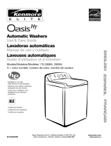
Floor drain system (view 4)
The floor drain system requires a siphon break that may be
purchased separately. See "Alternate Parts."
The siphon break must be a minimum of 28 in. (71 cm) from the
bottom of the washer. Additional hoses might be needed.
It isyour responsibility
• Tocontact a qualified electrical installer.
• To be sure that the electrical connection is adequate and in
conformance with the National Electrical Code, ANSl/NFPA
70-latest edition and all local codes and ordinances.
A copy of the above code standards can be obtained from:
National Fire Protection Association, One Batterymarch Park,
Quincy, MA 02269.
• To supply the required 3 or 4 wire, single phase, 120/240-volt,
60-Hz., AC-only electrical supply (or 3 or 4wire, 120/208-volt
electrical supply, if specified on the serial/rating plate) on a
separate 30-ampere circuit, fused on both sides of the line. A
time-delay fuse or circuit breaker is recommended. Connect
to an individual branch circuit. Do not have a fuse in the
neutral or grounding circuit.
• Do not use an extension cord.
• If codes permit and a separate ground wire is used, it is
recommended that a qualified electrician determine that the
ground path is adequate.
Electrical Connection
To properly install your laundry center, you must determine the
type of electrical connection you will be using and follow the
instructions provided for it here.
• If local codes do not permit the connection of a cabinet
ground connector to the neutral wire, see "Optional 3-wire
Connection."
• This laundry center is manufactured with a 3-wire, cabinet-
ground conductor connected to the NEUTRAL (white or
center wire) of the wiring harness at the terminal block.
• Use a 4-wire conductor cord when the laundry center is
installed in a mobile home or an area where local codes do
not permit grounding through the neutral.
If using a power supply cord:
• Use a UL listed power supply cord kit marked for use with
clothes dryers. The kit should contain:
• A UL listed 30 amp power supply cord, rated 120/240 volt
minimum. The cord should be type SRD or SRDT and be at
least 4 ft (1.22 m) long. The wires that connect to the dryer
must end in ring terminals or spade terminals with upturned
ends.
• A UL listed strain relief.
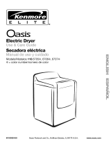
If your outlet looks like this:
©
4-wire receptacle (14-30Ft)
Then choose a 4-wire power supply cord with ring or spade
terminals and UL listed strain relief. The 4-wire power supply
cord, at least 4 ft (1.22 m) long, must have 4, 10-gauge solid
copper wires and match a 4-wire receptacle of NEMA Type
14-30R. The ground wire (ground conductor) may be either green
or bare. The neutral conductor must be identified by a white
cover.
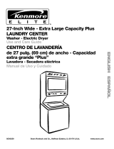
If your outlet looks like this:
©
3-wire receptacle (10-30Ft)
Then choose a 3-wire power supply cord with ring or spade
terminals and UL listed strain relief. The 3-wire power supply
cord, at least 4 ft (1.22 m) long, must have 3, 10-gauge solid
copper wires and match a 3-wire receptacle of NEMA Type
10-30R.
If connecting by direct wire:
Power supply cable must match power supply (4-wire or 3-wire)
and be:
• Flexible armored cable or nonmetallic sheathed copper cable
(with ground wire), protected with flexible metallic conduit. All
current-carrying wires must be insulated.
• 10-gauge solid copper wire. (Do not use aluminum.)
• At least 5 ft (1.52 m) long.
GROUNDING INSTRUCTIONS
• For a grounded, cord-connected washer/dryer:
This washer/dryer must be grounded. In the event of malfunc-
tion or breakdown, grounding will reduce the risk of electric
shock by providing a path of least resistance for electric
current. This washer/dryer uses a cord having an equipment-
grounding conductor and a grounding plug. The plug must be
plugged into an appropriate outlet that is properly installed and
grounded in accordance with all local codes and ordinances.
• For a permanently connected washer/dryer:
This washer/dryer must be connected to a grounded metal,
_ermanent wiring system, or an equipment-grounding con-
ductor must be run with the circuit conductors and connected
to the equipment-grounding terminal or lead on the
washer/dryer.
WARNING: Improper connection of the equipment-
grounding conductor can result in a risk of electric shock.
3heck with a qualified electrician or service representative or
_ersonnel if you are in doubt as to whether the washer/dryer
properly grounded. Do not modify the plug on the power
supply cord: if it will net fit the outlet, have a proper outlet in-
stalled by a qualified electrician.
SAVE THESE INSTRUCTIONS
4