Page is loading ...
29IN.(73.7CM)ELECTRICDRYERINSTALLATION
INSTRUCTIONS
INSTRUCCIONESDEINSTALACIONPARALASECADORA
ELECTRICADE29PULG.(73,7CM)
Table of Contents / Indice
DRYER SAFETY ............................................... 1
INSTALLATION INSTRUCTIONS .................... 2
Tools and Parts ............................................. 2
Location Requirements ................................ 2
Electrical Requirements ................................ 3
Electrical Connection .................................... 4
Venting Requirements ................................... 8
Plan Vent System .......................................... 8
Install Vent System ...................................... 10
Install Leveling Legs .................................... 10
Level Dryer................................................... 10
Connect Vent ............................................... 10
Reverse Door Swing .................................... 10
Complete Installation .................................. 11
SEGURIDAD DE LA SECADORA ................. 12
INSTRUCCIONES DE INSTALACION .......... 12
Herramientas y piezas ................. 12
Requisitos de Iocalizaci6n ......................... 12
Requisitos el_ctricos ................................... 13
Conexi6n el_ctrica ...................................... 15
Requis[tos de ventilaci6n ............................ 19
Planificaci6n del sistema de ventilaci6n ..._ 20
Instalaci6n dei sistema de ventilaci6n ........ 22
Instalaci6n de las patas niveladoras ........... 22
Nivelaci6n de la secadora ........................... 22
Conexi6n del ducto de escape ................... 22
C6mo invertir el cierre de la puerta ............. 23
Complete la instalaci6n ............................... 24
DRYERSAFETY
Your safety and the safety of others are very important.
We have provided many important safety messages in this manual and on your appliance. Always read and obey all safety
messages.
This is the safety alert symbol.
This symbol alerts you to potential hazards that can kill or hurt you and others.
All safety messages will follow the safety alert symbol and either the word "DANGER" or "WARNING."
These words mean:
You can be killed or seriously injured if you don't immediately
follow instructions,
You can be killed or seriously injured if you don't follow
instructions,
All safety messages will tell you what the potential hazard is, tell you how to reduce the chance of injury, and tell you what can
happen if the instructions are not followed.
8535829
INST.MAATION STRUCTIONS
Check that you have everything necessary for correct installation.
Proper installation is your responsibility.
Flat-blade screwdriver
Adjustable wrench that
opens to 1 in. or hax-
head socket wrench (for
adjusting dryer feet)
#2 Phillips screwdriver
Tin snips (new vent
installations)
• Level
• Safety glasses
• Caulking gun and
compound (for installing
new exhaust vent)
• Gloves
• Wire stripper (direct wire
installations)
Parts supplied:
Remove parts package from dryer drum. Check that all parts were
included.
4 leveling legs
Parts needed:
Check local codes. Check existing electrical supply and venting
and see "Electrical Requirements" and "Venting Requirements"
before purchasing parts.
Mobile home installations require metal exhaust system hardware
available for purchase from the dealer from whom you purchased
your dryer. For further information, please reference the "Service
or Assistance" section of your "Dryer User Instructions."
Explosion Hazard
Keep flammable materials and vapors, such as
gasoline, away from dryer.
Place dryer at least 18 inches (46 cm) above the floor
for a garage installation.
Failure to do so can result in death, explosion, or fire.
You will need
• A location that allows for proper exhaust installation. See
"Venting Requirements."
• A separate 30 amp circuit.
• A grounded electrical outlet located within 2 ft (61 cm) of
either side of the dryer. See "Electrical Requirements."
• A sturdy floor to support the total weight (dryer and load) of
200 Ib (90.7 kg).
• A level floor with a maximum slope of 1 in. (2.5 cm) under
entire dryer. (If slope is greater than 1 in. [2.5 cm], install
Extended Dryer Feet Kit, Part No. 279810.) Clothes may not
tumble properly and models with automatic sensor cycles
may not operate correctly if dryer is not level.
Do not operate your dryer at temperatures below 45°F (7°C). At
lower temperatures, the dryer might not shut off at the end of an
automatic cycle. Drying times can be extended.
Install the dryer where it is protected from water and/or weather.
Check code requirements. Some codes limit, or do not permit,
installation of the dryer in garages, closets, mobile homes, or
sleeping quarters. Contact your local building inspector.
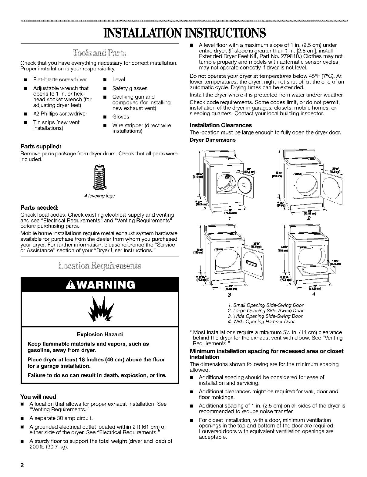
Installation Clearances
The location must be large enough to fully open the dryer door.
Dryer Dimensions
1 2
J
4
1. Small Opening Side-Swing Door
2. Large Opening Side-Swing Door
3. Wide Opening Side-Swing Door
4. Wide Opening Hamper Door
* Most installations require a minimum 51/;,in. (14 cm) clearance
behind the dryer for the exhaust vent with elbow, See "Venting
Requirements."
Minimum installation spacing for recessed area or closet
installation
The dimensions shown following are for the minimum spacing
allowed.
• Additional spacing should be considered for ease of
installation and servicing.
Additional clearances might be required for wall, door and
floor moldings.
Additional spacing of 1 in. (2.5 cm) on all sides of the dryer is
recommended to reduce noise transfer.
For closet installation, with a door, minimum ventilation
openings in the top and bottom of the door are required.
Louvered doors with equivalent ventilation openings are
acceptable.
2
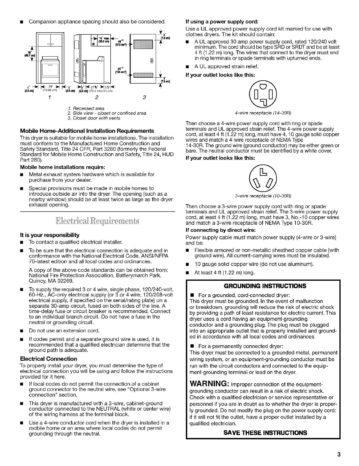
• Companion appliance spacing should also be considered.
_L
m
m
' _ _3ZZ_ _' _lr'_=7_ _15_
_.5=n) (2_) (2_) (70s cm)(14 cm)
1 2
14 ma_
{310a'n=) '
24 ,,I
3
_3,,
1. Recessed area
2. Side view - closet or confined area
3. Closet door with vents
Mobile Home-Additional Installation Requirements
This dryer is suitable for mobile home installations. The installation
must conform to the Manufactured Home Construction and
Safety Standard, Title 24 CFR, Part 3280 (formerly the Federal
Standard for Mobile Home Construction and Safety, Title 24, HUD
Part 280).
Mobile home installations require:
• Metal exhaust system hardware which is available for
purchase from your dealer.
Special provisions must be made in mobile homes to
introduce outside air into the dryer. The opening (such as a
nearby window) should be at least twice as large as the dryer
exhaust opening.
It is your responsibility
• Tocontact a qualified electrical installer.
• To be sure that the electrical connection is adequate and in
conformance with the National Electrical Code, ANSl/NFPA
70-latest edition and all local codes and ordinances.
A copy of the above code standards can be obtained from:
National Fire Protection Association, Batterymarch Park,
Quincy, MA 02269.
• To supply the required 3 or 4 wire, single phase, 120/240-volt,
60-Hz., AC-only electrical supply (or 3 or 4 wire, 120/208-volt
electrical supply, if specified on the serial/rating plate) on a
separate 30-amp circuit, fused on both sides of the line. A
time-delay fuse or circuit breaker is recommended. Connect
to an individual branch circuit. Do not have a fuse in the
neutral or grounding circuit.
• Do not use an extension cord.
• If codes permit and a separate ground wire is used, it is
recommended that a qualified electrician determine that the
ground path is adequate.
Electrical Connection
To properly install your dryer, you must determine the type of
electrical connection you will be using and follow the instructions
provided for it here.
• If local codes do not permit the connection of a cabinet
ground connector to the neutral wire, see "Optional 3-wire
connection" section.
• This dryer is manufactured with a 3-wire, cabinet-ground
conductor connected to the NEUTRAL (white or center wire)
of the wiring harness at the terminal block.
• Use a 4-wire conductor cord when the dryer is installed in a
mobile home or an area where local codes do not permit
grounding through the neutral.
If using a power supply cord:
Use a UL approved power supply cord kit marked for use with
clothes dryers. The kit should contain:
• A UL approved 30 amp power supply cord, rated 120/240 volt
minimum. The cord should be type SRD or SRDT and be at least
4 ft (1.22 m) long. The wires that connect to the dryer must end
in ring terminals or spade terminals with upturned ends.
• A ULapproved strain relief.
If your outlet looks like this:
©
4-wire receptacle (14-30R)
Then choose a 4-wire power supply cord with ring or spade
terminals and UL approved strain relief. The 4-wire power supply
cord, at least 4 ft (1.22 m)long, must have 4, 10 gauge solid copper
wires and match a 4-wire receptacle of NEMA Type
14-30R. The ground wire (ground conductor) may be either green or
bare. The neutral conductor must be identified by a white cover.
If your outlet looks like this:
©
3-wire receptacle (10-30R)
Then choose a 3-wire power supply cord with ring or spade
terminals and UL approved strain relief. The 3-wire power supply
cord, at least 4 ft (1.22 m) long, must have 3, No.-10 copper wires
and match a 3-wire receptacle of NEMA Type 18-30R.
If connecting by direct wire:
Power supply cable must match power supply (4-wire or 3-wire)
and be:
• Flexible armored or non-metallic sheathed copper cable (with
ground wire). All current-carrying wires must be insulated.
• 10 gauge solid copper wire (do not use aluminum).
• At least 4 ft (1.22 m) long.
GROUNDING INSTRUCTIONS
• For a grounded, cord-connected dryer:
This dryer must be grounded. In the event of malfunction
or breakdown, grounding will reduce the risk of electric shock
by providing a path of least resistance for electric current. This
dryer uses a cord having an equipment-grounding
conductor and a grounding plug. The plug must be plugged
into an appropriate outlet that is properly installed and ground-
ed in accordance with all local codes and ordinances.
• For a permanently connected dryer:
This dryer must be connected to a grounded metal, permanent
wtring system, or an equipment-grounding conductor must be
run with the circuit conductors and connected to the equip-
ment-grounding terminal or lead on the dryer.
WARNING: Improper connection of the equipment-
grounding conductor can result in a risk of electric shock.
;heck with a qualified electrician or service representative or
)ersonnel if you are in doubt as to whether the dryer is proper-
grounded. Do not modify the plug on the power supply cord:
if it will not fit the outlet, have a proper outlet installed by a
qualified electrician.
SAVE THESE INSTRUCTIONS
PowerSupplyCord DirectWire
FireHazard
Useanew UL approved 30 amp power supply cord.
Use a UL approved strain relief.
Disconnect power before making electrical connections.
Connect neutral wire (white or center wire) to center
terminal (silver).
Ground wire (green or bare wire) must be connected to
green ground connector.
Connect remaining 2 supply wires to remaining
2 terminals (gold).
Securely tighten all electrical connections.
Failure to do so can result in death, fire, or
electrical shock.
Fire Hazard
Use 10 gauge solid copper wire.
Use a UL approved strain relief.
Disconnect power before making electrical connections.
Connect neutral wire (white or center wire) to center
terminal (silver).
Ground wire (green or bare wire) must be connected to
green ground connector.
Connect remaining 2 supply wires to remaining
2 terminals (gold).
Securely tighten all electrical connections.
Failure to do so can result in death, fire, or
electrical shock.
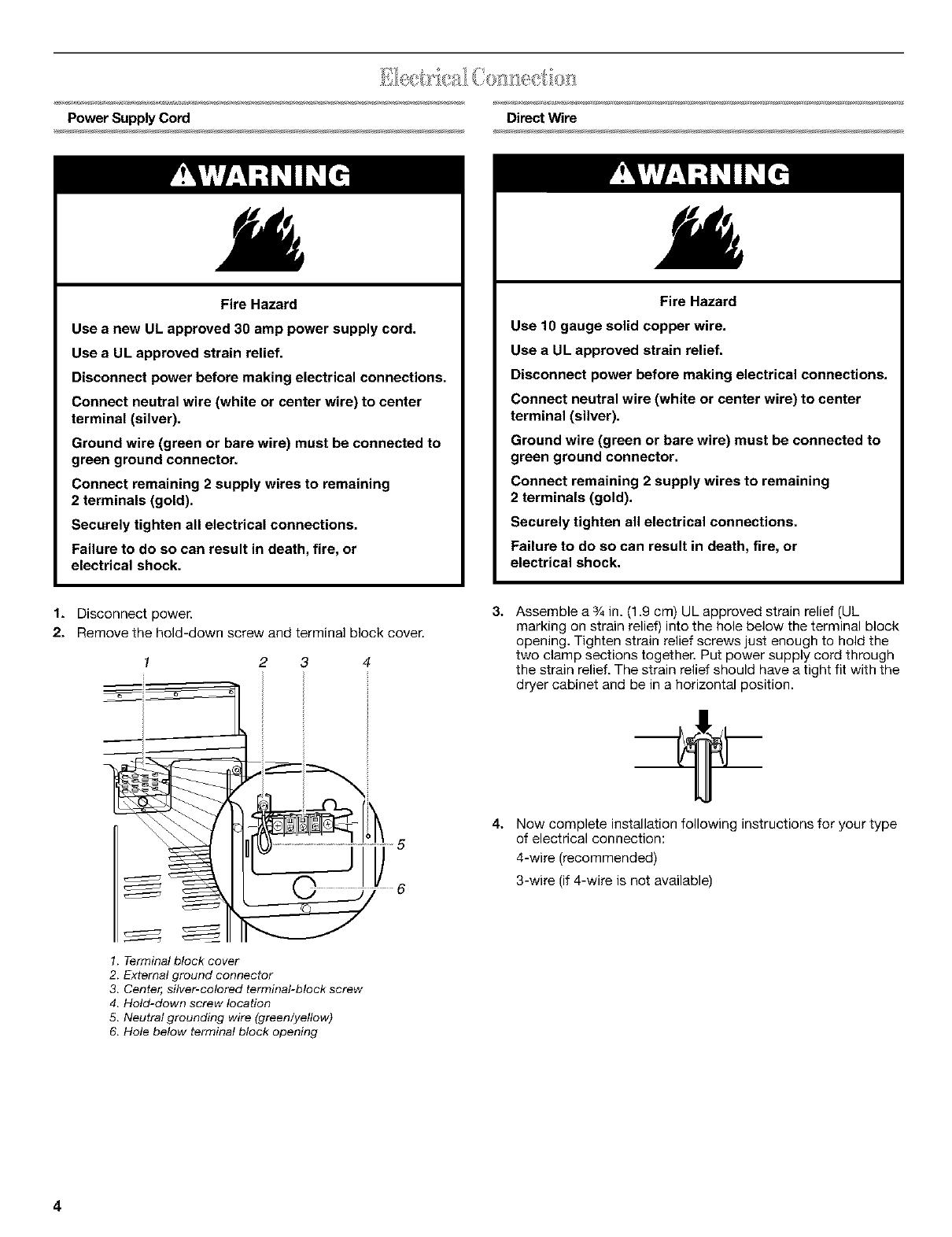
1. Disconnect power.
2. Remove the hold-down screw and terminal block cover.
1. Terminal block cover
2. External ground connector
3. Center, silver-colored terminal-block screw
4. Hold-down screw location
5. Neutral grounding wire (green/yellow)
6. Hole below terminal block opening
3.
4.
Assemble a 3/4in. (1.9 cm) UL approved strain relief (UL
marking on strain relief) into the hole below the terminal block
opening, Tighten strain relief screws just enough to hold the
two clamp sections together, Put power supply cord through
the strain relief. The strain relief should have a tight fit with the
dryer cabinet and be in a horizontal position.
Now complete installation following instructions for your type
of electrical connection:
4-wire (recommended)
3-wire (if 4-wire is not available)
4

Electrical Connection Options 1.
_JJJJJJJJ__,s_,__ 2.
If your home has: And you will be Go to Section
connecting to:
4-wire receptacle A UL listed, 120/ 4-wire connection:
(NEMA Type 14-30R) 240 volt Power Supply
(_ minimum, 30 Cord
amp., dryer
power supply
cord*
4-wire direct A fused 4-wire connection:
disconnect or Direct Wire
circuit breaker
/,_'_ box*
3-wire receptacle A UL listed, 120/ 3-wire connection:
(NEMA type 10-30R) 240 volt Power Supply
(_ minimum, 30 Cord
amp., dryer
power supply
cord*
3-wire direct A fused 3-wire connection:
disconnect or Direct Wire
circuit breaker
box*
*If local codes do not permit the connection of a frame-grounding
conductor to the neutral wire, go to "Optional 3-wire connection"
section.
4-wire connection: Power Supply Cord
IMPORTANT: A 4-wire connection is required for mobile homes
and where local codes do not permit the use of 3-wire
connections.
2 6
5 7
1.4-wire receptacle (NEMA type 14-30R)
2. 4-prong plug
3. Ground prong
4. Neutral prong
5. Spade terminals with upturned ends
6. 3/_in, (1.9 cm) UL approved strain relief
7. Ring terminals
Remove center terminal block screw.
Remove appliance ground wire (green with yellow stripes)
from external ground connector screw. Fasten it under center,
silver colored terminal block screw.
1
--.. i
9
2
3
1. External ground connector- Dotted line shows
position of NEUTRAL ground wire before being
moved to center terminal block screw
2. Center silver-colored terminal block screw
3. Green/yellow wire of harness
3. Connect ground wire (green or bare) of power supply cord to
external ground conductor screw. Tighten screw.
4. Connect neutral wire (white or center wire) of power supply
cord under center screw of the terminal block.
3
4
6
1. ¾in. (1.9 cm) UL-listed strain relief
2. Green wire of power supply cord or bare copper wire
3. External ground connector
4. Center silver-colored terminal block screw
5, Neutral wire (white or center)
6. Neutral grounding wire (green/yellow)
5. Connect the other wires to outer terminal block screws.
Tighten screws.
6. Tighten strain relief screws.
7. Insert tab of terminal block cover into slot of dryer rear panel.
Secure cover with hold-down screw.
4-wireconnection: Direct Wire
IMPORTANT: A 4-wire connection is required for mobile homes
and where local codes do not permit the use of 3-wire
connections.
Direct wire cable must have 5 ft (1.52 m) of extra length so dryer
can be moved if needed.
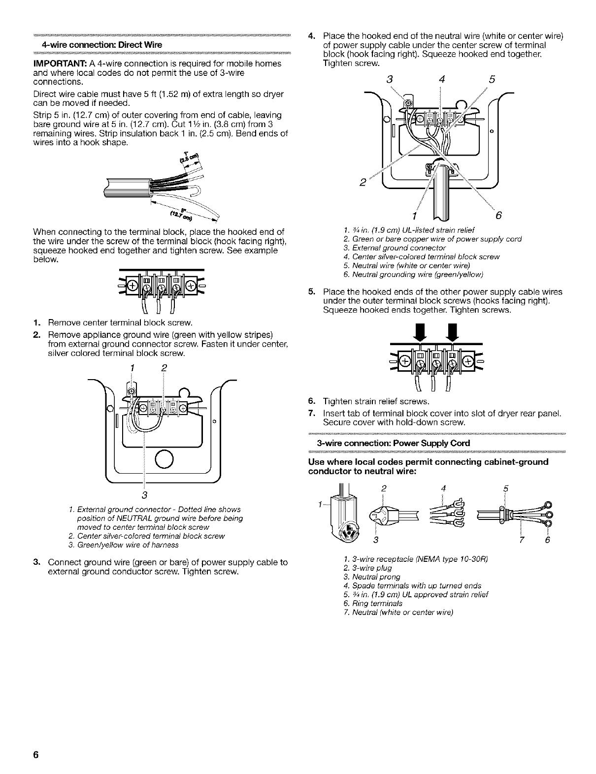
Strip 5 in. (12.7 cm) of outer covering from end of cable, leaving
bare ground wire at 5 in. (12.7 cm). Cut 11_,in. (3.8 cm) from 3
remaining wires. Strip insulation back 1 in. (2.5 cm). Bend ends of
wires into a hook shape.
When connecting to the terminal block, place the hooked end of
the wire under the screw of the terminal block (hook facing right),
squeeze hooked end together and tighten screw. See example
below.
1. Remove center terminal block screw.
2. Remove appliance ground wire (green with yellow stripes)
from external ground connector screw. Fasten it under center,
silver colored terminal block screw.
3
2
f
o
)
3
1. External ground connector- Dotted line shows
position of NEUTRAL ground wire before being
moved to center terminal block screw
2. Center silver-colored terminal block screw
3. Green/yellow wire of harness
3. Connect ground wire (green or bare) of power supply cable to
external ground conductor screw. Tighten screw.
4.
Place the hooked end of the neutral wire (white or center wire)
of power supply cable under the center screw of terminal
block (hook facing right). Squeeze hooked end together.
Tighten screw.
2
3 4 5
6
r
1. ¾ in (!.9 cm) UL-listed strain relief
2. Green or bare copper wire of power supply cord
3. External ground connector
4. Center silver-colored terminal block screw
5. Neutral wire (white or center wire)
6. Neutral grounding wire (green/yellow)
5. Place the hooked ends of the other power supply cable wires
under the outer terminal block screws (hooks facing right).
Squeeze hooked ends together. Tighten screws.
!! !!
6. Tighten strain relief screws.
7. Insert tab of terminal block cover into slot of dryer rear panel.
Secure cover with hold-down screw.
3-wire connection: Power Supply Cord
Use where local codes permit connecting cabinet-ground
conductor to neutral wire:
2 4 5
3 7 6
1.3-wire receptacle (NEMA type 10-30R)
2. 3-wire plug
3. Neutral prong
4. Spade terminals with up turned ends
5. _ in. (!.9 cm) UL approved strain relief
6. Ring terminals
7. Neutral (white or center wire)
6
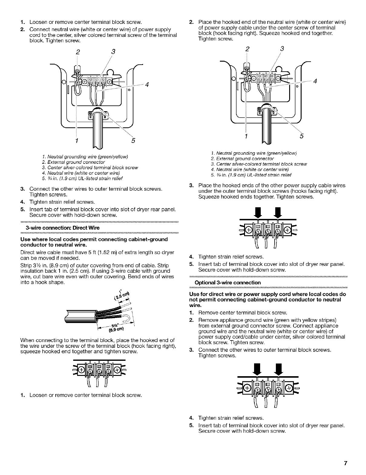
1. Loosen or remove center terminal block screw.
2. Connect neutral wire (white or center wire) of power supply
cord to the center, silver colored terminal screw of the terminal
block. Tighten screw.
2 3
5
1. Neutral grounding wire (green/yellow)
2. External ground connector
3. Center silver-colored terminal block screw
4. Neutral wire (white or center wire)
5. _ in. (!.9 cm) UL-listed strain relief
3. Connect the other wires to outer terminal block screws.
Tighten screws.
4. Tighten strain relief screws.
5. Insert tab of terminal block cover into slot of dryer rear panel.
Secure cover with hold-down screw.
3-wire connection: Direct Wire
Use where local codes permit connecting cabinet-ground
conductor to neutral wire.
Direct wire cable must have 5 ft (1.82 m) of extra length so dryer
can be moved if needed.
Strip 31/2in. (8.9 cm) of outer covering from end of cable. Strip
insulation back 1 in. (2.5 cm). If using 3-wire cable with ground
wire, cut bare wire even with outer covering. Bend ends of wires
into a hook shape.
When connecting to the terminal block, place the hooked end of
the wire under the screw of the terminal block (hook facing right),
squeeze hooked end together and tighten screw.
1. Loosen or remove center terminal block screw.
2J
Place the hooked end of the neutral wire (white or center wire)
of power supply cable under the center screw of terminal
block (hook facing right). Squeeze hooked end together.
Tighten screw.
2 3
5
31
1. Neutral grounding wire (green/yellow)
2. External ground connector
3. Center silver-colored terminal block screw
4. Neutral wire (white or center wire)
5. _ in. (!.9 cm) UL-listed strain relief
Place the hooked ends of the other power supply cable wires
under the outer terminal block screws (hooks facing right).
Squeeze hooked ends together. Tighten screws.
!! !
4. Tighten strain relief screws.
5. Insert tab of terminal block cover into slot of dryer rear panel.
Secure cover with hold-down screw.
Optional 3-wire connection
Use for direct wire or power supply cord where local codes do
not permit connecting cabinet-ground conductor to neutral
wire.
1. Remove center terminal block screw.
2. Remove appliance ground wire (green with yellow stripes)
from external ground connector screw. Connect appliance
ground wire and the neutral wire (white or center wire) of
power supply cord/cable under center, silver colored terminal
block screw. Tighten screw.
3. Connect the other wires to outer terminal block screws.
Tighten screws.
I !!
4. Tighten strain relief screws.
5. Insert tab of terminal block cover into slot of dryer rear panel.
Secure cover with hold-down screw.
7

6. Connect a separate copper ground wire from the external
ground connector screw to an adequate ground.
1. External ground connector
2, Neutral grounding wire (green/yellow)
3. Neutral wire (white or center wire)
4. Grounding path determined by a qualified electrician
Fire Hazard
Use a heavy metal vent.
Do not use a plastic vent.
Do not use a metal foil vent.
Failure to follow these instructions can result in death
or fire.
WARNING: To reduce the risk of fire, this dryer MUST BE
EXHAUSTED OUTDOORS.
4 in. (10.2 cm) heavy metal exhaust vent and clamps must be
used. DURASAFE TM venting products are recommended.
DURASAFE TM vent products can be purchased from your dealer
or by calling Whirlpool Parts and Accessories. For more
information, see the "Assistance or Service" section of your
"Dryer User instructions."
• Do not exhaust the dryer into any gas vent, chimney, wail,
ceiling, or a concealed space of a building.
• Do not use an exhaust hood with a magnetic latch.
• Do not install flexible metal vent in enclosed walls, ceilings or
floors.
• Do not use screws or other fastening devices that extend into
the interior of the vent to secure vent.
IMPORTANT: Observe all governing codes and ordinances.
Improper venting can cause moisture and lint to collect
indoors, which may result in:
• Moisture damage to woodwork, furniture, paint, wall-
paper, carpets, etc.
• Housecleaning problems and health problems.
Use a heavy metal vent. Do not use plastic or metal foil vent.
Rigid metal vent is recommended to prevent crushing and kinking.
Flexible metal vent must be fully extended and supported when
the dryer is in its final position. Remove excess flexible metal vent
to avoid sagging and kinking that may result in reduced airflow
and poor performance.
An exhaust hood should cap the vent to prevent rodents and
insects from entering the home.
Exhaust hood must be at least 12 in. (30.5 cm) from the ground or
any object that may be in the path of the exhaust (such as flowers,
rocks or bushes, etc.).
If using an existing vent system, clean lint from the entire length of
the system and make sure exhaust hood is not plugged with lint.
Replace any plastic or metal foil vent with rigid metal or flexible
metal vent.
Use clamps to seal all joints. Do not use duct tape, screws or
other fastening devices that extend into the interior of the vent to
secure vent.
Typical exhaust installations
Typicalinstallationsvent the dryerfrom the rear of the dryer.
1--
2
/] k 3
•_ _.
1. Dryer
2. Elbow
3. Wall
4, Exhaust hood
5. Clamps
6. Rigid metal or flexible metal vent
7, Vent length necessary to connect elbows
8. Exhaust outlet
8
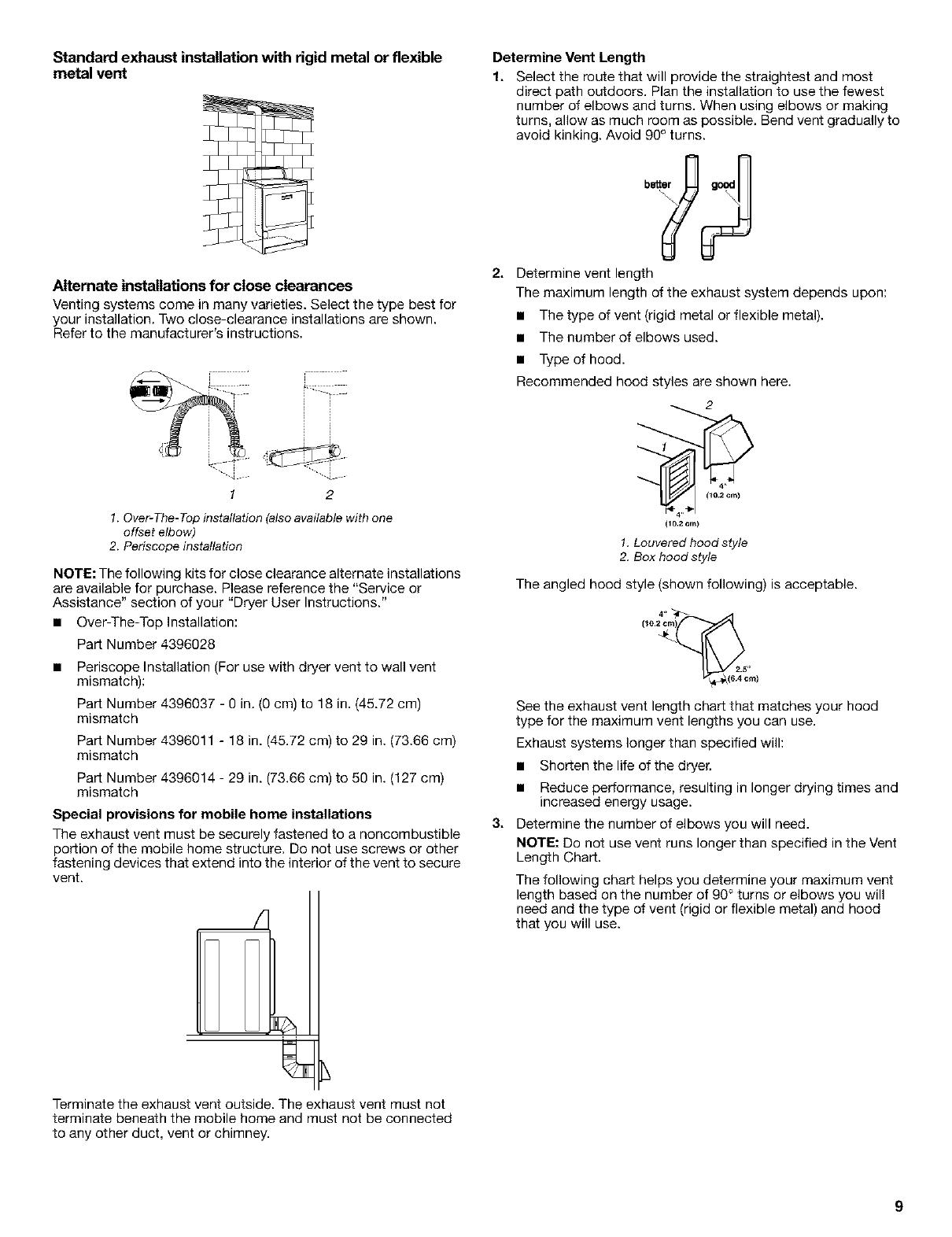
Standard exhaust installation with rigid metal or flexible
metal vent
Alternate installations for close clearances
Venting systems come in many varieties. Select the type best for
your installation. Two close-clearance installations are shown.
Refer to the manufacturer's instructions.
r -
1 2
1. Over-The-Top installation (also available with one
offset elbow)
2. Periscope installation
NOTE: The following kits for close clearance alternate installations
are available for purchase. Please reference the "Service or
Assistance" section of your "Dryer User Instructions."
• Over-The-Top Installation:
Part Number 4396028
• Periscope Installation (For use with dryer vent to wall vent
mismatch):
Part Number 4396037 - 0 in. (0 cm) to 18 in. (45.72 cm)
mismatch
Part Number 4396011 - 18 in. (45.72 cm) to 29 in. (73.66 cm)
mismatch
Part Number 4396014 - 29 in. (73.66 cm) to 50 in. (127 cm)
mismatch
Special provisions for mobile home installations
The exhaust vent must be securely fastened to a noncombustible
portion of the mobile home structure. Do not use screws or other
fastening devices that extend into the interior of the vent to secure
vent.
qh
Terminate the exhaust vent outside. The exhaust vent must not
terminate beneath the mobile home and must not be connected
to any other duct, vent or chimney.
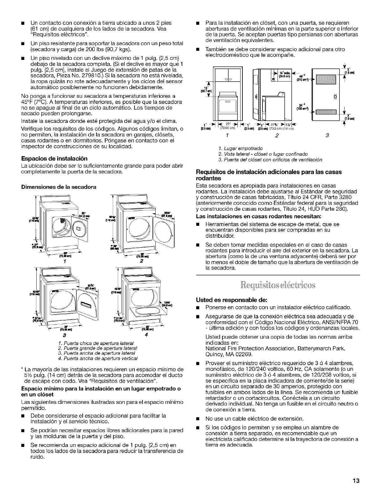
Determine Vent Length
1. Select the route that will provide the straightest and most
direct path outdoors. Plan the installation to use the fewest
number of elbows and turns. When using elbows or making
turns, allow as much room as possible. Bend vent gradually to
avoid kinking. Avoid 90° turns.
better good
?J
2. Determine vent length
The maximum length of the exhaust system depends upon:
• The type of vent (rigid metal or flexible metal).
• The number of elbows used.
• Type of hood.
Recommended hood styles are shown here.
2
(10.2 cm)
1.Louvered hood style
2. Box hood style
The angled hood style (shown following) is acceptable.
See the exhaust vent length chart that matches your hood
type for the maximum vent lengths you can use.
Exhaust systems longer than specified will:
• Shorten the life of the dryer.
• Reduce performance, resulting in longer drying times and
increased energy usage.
3. Determine the number of elbows you will need.
NOTE: Do not use vent runs longer than specified in the Vent
Length Chart.
The following chart helps you determine your maximum vent
length based on the number of 90° turns or elbows you will
need and the type of vent (rigid or flexible metal) and hood
that you will use.
9

Vent Length Chart
Number of Type of Box or Angled
90° turns vent Louvered hoods
or elbows hoods
O Rigid metal 64 ff (20 m) 58 ft (17.7 m)
Flexible metal 36 ft (11 m) 28 ft (8.5 m)
1 Rigid metal 54 ft (16.5 m) 48 ft (14.6 m)
Flexible metal 31 ft (9.4 m) 23 ft (7 m)
2 Rigid metal 44 ft (13.4 m) 38 ft (11.6 m)
Flexible metal 27 ft (8.2 m) 19 ft (5.8 m)
3 Rigid metal 35 ff (10.7 m) 29 ft (8.8 m)
Flexible metal 25 ft (7.6 m) 17 ft (5.2 m)
4 Rigid metal 27 ft (8.2 m) 21 ft (6.4 m)
Flexible metal 23 ft (7 m) 15 ft (4.6 m)
1. (Optional) Put on safety glasses and gloves.
2. Install exhaust hood. Use caulking compound to seal exterior
wall opening around exhaust hood.
3. Connect vent to exhaust hood. Vent must fit inside exhaust
hood. Secure vent to exhaust hood with 4 in. (10.2 cm) clamp.
4. Run vent to dryer location. Use the straightest path possible.
See "Determine Vent Length." Avoid 90° turns. Use clamps to
seal all joints. Do not use duct tape, screws or other fastening
devices that extend into the interior of the vent to secure vent.
5. Place a carton corner post under each of the 2 dryer back
corners. Stand the dryer up. Slide the dryer on the corner
posts until it is close to its final location.
6. Leave enough room to connect the exhaust vent.
Check the levelness of the dryer. Check levelness first
side-to-side, then front-to-back.
Ifthe dryer is not level, prop up the dryer using a wood block. Use
a wrench to adjust the legs up or down and check again for
levelness.
NOTE: It might be necessary to level the dryer again after it is
moved into its final position.
1. Using a 4 in. (10.2 cm) clamp, connect vent to exhaust outlet
in dryer. If connecting to existing vent, make sure the vent is
clean. The dryer vent must fit over the dryer exhaust outlet
and inside the exhaust hood. Make sure the vent is secured to
exhaust hood with a 4 in. (10.2 cm) clamp.
2. Move dryer into final position. Do not crush or kink vent. Make
sure dryer is level.
3. (On gas models) If flexible metal tubing is used, check to be
sure there are no kinks in the flexible gas line.
You can change your door swing from a right-side opening to a
left-side opening, if desired.
Reversible Large Side-Swing Door
1o To protect the floor, use a large flat piece of cardboard from
the dryer carton. Place cardboard under the entire back edge
of the dryer. See illustration.
2. Firmly grasp the body of the dryer (not the top or console
panel).
\ \
Gently lay the dryer on the cardboard corners.
3. Examine the leveling legs. Find the diamond marking.
1. Place towel (1) on top of dryer to protect surface.
2. Open dryer door. Remove bottom screws from cabinet side of
hinges (3). Loosen (do not remove) top screws from cabinet
side of hinges.
3. Lift door until top screws in cabinet are in large part of hinge
slot. Pull door forward off screws. Set door on top of dryer.
Remove top screws from cabinet.
4. Screw the legs into the leg holes by hand. Use a wrench to
finish turning the legs until the diamond marking is no longer
visible.
10

4. Use a small, flat-blade screwdriver to carefully remove 4 hinge 8.
hole plugs (4) on left side of cabinet. Insert plugs in hinge
holes on right side of cabinet.
5. Insert screws in bottom holes on left side of cabinet. Tighten
screws halfway. Position door so large end of door hinge slot go
is over screws. Slide door up so screws are in bottom of slots.
Tighten screws. Insert and tighten top screws in hinges.
6. Close door and check that door strike aligns with door catch
(2). If needed, slide door catch left or right within slot to adjust
alignment.
Reversible Super Wide Side-Swing Door
5
6_
3
1. Place towel (1) on top of dryer to protect surface.
2. Open dryer door. Remove bottom screws from cabinet side of
hinges (4). Loosen (do not remove) top screws from cabinet
side of hinges.
3. Lift door until top screws in cabinet are in large part of hinge
slot. Pull door forward oft screws. Set door (handle side up) on
top of dryer. Remove top screws from cabinet.
4. Remove screws attaching hinges to door.
5. Remove screws at top, bottom and side of door (4 screws).
Holding door over towel on dryer, grasp sides of outer door
and carefully lift to separate it from inner door. Do NOT pry
apart with putty knife. Do NOT pull on door seal or plastic
door catches.
6. Be careful to keep cardboard spacer centered between
doors, Reattach outer door panel to inner door panel so
handle is on the side where hinges were just removed.
7. Attach door hinges to door so large part of hinge slot is at
bottom of hinge.
Remove door strike (5)from cabinet. Use a small, flat-blade
screwdriver to carefully remove 4 hinge hole plugs (6) on left
side of cabinet. Insert plugs in hinge holes on right side of
cabinet.
Insert screws in bottom holes on left side of cabinet. Tighten
screws halfway. Position door so large end of door hinge slot
is over screws. Slide door up so screws are in bottom of slots.
Tighten screws. Insert and tighten top screws in hinges.
10. Remove door strike plug (2). Insert the door strike you
removed in Step 8 in hole and secure with screw. Insert door
strike plug in original door strike hole and secure with screw.
11. Close door and check that door strike aligns with door catch
(3). If needed, slide door catch left or right within slot to adjust
alignment.
1o Check to be sure all parts are now installed. Ifthere is an extra
part, go back through the steps to see which step was
skipped.
2. Check to be sure you have all of your tools.
3. Dispose of all packaging materials.
4. Check the dryer's final location. Be sure the vent is not
crushed or kinked.
5. Check to be sure the dryer is level. (See "Level Dryer.")
6. Plug into a grounded outlet. Turn power on.
7. Remove the blue protective film on the console and any tape
remaining on the dryer.
8. Read your"Dryer User Instructions."
g. Wipe the dryer drum interior thoroughly with a damp cloth to
remove any dust.
10. Set the dryer on a full heat cycle (not an air cycle) for 20
minutes and start the dryer.
If the dryer will not start, check the following:
• Controls are set in a running or "On" position.
• Start button has been pushed firmly.
• Dryer is plugged into a grounded outlet.
• Electrical supply is connected.
• House fuse is intact and tight; or circuit breaker has not
tripped.
• Dryer door is closed.
11. When the dryer has been running for 5 minutes, open the
dryer door and feel for heat.
If you do not feel heat, turn the dryer off and check the
following:
• There may be 2 fuses or circuit breakers for the dryer. Check
to make sure both fuses are intact and tight, or that both
circuit breakers have not tripped. If there is still no heat,
contact a qualified technician.
NOTE: You may notice a burning odor when the dryer is first
heated. This odor is common when the heating element is first
used. The odor will go away.
11

INSTRUCCIONESDE STALACION PARALASECADORA
ELECTRICADE29PULG.(73,7CM)
SEGURIDADDELASECADORA
Su seguridad y la seguridad de los demds es muy importante.
Hemos incluido muchos mensajes importantes de seguridad en este manual y en su electrodomestico. Lea y obedezca siempre
todos los mensajes de seguridad.
Este es el simbolo de advertencia de seguridad.
Este simbolo le llama la atenci6n sobre peligros potenciales que pueden ocasionar la muerte o una lesi6n a
usted y a los dem_.s.
Todos los mensajes de seguridad irAn a continuaci6n del s_mbolo de advertencia de seguridad y de la palabra
"PELIGRO" o "ADVERTENCIA". Estas palabras significan:
Si no sigue las instrucciones de inmediato, usted puede
morir o sufrir una lesi6n grave.
Si no sigue las instrucciones, usted puede morir o sufrir
una lesi6n grave.
Todos los mensajes de seguridad le dir_.n el peligro potencial, le dirAn c6mo reducir las posibilidades de sufrir una lesi6n y Io que
puede suceder si no se siguen las instrucciones.
INSTRUCCIONESDEINSTALACION
Verifique si tiene todo Io necesario para una instalaci6n correcta.
La instalaci6n adecuada es responsabilidad suya.
Destornillador de cuchilla
plana
Llave de tuercas ajustable
que se abra a 1 pulg. o
una Ilave de cubo de
cabeza hexagonal (para
regular las patas de la
secadora)
Nivel
Destornillador Phillips # 2
• Tijeras delata
(instalaciones del nuevo
conducto de ventilaci6n)
• Llentes de seguridad
• Pistolay masilla para
calafateo (para instalar el
nuevo ducto de escape)
• Guantes
• Desforrador de alambre
(instalaciones de
cableado directo)
Piezas suministradas:
Retire el paquete de piezas del tambor de la secadora. Verifique
que esten todas las piezas.
4 paras niveladoras
Las instalaciones en casas rodantes requieren herramientas del
sistema de escape de metal, que se encuentran disponibles para
ser compradas en el distribuidor donde compr6 la secadora. Para
obtener mas informaci6n, tome como referencia la secci6n
"Ayuda o servicio tecnico" de sus "lnstrucciones para el usuario
de la secadora'.
Peligro de Explosi6n
Mantenga los materiales y vapores inflamables, como
gasolina, lejos de la secadora.
Coloque la secadora a un minimo de 46 cm sobre
el piso para la instalaci6n en un garaje.
No seguir estas instrucciones puede ocasionar
la muerte, explosi6n o incendio.
Piezas para adquirir:
Verifique los c6digos locales. Verifique el suministro electrico
existente y la ventilaci6n y yea "Requisitos electricos" y
"Requisitos de ventilaci6n" antes de comprar las piezas.
Usted necesitar_
• Una Iocalizaci6n que permita una instalaci6n adecuada del
ducto de escape. Consulte "Requisitos de ventilaci6n".
• Un circuito separado de 30 amperios.
12
Un contacto con conexi6n a tierra ubicado a unos 2 pies
(61 cm) de cualquiera de los lados de la secadora. Vea
"Requisitos electricos".
Un piso resistente para soportar la secadora con un peso total
(secadora y carga) de 200 Ibs (90,7 kgs).
Un piso nivelado con un declive m_ximo de 1pulg. (2,5 cm)
debajo de la secadora completa. (Si el declive es mayor que 1
pulg. [2,5 cm], instale el Juego de extensi6n de paras de la
secadora, Pieza No. 279810.) Si la secadora no esta nivelada,
la ropa quizas no rote adecuadamente y los ciclos del sensor
automatico posiblemente no funcionen debidamente.
No ponga a funcionar su secadora a temperaturas inferiores a
45°F (7°C). A temperaturas inferiores, es posible que la secadora
no se apague al final de un ciclo automatico. Los tiempos de
secado pueden prolongarse.
Instale la secadora donde este protegida del agua y/o el clima.
Verifique los requisitos de los c6digos. Algunos c6digos limitan, o
no permiten, la instalaci6n de la secadora en garajes, cl6sets,
casas rodantes o en dormitorios. P6ngase en contacto con el
inspector de construcciones de su Iocalidad.
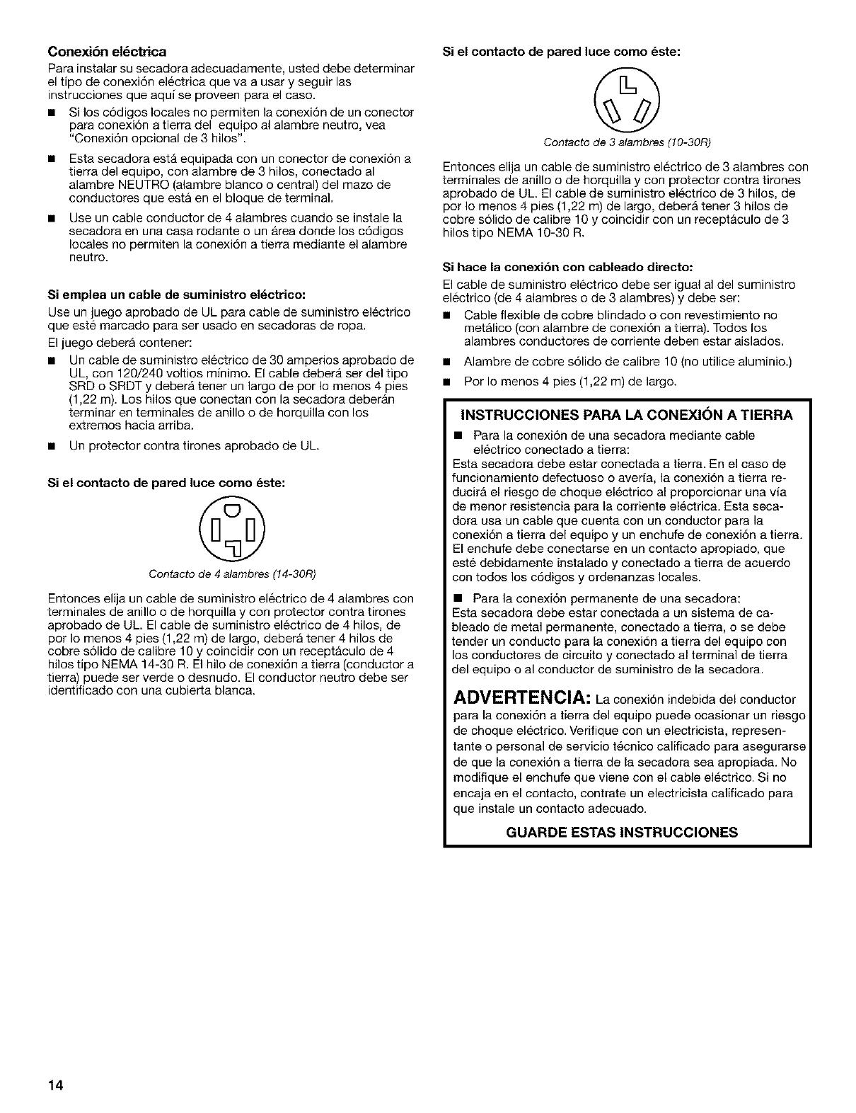
Espacios de instalacibn
La ubicaci6n debe set Io suficientemente grande para poder abrir
completamente la puer[a de la secadora.
Dimensiones de la secadora
('/0,6 m /
f
2
3
1. Puerta chica de apertura lateral
2. Puerta grande de apertura lateral
3 Puerta ancha de apertura lateral
4 Puerta ancha de apertura vertical
* La mayoria de las instalaciones requieren un espacio minimo de
51/2pulg. (14 cm) detras de la secadora para acomodar el ducto
de escape con codo. Vea "Requisitos de ventilaci6n".
Espacio minimo para la instalaci6n en un lugar empotrado o
en un clbset
Las siguientes dimensiones ilustradas son para el espacio minimo
permitido.
• Debe considerarse el espacio adicional para facilitar la
instalaci6n y el servicio tecnico.
Se podrian necesitar espacios libres adicionales para la pared
y las molduras de la puerta y del piso.
Se recomienda un espacio adicional de 1 pulg. (2,5 cm) en
todos los lados de la secadora para reducir la transferencia de
ruido.
Para la instalaci6n en cl6set, con una puer[a, se requieren
aber_uras de ventilaci6n minimas en la parle superior e inferior
de la puerta. Se aceptan puertas tipo persianas con aberturas
de ventilaci6n equivalentes.
• Tambien se debe considerar espacio adicional para otro
electrodomestico que le acompafie.
_L
m
24,,,
m
<,
(25_) (25_) (25_) (705cm)(14cm_
1 2 3
1. Lugar empotrado
2. Vista lateral - cl6set o lugar confinado
3. Puerta del cl6set con orificios de ventitacidn
Requisitos de instalacibn adicionales para las casas
rodantes
Esta secadora es apropiada para instalaciones en casas
rodantes. La instalaci6n debe ajustarse al Estb.ndar de seguridad
y construcci6n de casas fabricadas, Titulo 24 CFR, ParLe3280
(anteriormente conocido como Estandar federal para la seguridad
y construcci6n de casas rodantes, Titulo 24, HUD Parte 280).
Las instalaciones en casas rodantes necesitan:
• Herramientas del sistema de escape de metal, que se
encuentran disponibles para set compradas en su
distribuidor.
• Se deben tomar medidas especiales en el caso de casas
rodantes para introducir el aire del exterior en la secadora. La
aber_ura (como la de una ventana adyacente) debera ser por
Io menos el doble de tamafio que la abertura de ventilaci6n de
la secadora.
Usted es responsable de:
• Ponerseencontacto con un instalador electrico calificado.
• Asegurarse de que la conexi6n electrica sea adecuada y de
conformidad con el C6digo Nacional Electrico, ANSI/NFPA 70
- t]ltima edici6n y con todos los c6digos y ordenanzas locales.
Usted puede obtener una copia de todas las normas arriba
indicadas en:
National Fire Protection Association, Batterymarch Park,
Quincy, MA 02269.
Proveer el suministro electrico requerido de 3 6 4 alambres,
monofasico, de 120/240 voltios, 60 Hz, CA solamente (o un
suministro electrico de 3 6 4 alambres, de 120/208 voltios, si
se especifica en la placa indicadora de corriente/de la serie)
en un circuito separado de 30 amperios, protegido con
fusibles en ambos lados de la line& Se recomienda un fusible
retardador o un cor[acircuitos. Conectela a un circuito
derivado individual. No tenga un fusible en el circuito neutro o
de conexi6n a tierra.
• No use un cable electrico de extensi6n.
Si los c6digos Io permiten y se emplea un alambre de
conexi6n a tierra separado, es recomendable que un
electricista calificado determine si la trayectoria de conexi6n a
tierra es adecuada.
13
Conexibn el_ckica
Para instalar su secadora adecuadamente, usted debe determinar
el tipo de conexi6n electrica que va a usar y seguir las
instrucciones que aqui se proveen para el caso.
• Si los c6digos locales no permiten laconexi6n de un conector
para conexi6n atierra del equipo al alambre neutro, vea
"Conexi6n opcional de 3 hilos".
Esta secadora esta equipada con un conector de conexi6n a
tierra del equipo, con alambre de 3 hilos, conectado al
alambre NEUTRO (alambre blanco o central) del mazo de
conductores que esta en el bloque de terminal.
Use un cable conductor de 4 alambres cuando se instale la
secadora en una casa rodante o un Area donde los c6digos
locales no permiten la conexi6n a tierra mediante el alambre
neutro.
Si emplea un cable de suministro el6ctrico:
Use un juego aprobado de UL para cable de suministro electrico
que este marcado para ser usado en secadoras de ropa.
El juego debera contener:
• Un cable de suministro electrico de 30 amperios aprobado de
UL, con 120/240 voltios minimo. El cable debera set del tipo
SRD o SRDT y debera tener un largo de por Io menos 4 pies
(1,22 m). Los hilos que conectan con la secadora deber_.n
terminar en terminales de anillo o de horquilla con los
extremos hacia arriba.
• Un protector contra tirones aprobado de UL.
Si el contacto de pared luce como 6ste:
©
Contacto de 4alambres (14-30R)
Entonces elija un cable de suministro electrico de 4 alambres con
terminales de anillo o de horquilla y con protector contra tirones
aprobado de UL. El cable de suministro electrico de 4 hilos, de
por Io menos 4 pies (1,22 m) de largo, debera tener 4 hilos de
cobre s61ido de calibre 10 y coincidir con un receptaculo de 4
hilos tipo NEMA 14-30 R. El hilo de conexi6n a tierra (conductor a
tierra) puede set verde o desnudo. El conductor neutro debe set
identificado con una cubierta blanca.
Si el contacto de pared luce como 6ste:
©
Contacto de 3alambres (10-30R)
Entonces elija un cable de suministro electrico de 3 alambres con
terminales de anillo o de horquilla y con protector contra tirones
aprobado de UL. El cable de suministro electrico de 3 hilos, de
pot Io menos 4 pies (1,22 m) de largo, debera tenet 3 hilos de
cobre s61ido de calibre 10 y coincidir con un receptaculo de 3
hilos tipo NEMA 10-30 R.
Si hace la conexibn con cableado directo:
El cable de suministro electrico debe ser igual al del suministro
electrico (de 4 alambres o de 3 alambres) y debe set:
• Cable flexible de cobre blindado o con revestimiento no
metalico (con alambre de conexi6n a tierra). Todos los
alambres conductores de corriente deben estar aislados.
• Alambre de cobre s61ido de calibre 10 (no utilice aluminio.)
• Por Io menos 4 pies (1,22 m) de largo.
INSTRUCCIONES PARA LA CONEXI(3N A TIERRA
• Para la conexi6n de una secadora mediante cable
electrico conectado a tierra:
Esta secadora debe estar conectada a tierra. En el caso de
funcionamiento defectuoso o averfa, la conexi6n a tierra re-
ducirA el riesgo de cheque electrico al proporcionar una via
de menor resistencia para la corriente electrica. Esta seca-
dora usa un cable que cuenta con un conductor para la
conexi6n a tierra del equipe y un enchufe de conexi6n a tierra.
El enchufe debe conectarse en un contacte apropiado, que
este debidamente instalado y conectado a tierra de acuerdo
con tedos los c6digos y ordenanzas locales.
• Para la conexion permanente de una secadora:
Esta secadora debe estar conectada a un sistema de ca-
bleado de metal permanente, conectado a tierra, o se debe
tender un conducte para la conexi6n a tierra del equipo con
los conductores de circuite y conectado al terminal de tierra
del equipo o al conductor de suministro de la secadora.
ADVERTENCIA: La conexi6n indebida del conductor
para la conexi6n a tierra del equipo puede ocasionar un riesgo
de choque el6ctrico. Verifique con un electricista, represen-
tante o personal de servicio t6cnico calificado para asegurarse
de que la conexi6n a tierra de la secadora sea apropiada. No
modifique el enchufe que viene con el cable el6ctrico. Si no
encaja en el contacto, contrate un electricista calificado para
que instale un contacto adecuado.
GUARDE ESTAS INSTRUCCIONES
14

Cable de suministro el_ctrico Cable directo
Peligro de Incendio
Use un cable de suministro el_ctrico nuevo de
30 amperes con aprobaci6n UL.
Use un protector de cables con aprobaci6n UL.
Desconecte el suministro el_ctrico antes de hacer las
conexiones el_ctricas.
Conecte el alambre neutro (el blanco o el del centro)
al terminal central (plateada).
El alambre de tierra (el verde o el no aislado) se debe
conectar con el conector verde de tierra.
Conecte los 2 alambres de suministro restantes con
las 2 terminales restantes (las doradas).
Apriete firmemente todas las conexiones el_ctricas.
No segair estas instrucciones puede causar la muerte,
incendio, o choque el_ctrico.
Peligro de Incendio
Utilice alambres de cobre s61ido de ancho 10.
Use un protector de cables con aprobaci6n UL.
Desconecte el suministro el_ctrico antes de hacer las
conexiones eldctricas.
Conecte el alambre neutro (el blanco o el del centro)
al terminal central (plateada).
El alambre de tierra (el verde o el no aislado) se debe
conectar con el conector verde de tierra.
Conecte los 2 alambres de suministro restantes con
las 2 terminales restantes (las doradas).
Apriete firmemente todas las conexiones el_ctricas.
No seguir estas instrucciones puede causar la muerte,
incendio o choque el_ctrico.
1. Desconecte la energia.
2. Quite el tornillo de sujeci6n y la cubierta del bloque de
terminal.
4
31
Monte un protector contra tirones aprobado de UL de 3/4de
pulg. (1,9 cm) (el protector contra tirones tiene la marca de UL)
en el orificio que esta debajo de la abertura del bloque de
terminal. Ajuste los tornillos del protector contra tirones Io
suficiente para mantener las dos secciones de la abrazadera
juntas. Haga pasar el cable de suministro electrico a traves
del protector contra tirones. El protector contra tirones deber_.
encajar bien con el gabinete de la secadora y estar en
posici6n horizontal.
1. Cubierta del bloque de terminal
2. Conector a tierra extemo
3. Tornillo de/bloque de terminal de color plateado,
de/centro
4. Ubicaci6n de/tornillo de sujeci6n
5. Alambre de conexi6n a tierra neutro (verde/amarillo)
6. Orificio debajo de la abertura det bloque de terminal
4. Ahora termine la instalaci6n si uiendo las instrucciones para
el tipo de su conexi6n electrica:
Alambre de 4 hilos (se recomienda)
Alambre de 3 hilos (si no dispone de alambre de 4 hilos)
15
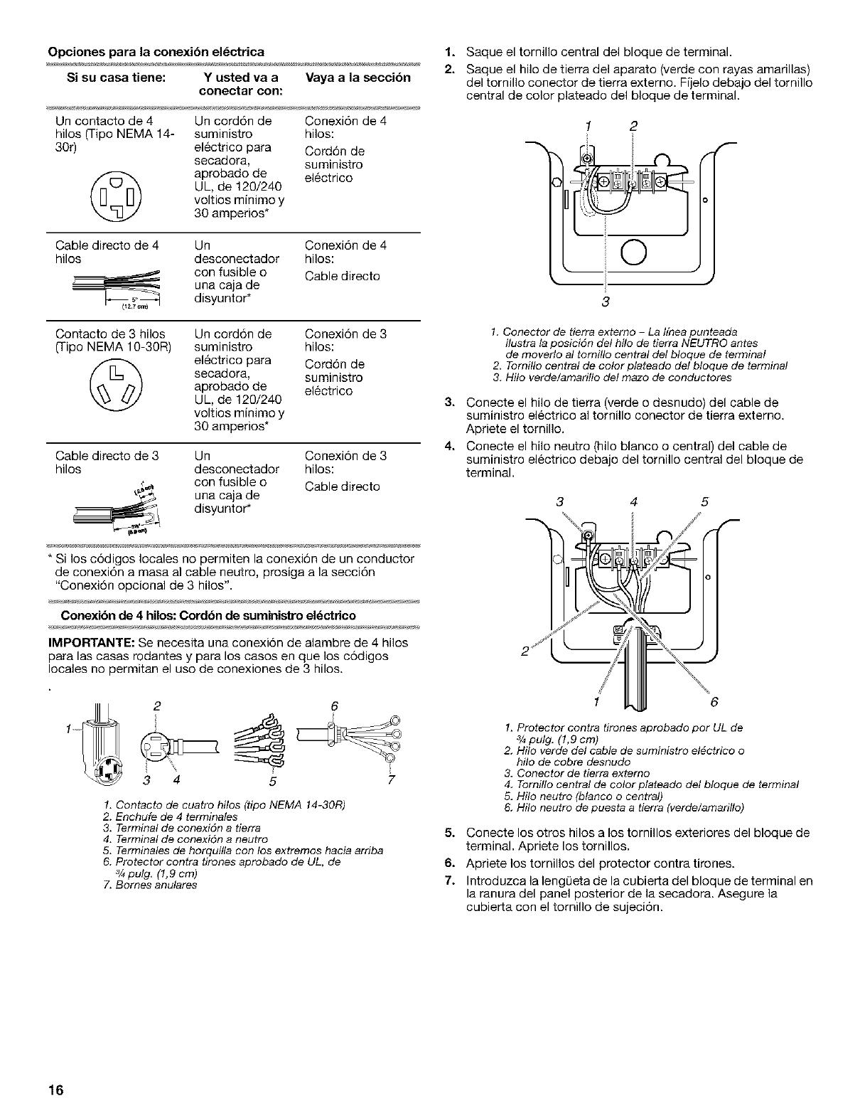
Opciones para la conexibn el_ctrica 1. Saque el tornillo central del bloque de terminal.
__ 2. Saque el hilo de tierra del aparato (verde con rayas amarillas)
Si su casa tiene: Y usted va a Maya a la secci6n del tornillo conector de tierra externo. Fijelo debajo del tornillo
conectar con:
Un contacto de 4 Url cord6n de Conexi6n de 4
hilos (Tipo NEMA 14- suministro hilos:
30r) electrico para Cord6n de
secadora, suministro
aprobado de electrico
UL, de 120/240
voltios mirlimo y
30 amperios*
Cable directo de 4 Un Conexi6n de 4
hilos desconectador hilos:
con fusible o Cable directo
urla caja de
_,_ disyuntor*
central de color plateado del bloque de terminal.
1 2
O
3
Contacto de 3 hilos Url cord6n de Conexi6n de 3
0-ipo NEMA 10-30R) suministro hilos:
(_ electrico para Cord6n de
secadora, suministro
aprobado de electrico
UL, de 120/240
voltios mirlimo y
30 amperios*
Cable directo de 3 Un Conexi6n de 3
hilos desconectador hilos:
con fusible o Cable directo
urla caja de
disyuntor*
* Si los c6digos locales no permiten la conexi6n de un conductor
de conexi6n a masa al cable neutro, prosiga a la secci6n
"Conexi6n opcional de 3 hilos'.
Conexibn de 4 hilos: Cordbn de suministro el6ctrico
IMPORTANTE: Se necesita urla conexi6n de alambre de 4 hilos
para las casas radantes y para los casos en que los c6digos
locales no permitan el uso de conexiones de 3 hilos.
2
3
6
5 7
1. Contacto de cuatro hitos (tipo NEMA 14-30R)
2. Enchufe de 4 terminales
3. Terminal de conexi6n a tierra
4. Terminal de conexidn a neutro
5. Terminales de horquilta con los extremos hacia arriba
6. Protector contra drones aprobado de UL, de
3/4pulg. (1,9 cm)
7. Bornes anulares
1. Conector de tierra externo - La t/nea punteada
itustra la posici6n del hito de tierra NEUTRO antes
de moverto at tomillo central del bloque de terminal
2. Tornillo central de color plateado del btoque de terminal
3 Hilo verde/amarillo del mazo de conductores
3. Conecte el hilo de tierra (verde o desnudo) del cable de
suministro electrico al tornillo conector de tierra externo.
Apriete el tornillo.
4. Conecte el hilo neutro (hilo blanco o central) del cable de
suministro electrico debajo del tornillo central del bloque de
terminal,
3 4
6
1. Protector contra tirones aprobado por UL de
3/4putg. (1,9 cm)
2. Hilo verde det cable de suministro el#ctrico o
hito de cobre desnudo
3. Conector de tierra extemo
4. Tornillo central de color plateado del bloque de terminal
5. Hilo neutro (blanco o central)
6. Hilo neutro de puesta a tierra (verde/amarillo)
5. Conecte los otros hilos a los tornillos exteriores del bloque de
terminal. Apriete los tornillos.
6. Apriete los tornillos del protector contra tirones.
7. Irltroduzca laleng0eta de la cubier[a del bloque de termirlal en
la rarlura del panel posterior de la secadora. Asegure la
cubier[a con el tornillo de sujeci6n.
16

Conexibn de 4 hilos: Cable directo
IMPORTANTE: Se necesita una conexi6n de alambre de cuatro
hilos para las casas rodantes y para los casos en que los c6digos
locales no permitan el uso de conexiones de 3 hilos.
El cable de conexi6n directa debe tener 5 pies (1,52 m) extra de
largo para poder mover la secadora si fuese necesario.
Pele 5 pulg. (12,7 cm) de la cubierta exterior desde el extremo del
cable, dejando el hilo de tierra desnudo a 5 pulg. (12,7 cm). Corte
11/2pulg. (3,8 cm) de los 3 hilos restantes. Pele el aislamiento 1
pulg. (2,5 cm) hacia atras. Doble los extremos de los hilos para
formar un gancho.
3. Conecte el hilo de tierra (verde o desnudo) del cable de
suministro electrico al tornillo del conector de tierra externo.
Apriete el tornillo.
4. Coloque el extremo del hilo neutro en forma de gancho (hilo
blanco o central) del cable de suministro electrico debajo del
tornillo central del bloque de terminal (con el gancho mirando
hacia la derecha). Apriete y junte el extremo enganchado.
Apriete el tornillo.
3 4 5
AI conectar el hilo al bloque de terminal, coloque el extremo del
hilo en forma de gancho debajo del tornillo del bloque de terminal
(con el gancho mirando hacia la derecha). Apriete y junte el
extremo en forma de gancho y apriete el tornillo. Vea el ejemplo a
continuaci6n.
1. Saque el tornillo central del bloque de terminal.
2. Saque el hilo de tierra del aparato (verde con rayas amarillas)
del tornillo conector de tierra externo. Fijelo debajo del tornillo
central de color plateado del bloque de terminal.
1 2
1. Conector de tierra externo - La lfnea punteada
itustra la posicidn del hito de tierra NEUTRO antes
de moverlo al tornillo central del bloque de terminal
2. Tornillo central de color ptateado del bloque de terminal
3. Hilo verde/amarillo del mazo de conductores
1 6
1. Protector contra tirones aprobado por UL de
3/_pulg. (1,9 cm)
2. Hilo verde del cable de suministro electrico o
hflo de cobre desnudo
3. Conector de tierra externo
4. Tornillo central de color plateado del bloque de
terminal
5. Hilo neutro (hilo blanco o central)
6. Hilo neutro de puesta a tierra (verde/amarillo)
5. Coloque los extremos enganchados de los otros hilos del
cable de suministro electrico debajo de los tornillos exteriores
del bloque de terminal (con los ganchos mirando hacia la
derecha). Apriete y junte los extremos enganchados. Apriete
los tornillos.
!! !!
6. Apriete los tornillos del protector contra tirones.
7. Introduzca lalengQeta de la cubier[a del bloque de terminal en
la ranura del panel posterior de la secadora. Asegure la
cubier[a con el tornillo de sujeci6n.
17
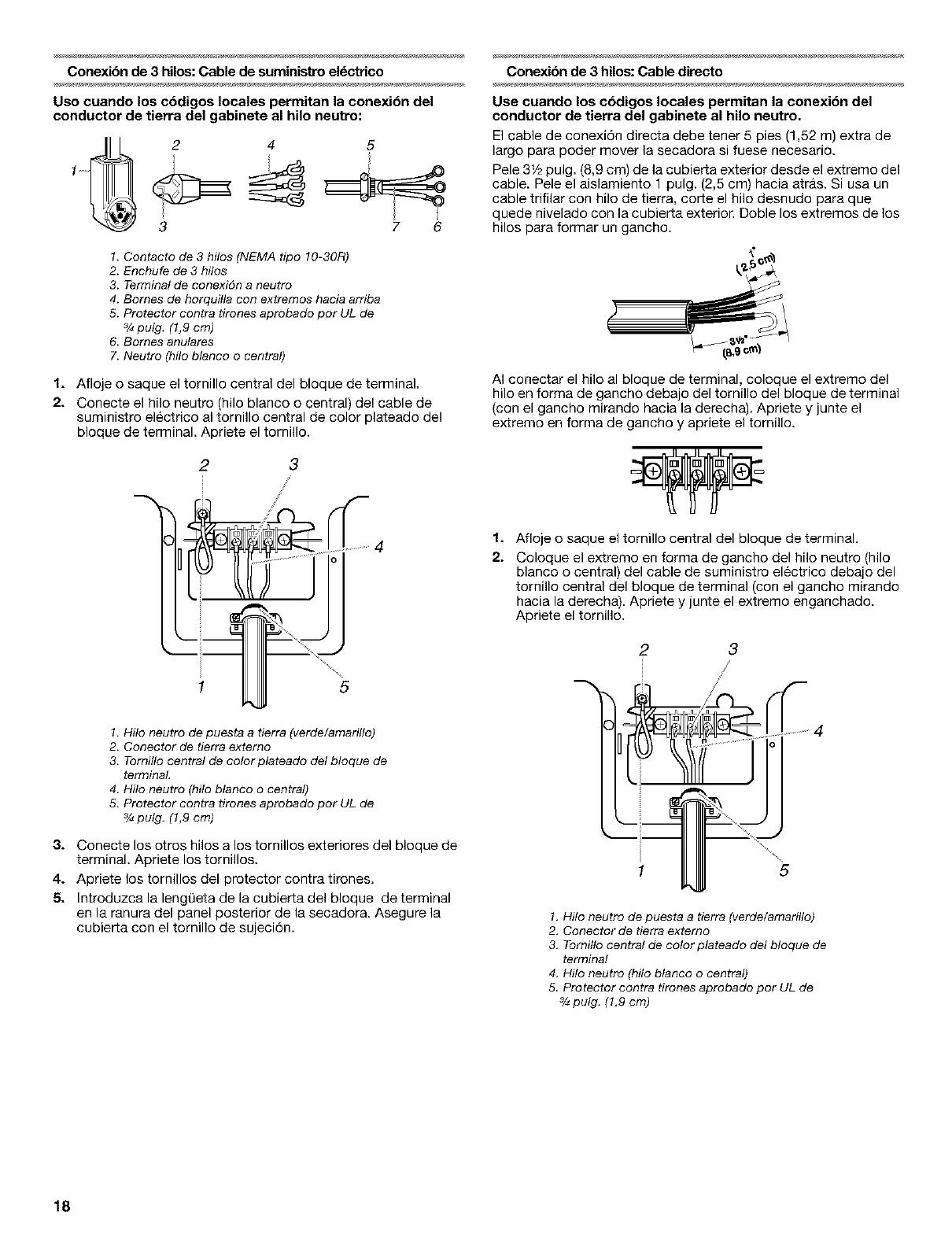
Conexibn de 3 hilos: Cable de suministro el_ctrico
Uso cuando los cbdigos locales permitan la conexibn del
conductor de tierra del gabinete al hilo neutro:
2 4 5
3 7 6
1. Contacto de 3 hitos (NEMA tipo 10-30R)
2. Enchufe de 3 hilos
3. Terminal de conexi6n a neutro
4. Bomes de horquitta con extremos hacia ardba
5. Protector contra tirones aprobado por UL de
3/_pulg. (1,9 cm)
6. Bomes anutares
7. Neutro (hito btanco o central)
1. Aflojeosaqueeltornillocentraldelbloquedeterminal.
2. Conecte el hilo neutro (hilo blanco o central) del cable de
suministro electrice al tornille central de color plateado del
bloque de terminal. Apriete el ternillo.
2 3
/
J
C
1 5
1. Hilo neutro de puesta a tierra (verde/amarillo)
2. Conector de tierra externo
3. Tornillo central de color ptateado det bloque de
terminal,
4. Hilo neutro (hito btanco o central)
5. Protector contra tirones aprobado por UL de
3/_pulg. (1,9 cm)
3. Conecte los otros hilos a los tornillos exteriores del bloque de
terminal. Apriete los tornillos.
4. Apriete los tornillos del protector contra tirones.
5. Introduzca la lengL)eta de la cubierta del bloque de terminal
en la ranura del panel posterior de la secadora. Asegure la
cubierta con el tornillo de sujeci6n.
Conexibn de 3 hUos:Cable directo
Use cuando los c6digos locales permitan la conexi6n del
conductor de tierra del gabinete al hilo neutro.
El cable de conexi6n directa debe tener 5 pies (1,52 m) extra de
largo para poder mover la secadora si fuese necesario.
Pele 31/2pulg. (8,9 cm) de la cubierta exterior desde el extreme del
cable. Pele el aislamiento 1 pulg. (2,5 cm) hacia atr_.s. Si usa un
cable trifilar con hilo de tierra, corte el hilo desnudo para que
quede nivelado con la cubierta exterior. Doble los extremos de los
hilos para formar un gancho.
AI conectar el hilo al bloque de terminal, coloque el extremo del
hilo en forma de 9ancho debajo del torni]lo del bloque de terminal
(con el gancho mirando hacia la derecha). Apriete y junte el
extreme en forma de 9ancho y apriete el tornillo.
1. Afloje o saque el tornillo central del bloque de terminal.
2. Coloque el extreme en forma de gancho del hilo neutro (hilo
blanco o central) del cable de suministro electrico debajo del
tornillo central del bloque de terminal (con el gancho mirando
hacia la derecha). Apriete y junte el extreme enganchado.
Apriete el tornillo.
2 3
\
5
1. Hilo neutro de puesta a tierra (verde/amadtto)
2. Conector de tierra externo
3. Tomitto central de cotor plateado del bloque de
termina!
4. Hilo neutro (hilo blanco o central)
5 Protector contra tirones aprobado por UL de
3/4pulg. (1,9 cm)
18

3. Coloque los extremos enganchados de los otros hilos del
cable de suministro electrico debajo de los tornillos exteriores
del bloque de terminal (con los ganchos mirando hacia la
derecha), Apriete y junte los extremos enganchados, Apriete
los tornillos.
!! !!
4. Apriete los tornillos del protector contra tirones,
5. Introduzca laleng0eta de la cubierta del bloque de terminal en
la ranura del panel posterior de la secadora. Asegure la
cubierta con el tornillo de sujeci6n.
Conexibn opcional de 3 hilos
Use para cable directo o cable de suministro el_ctrico donde
los cbdigos locales no permitan la conexibn del conductor de
tierra del gabinete con el hilo neutro.
1. Saque el tornillo central del bloque de terminal.
2. Saque el hilo de tierra del aparato (verde con rayas amarillas)
del tornillo conector de tierra extemo, Conecte el hilo de tierra
del aparato y el hilo neutro (hilo blanco o central) del cord6n/
cable de suministro electrico debajo del tornillo central de
color plateado del bloque de terminal. Apriete el tornillo.
3. Conecte los otros hilos a los tornillos exteriores del bloque de
terminal, Apriete los tornillos.
!! !!
4. Apriete los tornillos del protector contra tirones.
5. Introduzca laleng0eta de la cubierta del bloque de terminal en
la ranura del panel posterior de la secadora. Asegure la
cubierta con el tornillo de sujeci6n.
6. Conecte un hilo de tierra de cobre separado desde el tornillo
conector de tierra externo a tierra adecuada.
1 2
\
3
1. Conector de tierra externo
2. Hilo neutro de puesta a tierra (verde/amadtto)
3. Hilo neutro (hilo blanco o central)
4. Camino de puesta a tierra determinado por un
electricista capacitado.
Peligro de Incendio
Use un ducto de escape de metal pesado.
No use un ducto de escape de pl_stico.
No use un ducto de escape de aluminio.
No seguir estas instrucciones puede ocasionar
la muerte o incendio.
ADVERTENCIA: Para reducir el riesgo de incendio, esta
secadora DEBE VENTILARSE HAClA EL EXTERIOR.
Se debe usar un ducto de escape de metal pesado de 4 pulg.
(10,2 cm) y abrazaderas, Los productos de ventilaci6n
DURASAFE TM son recomendables,
19

Los productos de ventilaci6n DURASAFF Mpueden comprarse
en su distribuidor o Ilamando a Piezas y Accesorios Whirlpool.
Para obtener m&s informaci6n tome como referencia la secci6n
"Ayuda o servicio tecnico" de sus "lnstrucciones para el usuario
de la secadora".
• No ventile la secadora hacia un ducto de escape de gas,
chimenea, pared, techo o el espacio oculto de un edificio.
• No use una capota de ventilaci6n con pestillo magnetico.
• No instale el ducto de escape de metal flexible en paredes,
techos o pisos encerrados.
• Para asegurar el ducto de escape no use tornillos u otros
dispositivos que se extiendan hacia el interior de dicho
conducto.
IMPORTANTE: Observe todas las normas y ordenanzas vigentes.
La ventilacibn inadecuada puede ocasionar la
acumulaci6n de humedad y pelusa en la casa, Io cual
puede dar come resultado:
• DaSos de humedad en la carpinteria, muebles, pintura,
empapelado, alfombras, etc.
• Problemas en la limpieza de la casa y de salud.
Use un ducto de escape de metal pesado. No use un ducto de
escape de plastico o de hoja de aluminio.
Se recomienda el ducto de escape de metal pesado para evitar
que se aplaste o se tuerza.
El ducto de escape de metal flexible debe extenderse y
sostenerse por completo cuando la secadora este en su
ubicaciSn final. Quite el exceso del conducto de metal flexible
para evitar que se doble y se tuerza, Io cual podria dar lugar a una
reducci6n del flujo de aire y un funcionamiento insuficiente.
Una capota de ventilaci6n debe tapar el ducto de escape para
evitar el ingreso de roedores e insectos a la casa.
La capota de ventilaci6n debe estar por Io menos a 12 pulg.
(30,5 cm) de distancia del piso o de cualquier objeto que pudiese
estar en el trayecto del ducto de escape (como flores, rocas o
arbustos, etc).
Si se usa un sistema de ventilaci6n existente, limpie la pelusa que
est,. en toda la Iongitud del sistema y aseg[3rese de que la capota
de ventilaci6n no este obstruida con pelusa. Reemplace cualquier
ducto de escape de plastico o de hoja de metal por uno de metal
rigido o de metal flexible.
Utilice abrazaderas para sellar todas las juntas. No use cinta
adhesiva para conductos, tornillos ni otros dispositivos de fijaci6n
que se extiendan dentro del conducto de salida de aire, para fijar
el conducto.
Instalaciones tipicas de escape
Las instalaciones tipicas tienen la ventilaci6n en la parte posterior
de la secadora.
1--
/q
2
k 3
117-5
2
1. Secadora
2. Codo
3. Pared
4. Capota de ventflacidn
5. Abrazaderas
6. Tubo de metal rfgido o tubo de
metal flexible
7. Longitud necesaria del ducto de
escape para conectar los codos
8. Satida de ventflacidn
Instalacibn est&ndar de ventUacibn con ductos de metal
rigidos o ductos de metal flexibles
Instalaciones alternas pare espacios limitados
Los sistemas de ventilaci6n vienen en una amplia gama.
Seleccione el tipo m&s apropiado para su instalaci6n. A
continuaci6n se ilustran dos tipos de instalaci6n para espacios
limitados. Consulte las instrucciones del fabricante.
1 2
1. tnstalaci6n en la parte superior (tambien est_
disponibte con un codo de desviacidn)
2. tnstalaci6n de periscopio
20
/