Page is loading ...

Please file in Service Binder
5693 982 - 04 02/2015
VITOTRONIC
r
300
Vitotronic 300
Type GW2B
Weather-compensated, digital boiler control units
For use with Boiler models VD2A, VD2 and CT3
for use by heating contractor
Installation and Service
Instructions
Read and save these instructions
for future reference.
Product may not be exactly as shown
IMPORTANT
Certified as a component
part for Viessmann boilers

Vitotronic 300, GW2B Installation and Service
2
5693 982 - 04
General
Safety, Installation and Warranty Requirements
Please ensure that these instructions are read and understood before commencing installation. Failure to comply with
the instructions listed below and details printed in this manual can cause product/property damage, severe personal
injury, and/or loss of life. Ensure all requirements below are understood and fulfilled (including detailed information
found in manual subsections).
WARNING
Installers must follow local regulations with respect to
installation of carbon monoxide detectors. Follow the
Viessmann maintenance schedule of the boiler contained
in this manual.
Product documentation
Read all applicable documentation before commencing
installation. Store documentation near boiler in a
readily accessible location for reference in the future
by service personnel.
For a listing of applicable literature,
please see section entitled “Important
Regulatory and Safety Requirements”.
Warranty
Information contained in this and
related product documentation must
be read and followed. Failure to do
so renders the warranty null and void.
Licensed professional heating contractor
The installation, adjustment, service and maintenance
of this equipment must be performed by a licensed
professional heating contractor.
Please see section entitled
“Important Regulatory and Installation
Requirements”.
Advice to owner
Once the installation work is complete, the heating
contractor must familiarize the system operator/
ultimate owner with all equipment, as well as safety
precautions/requirements, shutdown procedure, and
the need for professional service annually before the
heating season begins.
Operating and Service Documentation
It is recommended that all product documentation such as
parts lists, operating and service instructions be handed
over to the system user for storage. Documentation is to
be stored near boiler in a readily accessible location for
reference by service personnel.
Product Information
This document describes Vitotronic 300 type GW2B
when used:
in a single boiler system
for Vitorond 200 VD2 / VD2A Series boiler:
Order Number 7533386
Serial No. 7514781 jjjjjjjjj
for Vitocrossal 300 CT3Series boiler:
Order Number 7534260
Serial No. 7514781 jjjjjjjjj

3
5693 982 - 04
Vitotronic 300, GW2B Installation and Service
General
Preparing for Installation
Control Unit Installation
Installation Sequence
Safety, Installation and Warranty Requirements..............2
Product Information....................................................2
Designations In The System Examples.........................6
System Example 1......................................................7
Single boiler system with Therm-Control...................7
Equipment required................................................8
Electrical installation scheme................................10
Mixing valve extension PCB..................................12
Required code....................................................12
System Example 2....................................................13
Single boiler system with shunt pump....................13
Equipment Required..............................................14
Electrical installation scheme................................16
Mixing valve extension PCB..................................18
Required code....................................................18
System Example 3....................................................19
Single boiler system with shunt pump and
3-way mixing valve..............................................19
Equipment required..............................................20
Electrical installation scheme.................................22
Mixing valve extension PCB..................................24
Required code.....................................................24
System Example 4....................................................25
Single boiler system with Vitocrossal.....................25
Equipment required..............................................26
Electrical installation scheme................................28
Mixing valve extension PCB..................................30
Required code.....................................................30
System Extension.....................................................30
Mounting the Control Unit..........................................31
Fitting the Control Unit Front......................................32
Opening the Control Unit...........................................33
Overview of Electrical Connections.............................34
Pump Connection Overview.......................................36
Inserting Cables and Applying Strain Relief...................37
Inserting the Boiler Coding Card.................................37
Inserting the LON Communication Module....................38
Adjusting the Fixed High Limit (if required)...................38
Changing the Adjustable High Limit (if required)...........39
Connecting Sensors...................................................39
Power Supply...........................................................40
External Connections.................................................41
Connecting Actuators................................................42
Connecting the Central Fault Message Facility..............43
Connection of Low Water Cut-off Device 150 ..............43
Connecting to Safety Equipment 150 ..........................43
External Burner Blocking 150 .....................................44
Page
Table of Contents

Table of Contents
4
Page
5693 982 - 04
Vitotronic 300, GW2B Installation and Service
Installation Sequence
Commissioning
Service Scans
Troubleshooting
Function and Description
Code 1
Code 2
Connections to Terminal aBA.....................................44
Vitotronic 100, GC 1 with 30% LTP Package (VD2 only)..45
External Demand via Switching Contact.......................46
External Demand via 0 - 10V Input..............................46
External Blocking via Switching Contact........................47
External “Mixing Valve Closed”/“Mixing Valve Open”.......48
External Changeover of Multi Stage/
Modulating Burners...................................................48
External Heating Program Changeover.........................49
Connecting of Combustion Air Device.........................50
Burner Connection, Burner Control Wiring....................51
Burner Connection, Motor Power Supply......................53
Changing the Language.............................................56
Setting the Date and Time.........................................56
Testing the High Limits Safety Cut-out........................56
Matching the Coding Addresses
to the System Version................................................57
Checking Actuator and Sensors..................................58
Adjusting Heating Curves...........................................60
Connecting the Control Unit to the LON.......................62
Making the LON Connection.......................................64
Calling up the Service Menu.......................................65
Exit Service Menu.....................................................65
Scanning Operating Data...........................................66
Brief Scan...............................................................66
Scanning and Resetting Service Display.......................68
Fault Display............................................................68
Boiler Water Temperature Control ..............................77
Heating Circuit Control..............................................81
DHW Tank Temperature Control ...............................85
Calling Up Coding Level 1..........................................88
“General” Group.......................................................89
“Boiler” Group..........................................................91
“DHW” Group...........................................................91
“Solar” Group...........................................................92
”Heating Circuit 1”, “Heating Circuit 2”,
“Heating Circuit 3” Group..........................................93
Calling Up Coding Level 2..........................................97
“General” Group.......................................................98
“Boiler” Group........................................................106
“DHW” Group........................................................109
“Solar” Group........................................................111
”Heating Circuit 1”, “Heating Circuit 2”,
“Heating Circuit 3” Group........................................115

5
Page
5693 982 - 04
Vitotronic 300, GW2B Installation and Service Table of Contents
Connection and Wiring Diagram, Type GW2B.............120
Sensors.................................................................124
Outside Temperature Sensor...............................125
Flue Gas Temperature Sensor..............................125
Extension Kit, Mixing Valve......................................126
Extension EA1 Accessory (optional)..........................127
Type GW2B..........................................................128
Specifications........................................................129
Designs
Components
Parts Lists
Specification

Vitotronic 300, GW2B Installation and Service
5693 982 - 04
6
Preparing for Installation
Designations in the System Examples
In the following system examples, the Vitotronic 300,
type GW2B, is used as the control unit.

7
5693 982 - 04
Vitotronic 300, GW2B Installation and Service
System Example 1
Preparing for Installation
Single boiler system: Boiler with Therm-Control
Hydraulic installation scheme
Note: This scheme is a basic example without
shut-off devices or safety equipment.
This does not replace the need for professional
planning on site.

Vitotronic 300, GW2B Installation and Service
5693 982 - 04
8
Preparing for Installation
System Example 1 (continued)
Equipment required
Pos. Description
1Boiler
2Vitotronic 300 GW2B
3Outside temperature sensor ATS
4Boiler water temperature sensor KTS
5Therm-Control temperature sensor
rR ON/OFF switch (on site)
6DHW tank
7DHW tank temperature sensor STS
8DHW pump UPSB
9DHW recirculation pump ZP
qP Heating circuit 2
qW Heating circuit pump M2
Mixing valve extension kit:
qQ Supply temperature sensor M2 as contact temperature sensor
and
qE Mixing valve motor M2
or
Supply temperature sensor M2 as
qQ - Contact temperature sensor
or
- Immersion temperature sensor
and
qE Mixing valve motor for flanged mixing valve M2
qR Heating circuit 3
qZ Heating circuit pump M3
Mixing valve extension kit:
qT Supply temperature sensor M3 as contact temperature sensor
and
qU Mixing valve motor M3
or
Supply temperature sensor M3 as
qT - Contact temperature sensor
or
- Immersion temperature sensor
and
qU Mixing valve motor for flanged mixing valve M3

9
5693 982 - 04
Vitotronic 300, GW2B Installation and Service
Equipment required
Pos. Description
Accessories
qI Connection to safety equipment aBÖ (see page 43)
qO Minimum pressure switch or limiter SDB
wP Maximum pressure limiter SDB
wQ Water level limiter (low water cut-off) WB
wW Central fault message system S
wE Flue gas temperature sensor AGS
wR Vitotrol 200A or Vitotrol 300A
wZ Contactor relay
wU Downstream heating circuit controller, switching contact closed:
Signal for mixing valve “Close”
eP Extension EA1
eQ 1 analog input (0 – 10V)
- Specification of the set boiler water temperature
eW 3 digital inputs
- External heating program changeover, separately adjustable for heating circuits 1 to 3
- External demand
- External blocking with fault message input
- Fault message input
- Short term operation of DHW recirculation pump
eE 1 switching output (floating changeover contact)
- Switching a feed pump to a substation
- Signalling reduced mode for a heating circuit
External hook-ups
eR - External demand
eT - External changeover of stepped/modulating burners
eZ - External blocking/mixing valve closed
eU - External changeover of heating program/external mixing valve open
eO Vitocom 100
rP KM BUS distributor, for several KM BUS participants
rQ LON communication module for communication with the following components:
Vitotronic 200-H
Preparing for Installation
System Example 1 (continued)

Vitotronic 300, GW2B Installation and Service
5693 982 - 04
10
Preparing for Installation
System Example 1 (continued)
Electrical installation scheme
Main PCB 120V

11
5693 982 - 04
Vitotronic 300, GW2B Installation and Service Preparing for Installation
System Example 1 (continued)
Main PCB LV connections

Vitotronic 300, GW2B Installation and Service
5693 982 - 04
12
Preparing for Installation
System Example 1 (continued)
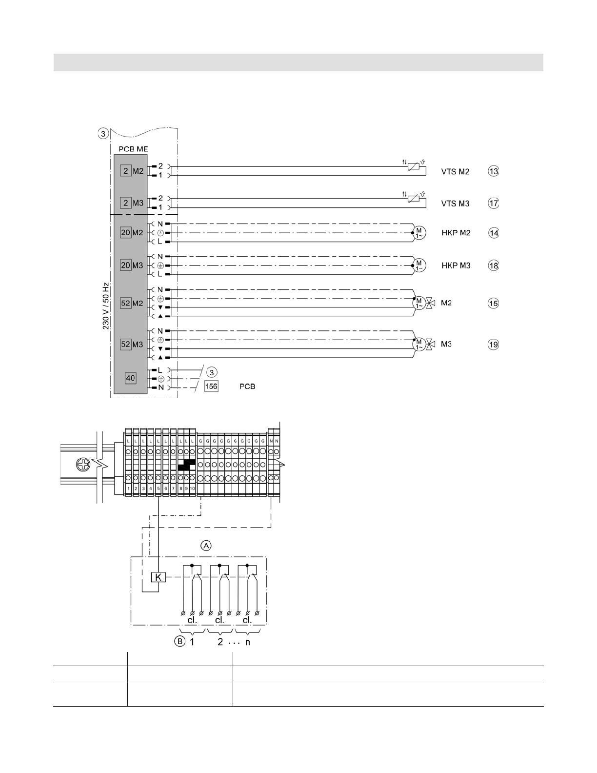
Mixing valve extension PCB
Wiring diagram
Closing mixing valves installed downstream via
temperature sensor T1 in heating systems with heating
circuit control units that are not connected to the boiler
control unit via LON.
Required code
4C:2 “General” group Use of plug sÖ A1 to close the downstream mixing valves.
0d:1 “Boiler” group Temperature sensor Therm-Control affects the mixing valves of
downstream heating circuits (factory set condition).

13
5693 982 - 04
Vitotronic 300, GW2B Installation and Service Preparing for Installation
System Example 2
Single boiler system: Boiler with shunt pump for return
temperature raising
Hydraulic installation scheme
Note: This scheme is a basic example without
shut-off devices or safety equipment.
This does not replace the need for professional
planning on site.

Vitotronic 300, GW2B Installation and Service
5693 982 - 04
14
Preparing for Installation
System Example 2 (continued)
Equipment required
Pos. Description
1Boiler
2Boiler water temperature sensor KTS
3Vitotronic 300 GW2B
4Outside temperature sensor ATS
5Shunt pump BP
6Temperature sensor T2
- Contact temperature sensor
or
- Immersion temperature sensor
7Temperature sensor T1
- Contact temperature sensor
or
- Immersion temperature sensor
rR ON/OFF switch (on site)
8DHW tank
9DHW tank temperature sensor STS
qP DHW pump UPSB
qQ DHW recirculation pump ZP
qW Heating circuit 2
qR Heating circuit pump M2
Mixing valve extension kit:
qE Mixing valve motor for flanged mixing valve M2
qR Heating circuit 3
qT Mixing valve motor M2
or
Supply temperature sensor M2 as
qE - Contact temperature sensor
or
- Immersion temperature sensor
and
qT Mixing valve motor for flanged mixing valve M2
qZ Heating circuit 3
qI Heating circuit pump M3
Mixing valve extension kit:
qU Supply temperature sensor M3 as contact temperature sensor
and
qO Mixing valve motor M3
or
Supply temperature sensor M3 as contact temperature sensor

15
5693 982 - 04
Vitotronic 300, GW2B Installation and Service Preparing for Installation
System Example 2 (continued)
Equipment required
Pos. Description
qU - Contact temperature sensor
or
- Immersion temperature sensor
and
qO Mixing valve motor for flanged mixing valve M3
Accessories
wP Connection to safety equipment aBÖ (see page 43)
wQ Minimum pressure switch or limiter SDB
wW Maximum pressure limiter SDB
wE Water level limiter (low water cut-off) WB
wR Central fault message system S
wT Flue gas temperature sensor AGS
wZ Vitotrol 200A or Vitotrol 300A
wI Contactor relay
wO Downstream heating circuit controller, switching contact closed:
Signal for mixing valve “Close”
eP Extension EA1
eQ 1 analog input (0 – 10V)
- Specification of the set boiler water temperature
eW 3 digital inputs
- External heating program changeover, separately adjustable for heating circuits 1 to 3
- External demand
- External blocking with fault message input
- Fault message input
- Short term operation of DHW recirculation pump
eE 1 switching output (floating changeover contact)
- Switching a feed pump to a substation
- Signalling reduced mode for a heating circuit
External hook-ups
eR - External demand
eT - External changeover of stepped/modulating burners
eZ - External blocking/mixing valve closed
eU - External changeover of heating program/external mixing valve open
eO Vitocom 100
rP KM BUS distributor, for several KM BUS participants
rQ LON communication module for communication with the following components:
Vitotronic 200-H

Vitotronic 300, GW2B Installation and Service
5693 982 - 04
16
Preparing for Installation
System Example 2 (continued)
Electrical installation scheme
Main PCB 120V

17
5693 982 - 04
Vitotronic 300, GW2B Installation and Service Preparing for Installation
System Example 2 (continued)
Main PCB LV connections
Vitotronic 300, GW2B Installation and Service
5693 982 - 04
18
Preparing for Installation
System Example 2 (continued)
Mixing valve extension PCB
Required code
4C:2 “General” group Use of plug sÖ A1 to close the downstream mixing valves.
0d:1 “Boiler” group Temperature sensor T1/Therm-Control affects the mixing valves of
downstream heating circuits (factory set condition).
Wiring diagram
Closing mixing valves installed downstream via
temperature sensor T1 in heating systems with heating
circuit control units that are not connected to the boiler
control unit via LON.
Low voltage
Main

19
5693 982 - 04
Vitotronic 300, GW2B Installation and Service Preparing for Installation
System Example 3
Single boiler system: Boiler with shunt pump and 3-way
mixing valve for return temperature control
Hydraulic installation scheme
Note: This scheme is a basic example without
shut-off devices or safety equipment.
This does not replace the need for professional
planning on site.

Vitotronic 300, GW2B Installation and Service
5693 982 - 04
20
Preparing for Installation
System Example 3 (continued)
Equipment required
Pos. Description
1Boiler
2Boiler water temperature sensor KTS
3Vitotronic 300 GW2B
4Outside temperature sensor ATS
5Shunt pump BP
63-way mixing valve
7Temperature sensor T2
- Contact temperature sensor
or
- Immersion temperature sensor
8Temperature sensor T1
- Contact temperature sensor
or
- Immersion temperature sensor
rR ON/OFF switch (on site)
9DHW tank
qP DHW tank temperature sensor STS
qQ DHW pump UPSB
qW DHW recirculation pump ZP
qE Heating circuit 2
qT Heating circuit pump M2
Mixing valve extension kit:
qR Supply temperature sensor M2 as contact temperature sensor
and
qZ Mixing valve motor for flanged mixing valve M2
qU Heating circuit 3
qO Heating circuit pump M3
Mixing valve extension kit:
qI Supply temperature sensor M3 as contact temperature sensor
and
wP Mixing valve motor M3
or
Supply temperature sensor M3 as contact temperature sensor
/