Page is loading ...

TRENDnet User’s Guide
Cover Page

© Copyright 2023 TRENDnet. All Rights Reserved.
TRENDnet User’s Guide
Table of Contents
i
Contents
Product Overview ........................................................................... 1
Package Contents .......................................................................................................... 1
Features ......................................................................................................................... 1
Key Features .................................................................................................................. 3
Application Diagram ...................................................................................................... 4
Switch Installation .......................................................................... 5
Desktop Hardware Installation ...................................................................................... 5
Rack Mount Hardware Installation ................................................................................ 5
Basic Installation ............................................................................................................ 6
Connectivity Example .................................................................................................... 8
Configure your switch (Web-based UI) ............................................ 9
Access your switch management page .......................................................................... 9
System Info .................................................................................................................... 9
View your switch status information ................................................................... 9
Real-Time Statistics ...................................................................................................... 12
View SFP/SFP+ Status .................................................................................................. 12
System .......................................................................................... 13
Set your system information ............................................................................. 13
Set your IPv4 settings ........................................................................................ 13
Set your IPv6 settings ........................................................................................ 15
Create additional IPv4 address interfaces ......................................................... 16
Create additional IPv6 address interfaces ......................................................... 17
Configure ARP settings ...................................................................................... 18
SNMP ........................................................................................................................... 23
Global Settings ................................................................................................... 23
User List ............................................................................................................. 23
Community List .................................................................................................. 23
Group List ........................................................................................................... 24
Access List .......................................................................................................... 24
View List ............................................................................................................. 25
RMON .......................................................................................................................... 25
Statistics ............................................................................................................. 25
Event List ........................................................................................................... 26
Event Log Table .................................................................................................. 26
Alarm List ........................................................................................................... 27
History ............................................................................................................... 28
History Log Table ............................................................................................... 29
MAC Address Table...................................................................................................... 29
Static MAC Address ........................................................................................... 29
Dynamic MAC Address ...................................................................................... 29
MAC Aging Time ................................................................................................ 30
SFP Module Information .............................................................................................. 30
Module & DDM .................................................................................................. 30
Network ....................................................................................... 31
Physical Interface......................................................................................................... 31
Configure Physical Interfaces ............................................................................ 31
Port Isolation ..................................................................................................... 32
Mirroring............................................................................................................ 32
Jumbo Frames .................................................................................................... 33
VLAN Settings .............................................................................................................. 34
802.1Q VLAN ...................................................................................................... 34
PVID & Ingress Filter .......................................................................................... 35
GVRP ............................................................................................................................ 36
Protocol ............................................................................................................. 36
Port Settings ...................................................................................................... 36
Spanning Tree .............................................................................................................. 37
Protocol ............................................................................................................. 37
Root Bridge Information .................................................................................... 38
RSTP Port Settings ............................................................................................. 38
CIST Port Settings ............................................................................................... 39

© Copyright 2023 TRENDnet. All Rights Reserved.
TRENDnet User’s Guide
Table of Contents
ii
MST .................................................................................................................... 40
MST Port Settings .............................................................................................. 41
Trunk ............................................................................................................................ 42
Settings .............................................................................................................. 42
LACP ................................................................................................................... 42
LACP Timeout ..................................................................................................... 43
IGMP Snooping ............................................................................................................ 43
Global Settings ................................................................................................... 43
Fast Leave .......................................................................................................... 43
VLAN Settings..................................................................................................... 44
Querier Settings ................................................................................................. 44
Router Settings .................................................................................................. 45
MLD Snooping .............................................................................................................. 45
Global Settings ................................................................................................... 45
Fast Leave .......................................................................................................... 45
VLAN Settings..................................................................................................... 46
Querier Settings ................................................................................................. 46
Router Settings .................................................................................................. 46
Loopback Detection ..................................................................................................... 47
Global Settings ................................................................................................... 47
Voice VLAN .................................................................................................................. 47
Global Settings ................................................................................................... 48
OUI Settings ....................................................................................................... 49
Port Settings ...................................................................................................... 49
LLDP ............................................................................................................................. 50
Enable and configure LLDP ................................................................................ 50
Settings .............................................................................................................. 50
Multicast Filtering ........................................................................................................ 51
Enable Multicast Filtering .................................................................................. 51
Administration ............................................................................................................. 51
Changing login credentials ................................................................................. 51
Logs .............................................................................................................................. 52
Settings .............................................................................................................. 52
Remote Logging ................................................................................................. 52
Log Table ............................................................................................................ 52
QoS (Quality of Service) ................................................................ 53
Global Settings ............................................................................................................. 53
Set QoS settings ................................................................................................. 53
CoS ............................................................................................................................... 53
Set CoS priority settings ..................................................................................... 53
DSCP Mapping ............................................................................................................. 54
Set DSCP (Differentiated Services Code Point) Class Mapping settings ............ 54
Port CoS ....................................................................................................................... 55
Set Port Priority ................................................................................................. 55
Bandwidth Control ...................................................................................................... 55
Bandwidth Control ............................................................................................. 55
Storm Control .................................................................................................... 56
Security ........................................................................................ 56
802.1X Authentication ................................................................................................. 56
Set 802.1X .......................................................................................................... 56
Timeout ............................................................................................................. 56
CLI Timeout ........................................................................................................ 57
Port Security ...................................................................................................... 57
Access Control: Creating MAC ACL .................................................................... 57
Access Control: Configuring MAC ACL ............................................................... 58
Access Control: Creating IPv4 ACL ..................................................................... 58
Access Control: Configuring IPv4 ACL ................................................................ 59
Access Control: Creating IPv6 ACL ..................................................................... 59
Access Control: Configuring IPv6 ACL ................................................................ 60
Port Binding ....................................................................................................... 60
Dial-in User .................................................................................................................. 60
Create Dial-In Users (Local Authentication Method) ......................................... 60
RADIUS ......................................................................................................................... 61

© Copyright 2023 TRENDnet. All Rights Reserved.
TRENDnet User’s Guide
Table of Contents
iii
Add Radius Servers (RADIUS Authentication Method) ...................................... 61
TACACS+ ...................................................................................................................... 62
Add TACACS+ Servers (TACACS+ Authentication Method) ................................ 62
DHCP Snooping ............................................................................................................ 63
Settings .............................................................................................................. 63
VLAN .................................................................................................................. 63
Trusted Port Interfaces ...................................................................................... 64
Denial of Service .......................................................................................................... 65
Denial of Service (DoS) ....................................................................................... 65
Tools ............................................................................................. 66
Firmware Upgrade ....................................................................................................... 66
Upgrade your switch’s firmware ....................................................................... 66
Firmware Upgrade via HTTP Settings ................................................................ 66
Firmware Upgrade via TFTP Settings ................................................................. 67
Dual Image ......................................................................................................... 67
Config Backup Restore ................................................................................................. 68
Config Backup/Restore ...................................................................................... 68
Backup/Restore via HTTP Settings ..................................................................... 68
Backup/Restore via TFTP Settings ..................................................................... 68
Diagnostics ................................................................................................................... 69
Cable Diagnostics Test ....................................................................................... 69
Ping Test ...................................................................................................................... 70
Network Connectivity Test (Ping Tool) .............................................................. 70
IPv6 Ping Test ............................................................................................................... 71
Network Connectivity Test (Ping Tool) .............................................................. 71
Trace Route ................................................................................................................. 71
Reboot ......................................................................................................................... 71
Reboot/Reset to factory defaults ...................................................................... 71
Command Line Interface Reference ............................................... 73
Access your switch command line interface ............................................................... 73
Technical Specifications .............................................................. 162
Troubleshooting ......................................................................... 165
Appendix .................................................................................... 166

© Copyright 2023 TRENDnet. All Rights Reserved.
TRENDnet User’s Guide
TL2-F7120
1
Product Overview
TL2-F7120
Package Contents
In addition to your switch, the package includes:
• Quick Installation Guide
• Power cord
• RJ-45 to RS-232 console cable (1.5m / 5 ft.)
• Rackmount kit
If any package contents are missing or damaged, please contact the retail store, online
retailer, or reseller/distributor from which the product was purchased.
Features
TRENDnet’s 12-Port 10G Layer 2 Managed SFP+ Switch, model TL2-F7120, offers
advanced traffic management controls to meet the evolving demands of SMB networks.
This rack-mountable IPv6-ready managed switch comes with an intuitive web-based
interface. Advanced management features on this ultra-fast 10G SFP+ switch include
LACP to increase bandwidth between switches by grouping ports together, VLANs for
segmenting and isolating virtual LAN groups, QoS for traffic prioritization, port
bandwidth controls, and SNMP monitoring, making this a powerful solution for any SMB
network. Improve voice performance by isolating and prioritizing VoIP traffic from
normal data traffic with an easy-to-use voice VLAN feature.
Free up router resources by offloading routing processes to this 10G managed SFP+
switch by using the L2+ IPv4/IPv6 static routing feature to efficiently route traffic at the
switch level. Take advantage of the available multicast and IGMP/MLD snooping
features to optimize IP surveillance system performance, and minimize network traffic.
TRENDnet’s 10G SFP+ switch features 12 x 10GSFP+ slots for high-speed network uplinks
or downlink NAS/access server connections, providing a cost-effective solution in adding
10G link capability to an SMB network.
Hardware Design
The 10Gb fiber switch provides 12 x 10G SFP+ slots, a built-in power supply, and 1U
rackmount brackets
Switching Capacity
Supports a 240Gbps switch capacity
Smart Fan
The smart fan on the 10G SFP+ switch saves energy and eliminates distracting operating
noise by auto adjusting the fan speed and use based on cooling needs
LED Indicators
LED indicators on the 10G SFP+ switch convey port status

© Copyright 2023 TRENDnet. All Rights Reserved.
TRENDnet User’s Guide
TL2-F7120
2
Jumbo Frame
Sends larger packets, or Jumbo Frames (up to 9KB) for increased performance
Rackmount Design
Save rack space by mounting 2 x TL2-F7120 into 1U space with the optional ETH-F71
dual mount bracket (sold separately)
IPv6 Ready
This 10G SFP+ switch supports Ipv6 configuration and Ipv6 neighbor discovery
IP Routing
Supports inter-VLAN routing and Ipv4/Ipv6 static routing
Traffic Management
A broad range of network configurations are supported by this 10G managed SFP+
switch: 802.1ax link aggregation, , 802.1Q VLAN, Voice VLAN, RSTP, MSTP, Loopback
Detection, GVRP, 802.1p Class of Service (CoS), port bandwidth management, and QoS
queue scheduling
Troubleshooting
A convenient cable diagnostic test and traffic statistics aid in network troubleshooting
Access Control
Features such as IPv4/IPv6 ACL, port security (mac entry restriction), 802.1X, TACACS+,
and RADIUS are compatible with layered access controls
Monitoring
RMON, SNMP, SNMP Trap, and Port Mirroring, and DDM are supported on the 10G SFP+
switch
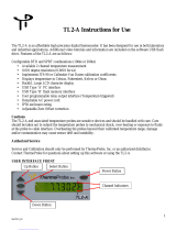
Product Hardware Features
• AC Power Connector – Connect the AC power cord to the connector and
the other side into a power outlet. (Input: 100~240VAC, 50/60Hz)
• Reset Button – Press and hold this button for 15 seconds and release to
reset the switch to factory defaults.
• 10G SFP+ Slots (1-12) – Supports 1000BASE-X (Gigabit Ethernet over
fiber) or 10GBASE-X (10 Gigabit Ethernet over fiber SFP/mini-GBIC
modules for connectivity.
• Console port – Use the included RJ-45 to RS-232 serial console cable to
access the out-of-band command line interface management.

© Copyright 2023 TRENDnet. All Rights Reserved.
TRENDnet User’s Guide
TL2-F7120
3
• Diagnostic LED Indicators
Power LED
On (Green)
:
The device is receiving power and operating normally.
Blinking
(Green)
The device is booting and performing a system self-test.
Off
:
The device is not receiving power and turned off.
Fault LED
On
(Orange)
:
Indicates that there is a hardware issue with the device.
Off
:
Indicates no hardware issues detected and the device
hardware is operating normally.
• 10G SFP+ Slots 1-12 Speed / Link & Activity
On (Green)
:
The link speed is established at 10Gbps (10,000Mbps)
(Left side LED per slot)
On
(Orange)
:
The link speed is established at 1Gbps (1000Mbps).
(Left side LED per slot)
Blinking
:
The SFP/SFP+ slot is transmitting or receiving data.
(Right side LED per slot)
Off
The SFP/SFP+ link is disconnected or not established.
Key Features

© Copyright 2023 TRENDnet. All Rights Reserved.
TRENDnet User’s Guide
TL2-F7120
4
Application Diagram

© Copyright 2023 TRENDnet. All Rights Reserved.
TRENDnet User’s Guide
TL2-F7120
5
Switch Installation
Desktop Hardware Installation
Note: The device images displayed below may be different from your switch model.
The site where you install the hub stack may greatly affect its performance. When
installing, consider the following pointers:
• Install the Switch in a fairly cool and dry place.
• Install the Switch in a site free from strong electromagnetic field generators (such
as motors), vibration, dust, and direct exposure to sunlight.
• Leave at least 10cm of space at the front and rear of the hub for ventilation.
• Install the Switch on a sturdy, level surface that can support its weight, or in an
EIA standard-size equipment rack. For information on rack installation, see the
next section, Rack Mounting.
• When installing the Switch on a level surface, attach the rubber feet to the
bottom of each device. The rubber feet cushion the hub and protect the hub
case from scratching.
Rack Mount Hardware Installation
The switch can be mounted in an EIA standard-size, 19-inch rack, which can be placed in
a wiring closet with other equipment. Attach the mounting brackets at the switch’s
front panel (one on each side), and secure them with the provided screws.
Then, use screws provided with the equipment rack to mount each switch in the rack.

© Copyright 2023 TRENDnet. All Rights Reserved.
TRENDnet User’s Guide
TL2-F7120
6
Basic Installation
3. Assign a static IP address to your computer’s network adapter in the subnet of
192.168.10.x (e.g. 192.168.10.25) and a subnet mask of 255.255.255.0.
4. Open your web browser, and type the IP address of the switch in the address bar, and
then press Enter. The default IP address is 192.168.10.200.
5. Enter the User Name and Password, and then click Login. By default:
User Name: admin
Password: admin
Note: User name and password are case sensitive.
6. You will be prompted to change the default admin password. Enter the admin
password in the fields provided and click Login.
Note: You will need to login to the switch management with updated password moving
forward.

© Copyright 2023 TRENDnet. All Rights Reserved.
TRENDnet User’s Guide
TL2-F7120
7
7. Click System, click System Settings, and then click IP Settings.
8. Configure the switch IP address settings to be within your network subnet, then click
Apply.
Note: You may need to modify the static IP address settings of your computer’s network
adapter to IP address settings within your subnet in order to regain access to the switch.
9. To save configuration setting, click Apply at the top right of the page.
Note: You can also click Reset to discard your changes and revert back to the previous
configurations ettings.

© Copyright 2016 TRENDnet. All Rights Reserved.
8
TRENDnet User’s Guide
TL2-F7120
Connectivity Example

© Copyright 2023 TRENDnet. All Rights Reserved.
TRENDnet User’s Guide
TL2-F7120
9
Configure your switch (Web-based UI)
Access your switch management page
Note: Your switch default management IP address http://192.168.10.200 is accessed
through the use of your Internet web browser (e.g. Microsoft Edge®, Firefox®, Chrome™,
Safari®, and Opera™) and will be referenced frequently in this User’s Guide.
1. Open your web browser and go to the IP address http://192.168.10.200. Your switch
will prompt you for a user name and password.
2. Enter the user name and password. By default:
User Name: admin
Password: admin
Note: User Name and Password are case sensitive.
System Info
View your switch status information
Dashboard
You may want to check the general system information of your switch such as firmware
version, CPU/memory utilization, IP/MAC information, and system uptime. Other
information includes H/W version, RAM/Flash size, administration information, general
feature status, and fan status.
1. Log into your switch management page (see “Access your switch management page”
on page 9).
2. Click on Dashboard.
System Information
• System Uptime – The duration your switch has been running continuously
without a restart/power cycle (hard or soft reboot) or reset.
• Runtime Image: The current software or firmware version your switch is running.
Clicking the Upgrade Firmware button will open the firmware update page to
upload device firmware.

© Copyright 2023 TRENDnet. All Rights Reserved.
TRENDnet User’s Guide
TL2-F7120
10
System Information
• Serial NO. – Displays the switch serial number.
• MAC Address: Displays the switch system MAC address.
• IP Address – Displays the current IPv4 address assigned to your switch.
• Subnet Mask – Displays the current IPv4 subnet mask assigned to your switch.
• Gateway – Displays the current gateway address assigned to your switch.
Hardware Information
• DRAM Size: Displays your switch RAM memory size.
• Flash Size: Displays your switch Flash memory size.
• Fan Status: Displays the current status of the switch fan.
• Hardware Version: Displays your switch hardware version.
•

© Copyright 2023 TRENDnet. All Rights Reserved.
TRENDnet User’s Guide
TL2-F7120
11
Feature Status
• Voice VLAN: Displays if the voice VLAN feature is enabled or disabled on your
switch.
• Jumbo Frames: Displays the current jumbo frame size configured on your switch.
1522 bytes is the default indicating that jumbo frames is disabled.
• IGMP Snooping/STP/LLDP/QoS/DoS: Displays if these features are enabled or
disabled on your switch.
• IPv4 DHCP Client Mode: Displays if the switch is to IPv4 DHCP client mode
automatic IPv4 addressing. Static indicates that the switch using a static IPv4
address configuration.
• IPv6 DHCP Client Mode: Displays if the switch is to IPv6 DHCP client mode
automatic IPv6 addressing. Static indicates that the switch using a static IPv6
address configuration.
Administration Information
• System Description: Displays the identifying system description of your switch.
This information can be modified under the System > System Settings > System
Information section.
• System Location - Displays the identifying system location of your switch. This
information can be modified under the System > System Settings > System
Information section.
• System Contact – Displays the identifying system contact or system administrator
of your switch. This information can be modified under the System > System
Settings > System Information section.

© Copyright 2023 TRENDnet. All Rights Reserved.
TRENDnet User’s Guide
TL2-F7120
12
Real-Time Statistics
Dashboard > Real-Time Statistic
The graph displays real-time statistics data by port and the following information.
• Total Rx: Total amount of data received the selected port.
• Total Tx: Total amount of data transmitted by the selected port.
• UC Rx: Total amount of unicast frames received the port.
• MC Rx: Total amount of multicast frames received the port.
• BC Rx: Total amount of broadcast frames received the port.
• UC Tx: Total amount of unicast frames transmitted the port.
• MC Tx: Total amount of multicast frames transmitted the port.
• BC Tx: Total amount of broadcast frames transmitted the port.
View SFP/SFP+ Status
At top of the switch configuration page, click the button to view the
SFP/SFP+ link and slot status.

© Copyright 2023 TRENDnet. All Rights Reserved.
TRENDnet User’s Guide
TL2-F7120
13
System
Set your system information
System > System Settings > System Information.
This section explains how to assign a description, location, and contact information for
the switch. This information helps in identifying each specific switch among other
switches in the same local area network. Entering this information is optional.
1. Log into your switch management page (see “Access your switch management page”
on page 9).
2. Click on System, click System Settings, and click on System Information.
3. Review the settings. When you have completed making changes, click Apply at the
top right to save the configuration settings.
• System Name - Specifies a name for the switch which is the model number and
cannot be modified.
• System Description - Specifies the identifying description for the switch. The
setting is optional.
• System Location - Specifies the location of the switch. The setting is optional.
• System Contact - Specifies the name of the network administrator responsible
for managing the switch. The setting is optional.
Set your IPv4 settings
System > System Settings > IP Settings > IPv4 Management
This section allows you to change your switch IPv4 address settings. Typically, the IP
address settings should be changed to match your existing network subnet in order to
access the switch management page on your network.
Default Switch IPv4 Address: 192.168.10.200
Default Switch IPv4 Subnet Mask: 255.255.255.0
1. Log into your switch management page (see “Access your switch management page”
on page 9).
2. Click on System, click System Settings, click IP Settings, and click on IPv4
Management.
3. Review the settings. When you have completed making changes, click Apply at the
top right to save the configuration settings.
• VLAN: Click the drop-down select the management VLAN ID.
Note: By default, the management VLAN ID is 1. Only one VLAN ID can be
assigned as the management VLAN for the switch allowing access to the switch
management configuration page and Telnet/SSH management.
• System IP Address: Enter the new switch IP address. This is the IPv4 address of
the management VLAN IP interface. (e.g. 192.168.200.200)
• System Subnet Mask: Enter the new switch subnet mask. This is the IPv4 address
of the management VLAN IP interface. (e.g. 255.255.255.0)
• System Default Gateway: Enter the default gateway IP address of the switch.
(e.g. 192.168.200.1 or typically your router/gateway to the Internet).
• DNS Servers1: Enter the IPv4 address of the primary DNS server.
• DNS Servers2: Enter the IPv4 address of the secondary DNS server.
• Configuration: Click the drop-down list and select Static to manually specify your
IP address settings or DHCP to allow your switch to obtain IP address settings
automatically from a DHCP server on your network.

© Copyright 2023 TRENDnet. All Rights Reserved.
TRENDnet User’s Guide
TL2-F7120
14

© Copyright 2023 TRENDnet. All Rights Reserved.
TRENDnet User’s Guide
TL2-F7120
15
Set your IPv6 settings
System > System Settings > IP Settings > IPv4 Management
Internet Protocol version 6 (IPv6) is a new IP protocol designed to replace IP version 4
(IPv4). The IPv6 address protocol meets the current requirements of new applications
and the never ending growth of the Internet. The IPv6 address space makes more
addresses available but it must be approached with careful planning. Successful
deployment of IPv6 can be achieved with existing IPv4 infrastructures. With proper
planning and design, the transition between IP version 4 and 6 is possible today as well.
Use the IPv6 System Settings page to configure the IPv6 network interface, which is the
logical interface used for in-band connectivity with the switch via all of the switch's
front-panel ports. The configuration parameters associated with the switch's network
interface do not affect the configuration of the front-panel ports through which traffic is
switched or routed.
1. Log into your switch management page (see “Access your switch management page”
on page 9).
2. Click on System, click System Settings, click IP Settings, and click on IPv6
Management.
3. Review the settings. When you have completed making changes, click Apply to save
the settings.
• DHCPv6: Select the IPv6 address configuration for the switch, Static, Stateless
DHCPv6, or Stateful DHCPv6. If selecting Static, enter the IPv6 gateway address
in the Gateway field.
o Static: Assign a static IPv6 management interface address to the
switch along with the IPv6 default gateway address.
o Stateless DHCPv6: Obtain configuration settings automatically from a
stateless DHCPv6 server along SLAAC server.
o Stateful DHCPv6: Obtain IPv6 address and configuration settings
automatically from stateful DHCPv6 server.
The default entry in the table is the IPv6 link local address assigned to the switch.
You can click Edit next to the entry to edit or Delete to remove the entry.
Additionally, you can add a new IPv6 management interface address by click Add
and entering the IPv6 address and the prefix length.

© Copyright 2023 TRENDnet. All Rights Reserved.
TRENDnet User’s Guide
TL2-F7120
16
Create additional IPv4 address interfaces
System > System Settings > IP Settings > IPv4 Network
The switch supports layer 3 network features such as static IPv4/IPv6 routing and inter-
VLAN routing but not dynamic routing protocols. This section allows you to create
additional IPv4 address interfaces and assign to VLAN interfaces.
1. Log into your switch management page (see “Access your switch management page”
on page 9).
2. Click on System, click System Settings, click IP Settings, and click on IPv4 Network.
3. To add a new IPv4 address interface and assign to a VLAN, click Add.
Note: Before you can assign IPv4 address interfaces to VLANs, you must create
additional VLAN first. You can create VLANs under the Network > VLAN section.
• VLAN ID: Click the drop-down list to select a VLAN ID to assign the IPv4 address
interface.
• Address: Enter the IPv4 address to assign to the VLAN. (ex: 192.168.20.254)
• Subnet Mask: Enter the IPv4 subnet mask to assign to the VLAN. (ex:
255.255.255.0)
Click Apply to save the settings.
Note: After the IPv4 address interface is assigned to the VLAN, the local interface route is
created automatically. Also, note that interface routes are not active until a physical link
to the VLAN interface is detected on the switch.
/