Page is loading ...

DCN: 140-02338 Rev 01 30419 Page 1
Installation Guide
Model TBZ500
24VAC or Battery Powered Z-Wave Thermostat
This thermostat is compatible with most HVAC systems, including the following:
• 24VAC systems Note: requires both the 24VAC R and C (“common”) wires
unless battery powered.
• Standard gas/oil/electric heating systems
o 1 stage heating and cooling
o 2 stage heating and cooling
• Heat Pump systems:
o 1 stage heating and cooling
o 2 stage heating and cooling
o 2nd or 3rd stage Auxiliary heating (heat strips)
• Do NOT use for line voltage controls (120/240VAC)
The thermostat can either be powered by batteries or 24VAC.
Battery Powered Operation
The thermostat can be powered by four AA Alkaline batteries. The thermostat will operate
for approximately two years on four AA Alkaline batteries depending on the frequency of
user operations and backlight operation. Always use Alkaline batteries and replace all four
at the same time with NEW batteries.
Z-Wave Operation when Battery Powered
Important Note: If the thermostat is installed on a Z-Wave network, while it is battery
powered, it does not work as a Z-Wave repeater.
24VAC Powered Operation
Powering the thermostat with 24VAC power requires both the C wire (24VAC common
wire - typically blue) and the R wire (24VAC hot wire - typically Red). If the C wire is not
available, then batteries are required.
Note! If the thermostat is powered from 24VAC, do not install batteries!
Z-Wave Operation when 24VAC powered
If the thermostat is installed on a Z-Wave network while it is 24VAC powered, it operates
as an always-on Z-Wave repeater.
Installation Steps
• Remove old thermostat.
• Install TBZ500
• Set up the thermostat for the HVAC system
• Enroll on Z-Wave network
Remove old thermostat
• Turn off power to the HVAC system. Usually at the HVAC system or the circuit
breaker panel.
• Remove cover of old thermostat to expose the wiring terminals
• Take a picture of the wiring terminals! This will help with troubleshooting
later if needed.
• Mark the wires attached to the terminals with the wiring labels included

DCN: 140-02338 Rev 01 30419 Page 2
• Use the terminal labels and not the wiring color to mark the wires
• Remove the old thermostat base
• Caution! Don’t let the wires slip into the wall.
Wiring colors. While the wiring terminals markings are intended to match the wire color
(R=Red, G=Green, W=White, Y=Yellow, O=Orange), not all installations were correctly
installed this way. Be sure to follow the terminal marking when marking the wires, even if
the wire color doesn’t match.
24VAC Power. The thermostat requires the 24VAC C (common) wire be connected to
operate without batteries. Otherwise 4 x AA batteries are required. Note that the 24VAC
C common wire (usually Blue) may be present but not connect to 24VAC common at the
HVAC system end. Be sure to check for 24V across R and C terminals if the thermostat
does not power up without batteries. If there is no C “common” wire, batteries are required.
Connect the wires – most common connections
Mount the thermostat base to the wall using the wall anchors and screws provided.
Level as needed. Connect the wires according to the HVAC system type as below.
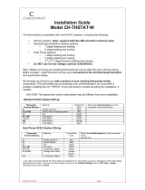
Standard Gas/Electric HVAC System Wiring
Single stage heating and cooling
R vs RC and RH Connections:
Single Transformer HVAC Systems. Typical modern central HVAC installations have a
integrated heating and cooling system with a single 24VAC transformer. For these systems,
there is only one 24VAC “R” wire and it can connect to either the RC or RH terminal on the
thermostat. The thermostat is supplied with an RC-RH jumper installed. Do not remove
the jumper for common transformer HVAC systems.
Separate Transformer HVAC Systems. Some installations may have separate heating
and cooling systems with separate 24VAC transformers. For those systems there will be a
separate “R” wire for the heating system (RH) and cooling system transformers (RC).
Take a
Picture!
*Note: the C wire (24V common) may not
be present.
If C wire is not present, the thermostat
must be powered by batteries.
If the C wire is present, you can power
DO NOT INSTALL BATTERIES
Mark the wires according to the terminal markings.
There may be additional wires such as Y2, W2
If you have RC and/or RH connections, see below.
Other wires are not used,
W
Y
G
C*
R
Connect the wires as marked from the HVAC
system to the corresponding terminals on the
thermostat back.
*C wire (24VAC common) may not be present.
If not, batteries must be installed.
Factory installed RC and RH jumper
Thermostat
Terminal Block
W2/O W1 RH C RC G Y1 Y2
Y
C*
R
W
G
Y
W
G
R
C*
Old thermostat wiring terminals
O/B
Heat Pump
Systems only
O

DCN: 140-02338 Rev 01 30419 Page 3
To connect separate transformer systems, FIRST REMOVE THE SUPPLIED RH-RC
JUMPER. Then connect the heating “R” wire to the RH terminal and the cooling “R” wire to
the RC terminal on the thermostat.
HEAT PUMP HVAC SYSTEMS WIRING
Single stage heating and cooling
Finish Wiring
• If you have additional wires for 2 stage systems (W2, Y2), see the wiring diagrams on
page 5 and 6.
• Check that the wires are screwed into the terminal blocks firmly.
• Gently pull on the wires to confirm the connection.
• Push all the excess wiring back into the wall.
Mount the thermostat
24VAC Powered Thermostat: If the thermostat is 24VAC powered (24VAC common “C”
wire is connected), DO NOT INSTALL BATTERIES!
• Install the thermostat on to the base.
• Turn on power to the HVAC system/thermostat.
Connect the wires as marked from the HVAC system to
the corresponding terminals on the thermostat back.
*C wire (24VAC common)
Heat Pump systems usually have the C wire connected
to the thermostat. If there isn’t a C wire, batteries must
be installed.
** O (Orange) or B (Brown) wire (changeover valve)
connect to the W2/O terminal on the thermostat.
NOTE: Be sure to set the correct changeover
operation (O = changeover with Cool, B =
changeover with Heat) in the SETUP menu.
Connect the R wire to either RC or RH terminal.
Factory installed RC and RH jumper. Do not remove.
O**
W
Y
G
C*
R
Thermostat
Terminal Block
W2/O W1 RH C RC G Y1 Y2

DCN: 140-02338 Rev 01 30419 Page 4
Battery Powered Thermostat: If the thermostat is battery powered (NO 24VAC common
“C” wire connected), install 4 NEW Alkaline AA batteries into the back of the thermostat.
• Install the thermostat on to the base.
• Turn on power to the HVAC system/thermostat.
Install batteries
Watch polarity!
+
+
+
+

DCN: 140-02338 Rev 01 30419 Page 5
Standard HVAC System
G Fan
W1 Heat Stage 1
Y1 Compressor Stage 1
R 24VAC Return
C 24VAC Common
Thermostat Connection
Y2 Compressor Stage 2
W2 Heat Stage 2
For single transformer systems,
connect R wire to either RC or RH
terminal. They are connected
together by the factory installed
jumper.
For systems with separate heating
& cooling transformers, connect
Heating R to RH and Cooling R to
RC. NOTE! REMOVE THE
FACTORY INSTALLED RC/RH
JUMPER.
Standard Gas/Electric HVAC System Wiring
Thermostat Setup:
Standard Gas/Electric HVAC Systems
For Single Stage Heat/Cool Systems:
Go to the Menu screen by pressing and holding the FAN button for 5 seconds
Press the down arrow to select the SYSTEM menu and press Select.
Set the following:
SYSTEM TYPE: Set to STANDARD
FAN TYPE: Set to GAS for typical gas furnace (fan is controlled by the furnace)
Set to ELECTRIC for electric heat (fan on with heat call)
For Two Stage Heat/Cool Systems:
Go to ADVANCED SYSTEMS SETTINGS menu.
From the Setup menu screen, press and hold the Fan and Down arrow buttons
for 5 seconds. Use the Down arrow button to select the following:
2ND STAGE HEAT ENABLE: Enable second stage heating output
If a single stage heating system, leave this set to N
If a 2 stage heating system, set to Y to enable.
2ND STAGE COOL ENABLE: Enable second stage cooling output
If a single stage cooling system, leave this set to N.
If a two stage cooling system, set to Y to enable.
Default Thermostat Setup:
Type: Standard HVAC
Fan Type: Gas Heat
1 Stage heating
1 Stage cooling
No Setup change required
for this configuration
Thermostat back
Typical thermostat wiring colors.
Caution: verify that original wiring
matches. Colors may be different.
Blue
Black/Brown
Red
White
Orange
Yellow
Green
C wire is not required for
battery operation.
C wire is required for 24VAC
operation.
W2/O
W1
24RH
24C
24RC
G
Y1
Y2
Factory Installed RC/RH jumper

DCN: 140-02338 Rev 01 30419 Page 6
G Fan
W1 Aux Heat
Y1 Compressor Stage 1
R 24VAC Return
C 24VAC Common
Y2 Compressor Stage 2
O Changeover Valve
Connect the R wire to either
the RC or RH terminal.
DO NOT REMOVE THE
RC/RH JUMPER
Heat Pump HVAC System
Thermostat Connection
Heat Pump HVAC System Wiring
Thermostat Setup:
Heat Pump HVAC Systems
For Single Stage Heat/Cool Systems:
Go to the Menu screen by pressing and holding the FAN button for 5 seconds
Press the down arrow to select the SYSTEM menu and press Select.
Set the following:
SYSTEM TYPE: Set to HEAT PUMP
CHANGE OVER: For changeover with cooling systems (Orange wire): set to WITH COOL (most common and default setting)
For changeover with heating systems (Brown wire): set to WITH HEAT
You must configure the thermostat’s changeover valve setting to work correctly with your HVAC system.
Check your system information to be sure and note the color of original thermostat wire and the terminal it was connected to.
No matter what the old stat connection was (O or B), connect the wire to the thermostats W2/O terminal.
For Two Stage Heat/Cool Systems:
Go to ADVANCED SYSTEMS SETTINGS menu. From the Setup menu screen, press and hold the Fan and Down arrow buttons
for 5 seconds. Use the Down arrow button to select the following:
AUXHEAT: If you have auxiliary heat strips, set this to Y to enable. (Default is Y)
2ND STAGE HEAT ENABLE: Enable second stage heating outputs
If a single stage heating system, leave this set to N
If a 2 stage heating system, set to Y to enable.
2ND STAGE COOL ENABLE: Enable second stage cooling outputs
If a single stage cooling system, leave this set to N.
If a two stage cooling system, set to Y to enable.
Note! If you get heating
when you expected cooling
or vice versa, change the
Change Over type to the
opposite setting.
Thermostat back
Black/Brown
Yellow
Green
Red
Blue
White
Orange
Typical thermostat wiring colors.
Caution: verify that original wiring
matches. Colors may be different.
Most Heat Pump systems
have the C wire and the
thermostat can be power by
the 24VAC from the HVAC
system.
Batteries are not required for
24VAC powered systems.
If there is not a C wire
installed, the thermostat
MUST be powered from
batteries
W2/O
W1
24RH
24C
24RC
G
Y1
Y2
Factory installed RC/RH jumper

DCN: 140-02338 Rev 01 30419 Page 7
Thermostat Setup: Configure for HVAC System
The thermostat must be set up for the correct HVAC system type and configuration for
proper operation.
Preset HVAC System settings
The thermostat is preset for the following typical HVAC system configuration:
• HVAC system type: Standard gas/electric
• HVAC fan type: Gas heat
• HVAC heating stages: one
• HVAC cooling stages: one
If the thermostat is installed on this type HVAC system, the System setup does not
need to be changed.
Installation is complete
For thermostats installed on a Heat Pump HVAC system or any HVAC configuration other
than the preset settings, the System settings need to be changed in the SYSTEM setup
menu to match the HVAC system.
Changing the HVAC System Setup
To change the thermostats HVAC system settings, first select the Menu Screen and then
select the SYSTEM menu. Follow instructions below to access the SYSTEM menu.
Note: To conserve battery life, the thermostat backlight turns off after a short time of no
activity. The first press of any button will turn on the backlight but will not initiate any
action other than turning on the backlight. Press the button again to initiate the action
desired. If the backlight is already on, button presses work with the first press.
Go to Menu Screen
From the Thermostat Main Screen, Press and Hold the “FAN” button until the Menu
screen is displayed.
To select the Menu
screen, press and
hold the FAN button
Main Screen

DCN: 140-02338 Rev 01 30419 Page 8
Thermostat Menu Screen
Menu options
When the thermostat Menu Screen is displayed, use the Up or Down arrow buttons to scroll
through the following options:
• SETUP (user preference settings)
• SYSTEM (HVAC system setup)
• ZWAVE (install/uninstall from Z-Wave network)
• HUMIDITY
• INFO (firmware versions and Z-Wave network information)
Select SYSTEM setup
To change the HVAC system default settings, scroll down to the SYSTEM menu item and
press “Select”.
SYSTEM setup menu
The SYSTEM menu is used to set up the thermostat for the correct HVAC system type.
• SYSTEM TYPE
• For Standard Gas/Electric systems, select “Standard”. This is the default
setting.
• For Heat Pump systems, use the Up/Dn arrows to change to “Heat Pump”
• Press Select to set.
• Press Done to exit
• FAN TYPE (For Standard HVAC systems only)
• Fan type depends on the heating system type.
• For Gas heat: select “GAS”. This is the default setting.
• For Electric heat: use the Up/Dn arrows to change to “ELECTRIC”.
• Press Select to set
• Press Done to exit
• CHANGEOVER TYPE (For Heat Pump HVAC systems only)
The changeover (or reversing) valve is used to change from heating to cooling operation. It
is either a changeover with cooling type (Orange wire) or changeover with heating type
(Brown wire). Most are changeover with cooling, which is the default setting.
Use the Up/Down
buttons to change
to the desired
menu item, then
press “Select”
Menu choices are
displayed in the
Status Display Line.
Press “Select” to
enter the selected
menu
Press “Done” to
exit back to the
Main Thermostat
Screen

DCN: 140-02338 Rev 01 30419 Page 9
• For Changeover with Cooling systems (Orange wire), select “WITH COOL”.
This is the default setting.
• For Changeover with Heating systems (Brown wire), use the Up/Dn arrows to
change to “WITH HEAT”.
• Press Select to set
• Press Done to exit
Not sure which Changeover type?
Check the existing thermostat connections to help determine this.
• If the original system had an orange wire connected to the “O” terminal, then this is a
“changeover with cool” system.
• If there was a brown wire connected to the “B” terminal, then this is a “change over
with heat” system.
• Set the Change Over setting accordingly. (Caution: These are typical wiring
colors/connections and may differ)
• If heating comes on when cooling is expected or vice versa, change the
“Change Over Type” to the opposite setting.
Advanced System Settings Menu
The Advanced System Settings Menu provides for addition system setup options.
These settings can affect system operation and should only be changed by qualified HVAC
installers.
To access the Advanced System Settings menu, first press and hold the Fan button to get
to the MENU screen. Continue to hold down the Fan button and press and hold the Down
Arrow button for 5 seconds. The first menu item in the Advance System Settings menu
“Display Lock”, will be displayed. Use the Up/Down arrow buttons to scroll through the
menu options to the desired setting. Press “Select” (Mode) button to change a setting.
Once it begins to flash, use the Up/Down buttons to select the desired setting. Press the
“Select” button to accept the new setting (flashing will stop).
Advanced Settings
Display Lock Range: Y or N Default: N
Y = Display LOCKED
N = Display UNLOCKED
Allows the thermostat buttons to be locked. When the buttons are locked, none of the
thermostat buttons will function as normal.
To unlock the thermostat, press and hold the FAN button for 5 seconds to access the
Setup screen (it’s the only button that works in the lock mode). Access the Advanced
Settings Menu (as above) to turn the Display Lock off.
Test Mode Range Y or N Default: N
Test mode shortens the system built-in delays (like MOT and MRT)
Y= Test mode on. Reduces all delays to 10 sec for quicker system testing
N= Test mode off. Normal system delays
Test mode will time out after 30 min and return to normal operation.
Aux Heat Enable (Heat Pump Systems only) Range: Y or N Default: Y
Enables the Auxiliary Heat operation.
Typically, the Aux Heat will be heat-strips in a Heat Pump system
Aux heat control is wired to the W1 terminal.

DCN: 140-02338 Rev 01 30419 Page 10
2nd Stage Heat Enable Range: Y or N Default: N
Enables the 2nd Stage Heat operation
2nd Stage Cool Enable Range: Y or N Default: N
Enables the 2nd Stage Cool operation
Minimum Run Time Range: 1- 9 Minutes Default: 3
Sets the Minimum Run Time (MRT) delay before a heating/cooling cycle can turn off.
Sets heating/cooling cycle time. Prevents rapid on/off cycling.
Minimum Off Time Range: 5-9 Minutes Default: 5
Sets the Minimum Off Time (MOT) delay before another heating/cooling cycle can begin.
Provides compressor short cycle protection. “WAIT” is displayed on screen when active.
Heat Setpoint Max Range: 30F to 109F (0C-43C) Default: 90F (32C)
Sets the maximum heating setpoint value.
Will not ramp or accept setpoints higher than this maximum.
Cool Setpoint Min Range: 33F to 112F (2C-45C) Default: 60F (15C)
Sets the minimum cooling setpoint value.
Will not ramp or accept setpoints lower than this minimum.
Heat Blower Off Delay Range: 0-90 seconds Default: 0 (off)
Sets the system blower delay off time after a heat call ends (fan purge).
Cool Blower Off Delay Range: 0-90 seconds Default: 0 (off)
Sets the system blower delay off time after a cool call ends (fan purge).
Heat - Cool Delta Range: 3 - 15 degrees. Default: 3F (1C)
Sets the minimum separation between heating and cooling setpoints.
SETPOINT PUSH
• Attempts to lower the cooling setpoint below the heating setpoint will PUSH the
heating setpoint down to maintain the heat/cool delta separation.
• Attempts to set the heating setpoint above the cooling setpoint will PUSH the cooling
setpoint up to maintain the setpoint heat/cool delta separation.
Heating Stage 1 On Threshold Range: 1 to 6 degrees Default: 1
Sets the delta from setpoint that stage 1 heating starts.
Heating Stage 1 Off Threshold Range: 0 to 5 degrees Default: 0
Sets the delta from setpoint that stage 1 heating stops.
Stage 1 turns off at setpoint + Delta Stage 1.
Heating Stage 2 On Threshold Range: 2 to 7 degrees Default: 2
Sets the delta from setpoint that stage 2 heating starts.
Heating Stage 2 Off Threshold Range: 0 to 6 degrees Default: 0
Sets the delta from setpoint that stage 2 heating stops.
Stage 2 turns off at setpoint + Delta Stage 2.
Aux Heat On Threshold Range: 3 to 8 degrees Default: 3
Sets the delta from setpoint that stage 3 heating starts.
Aux Heat Off Threshold Range: 0 to 7 degrees Default: 0
Sets the delta from setpoint that stage 3 heating stops.
Stage 3 turns off at setpoint + Delta Stage 3.

DCN: 140-02338 Rev 01 30419 Page 11
Cooling Stage 1 On Threshold Range: 1 to 7 degrees Default: 1
Sets the delta from setpoint that stage 1 cooling starts.
Cooling Stage 1 Off Threshold Range: 0 to 6 degrees Default: 0
Sets the delta from setpoint that stage 1 cooling stops.
Stage 1 turns off at setpoint - Delta Stage 1
Cooling Stage 2 On Threshold Range: 2 to 8 degrees Default: 2
Sets the delta from setpoint that stage 2 cooling starts.
Cooling Stage 2 Off Threshold Range: 0 to 7 degrees Default: 0
Sets the delta from setpoint that stage 2 cooling stops.
Stage 2 turns off at setpoint - Delta Stage 2.
Restore Defaults Range: Yes, No Default: No
Restores all settings to factory defaults.
Press Yes to restore defaults
Press No to exit and not restore defaults
Z-Wave Installation
See the Operating Guide for instructions on installing the thermostat on a Z-Wave network.

DCN: 140-02338 Rev 01 30419 Page 12
Operation Guide
Model TBZ500
24VAC or Battery Powered Z-Wave Thermostat
Backlight and Button Operation
The thermostat backlight is normally set to go out after 20 seconds of no button presses to
conserve battery power. If the backlight is off, the first button press of any button will
only turn on the backlight. Once the backlight is on, the buttons function normally.
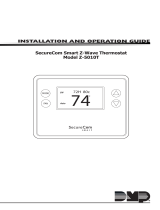
TBZ500 Display
Temperature Setting
Touch Buttons
Warmer
Cooler
Fan Mode
Selection
Heating/Cooling
Mode Selection
Room Temperature
Text Display Line
Backlit Display
Main Thermostat Screen
$$:$$$$~
Auto
On
Done
8$.5
Off
Heat-E
Cool
Auto
Select
123
FC
LOW BATT
Low Battery indicator
Display Lock indicator
Z-Wave Network Installed
indicator
Text Information Display Line
System Mode
indicators
Fan Mode
indicators
Button Mode Status
Mode Touch Buttons

DCN: 140-02338 Rev 01 30419 Page 13
System Operation Modes
displayed = System is ON and heating. If flashing, minimum run time (MRT) is active
displayed = System is ON and cooling. If flashing, minimum run time (MRT) is active
Stage Indicators
“1” = Stage 1 heating or cooling is ON
“2” = Stage 2 heating or cooling is ON
“3” = Stage 3 heating (Aux Heat) is ON
For Heat Pump systems only:
“Heat-E” = Emergency heat mode active
Setting the System Mode
System Modes
• Off: System is off. No heating or cooling will come on. If system was on, it will
turn off immediately.
• Heat: Only heating will occur.
• Cool: Only cooling will occur.
• Auto: Heating or cooling will come on according to the heating and cooling
setpoints. The system will automatically switch between heating and cooling
modes as needed to maintain the setpoints.
Special Heat Pump Mode: Emergency Heat
• Heat-E: An additional system mode, “Heat-E” for Emergency Heat will be
displayed if the HVAC System Type is set to Heat Pump. If there is a
compressor failure with the Heat Pump system, setting the mode to Emergency
Heat will allow the supplemental Aux Heat to come on first whenever there is a
call for heating. It also disables the compressor output to prevent further damage
to the HVAC system.
Caution! Emergency Heat should only be used for emergencies until the HVAC system
can be repaired. Running the system in Emergency Heat mode is commonly the most
expensive mode since only the electric heat strips are being used instead of the
more efficient heat pump compressor.
Press MODE
button to change
system mode

DCN: 140-02338 Rev 01 30419 Page 14
Setting the Heating or Cooling Temperature Setpoint
Setpoint Change
To change the setpoint, press the Up or Down arrow buttons. The screen will switch to the
setpoint change screen (as above) and show the current setpoint of the current heating or
cooling mode. Adjust setpoint temperature up or down with the arrow buttons.
Note! When in the Setpoint Change screen, pressing the MODE button will switch
the setpoint being displayed between the Heat and Cool setpoints.
Setpoint Push: The cooling setpoint cannot be set below the heating setpoint. The
thermostat will “push” the heating setpoint lower if the cooling setpoint is set below the
current heating setpoint. A 3 degree separation is maintained between the heating and
cooling setpoints. The same is true for raising the heating setpoint above the cooling
setpoint. The thermostat will “push” the cooling setpoint up to maintain the 3 degree
separation.
Lower Temperature
Raise Temperature
Press either Up or Down
arrow button to go to the
Setpoint Change screen
Setpoint Change screen
Press “Done” (FAN button) to set the setpoint and exit back to the main
thermostat screen or wait for the screen to automatically time out.
Press the Up or Down arrow
buttons to set the desired
temperature setpoint
Pressing the Up or Down
buttons will change the
setpoint 1 degree. Press and
hold the button to ramp the
setpoint.
Setpoint being changed
Press MODE
button to change
from the heat
setpoint to the
cool setpoint

DCN: 140-02338 Rev 01 30419 Page 15
Setting the Fan Mode
Thermostat Menu Mode
The Thermostat has a menu of setup and information displays.
To change to the Menu Mode, press and hold the FAN button for 5 seconds.
The display will change to the Menu Mode and display the Setup screen.
Use the Up/Down arrow buttons to scroll through other menu items.
Thermostat Main Screen
Press the FAN button to change the Fan mode
Fan Modes:
• Auto: Fan automatically operated by the HVAC system. (normal setting)
• On: Manual Fan mode. Fan stays on until mode is changed back to Auto,
independent of the heating or cooling system operation.
Press and hold the
FAN button for 5
seconds to go to
the Menu Mode
screen

DCN: 140-02338 Rev 01 30419 Page 16
Menu Mode Screen
Menu Mode options
• SETUP User preference settings
• SYSTEM Thermostat HVAC system settings
• ZWAVE Z-Wave network install or remove
• INFO Displays thermostat version and setup info
SETUP Menu
User preference settings.
FAHRENHEIT or CELSIUS. Select the temperature display mode.
BACKLIGHT TIMEOUT. Sets the time from last button press that the backlight will turn off.
Range:10-30 seconds. Note: long backlight timeouts will reduce battery life.
If the thermostat is powered from 24VAC, the backlight timeout can be set to “0” which will
keep the backlight on continuously.
TEMPERATURE SENSOR CALIBRATION. Change the temperature calibration by +/- 7
degrees. Use the Up/Dn arrow buttons to change to the desired temperature displayed.
HUMIDITY SENSOR CALIBRATION. Change the humidity calibration by +/- 7 percent.
Use the Up/Dn arrow buttons to change to the desired humidity displayed.
STATUS LINE Display. Select Setpoints or Humidity to be displayed on the upper status
line.
SYSTEM Menu
SYSTEM TYPE. Select the system type, STANDARD or HEAT PUMP
FAN TYPE (Standard systems only).
Select fan type: GAS (typical default setting) or ELECTRIC
CHANGE OVER TYPE (Heat Pump systems only).
Select the Changeover type:
Use the
UP/DOWN
buttons to select
the desired menu
item
Press “Select”
to go to the
selected menu
item screen
Press “Done” to
go back to the
Thermostat
Main Screen
Menu item display

DCN: 140-02338 Rev 01 30419 Page 17
Changeover WITH COOL (typical default setting)
Changeover WITH HEAT
See Installation Guide for more information on System setup and the Advanced Systems
Menu
Z-WAVE Menu
This menu item allows the thermostat to be enrolled to the Z-Wave network. Follow the
instructions shown in the Z-Wave® Operation section (page 18) to enroll the Thermostat
onto the network.
INFO Menu
The INFO menu displays information about the thermostat. Use the Up/Dn buttons to scroll
through the various items.
Thermostat information displayed:
VERSION Thermostat firmware version
ZWAVE Z-Wave firmware version
NODE ID Z-Wave Node ID
HOME ID Z-Wave Home ID
SYSTEM TYPE displays current System Type settings (Standard or Heat Pump)
If System Type = Standard
FAN TYPE displays current Fan Type setting
If System Type = Heat Pump
CHANGEOVER TYPE displays current Change Over valve (reversing valve) setting
AC or Battery Powered: AC POWER will be displayed if power by 24VAC
Thermostat Operation
Minimum Run Time (MRT)
The thermostat has a Minimum Run Time (MRT) delay after the start of any heating or
cooling call. This minimum run time assures even heating and cooling cycles. The MRT
will keep the system on, even if it reaches the setpoint room temperature, or you change
the setpoint to a temperature that would satisfy the call, until the MRT expires. Changing
the Mode to OFF will cancel the MRT and the system will turn off immediately. The MRT
can be adjusted in the Advanced Settings menu of the thermostat.
Note: When MRT is active, the heating or cooling icon will be flashing.
Minimum Off Time (MOT)
The thermostat has a Minimum Off Time (MOT) delay after any heating or cooling cycle
ends. This delay prevents rapid heating/cooling cycles and also provides “short cycle
protection” for the system compressor. This delay may be noticeable when you change a
setpoint and it does not respond immediately due to the MOT delay timer preventing the
system from restarting. The MOT delay time can be adjusted in the Advanced Settings
menu of the thermostat but there is a minimum of a 5 minute delay to assure compressor
protection.
Note: When MOT is active, the thermostat Status Display shows “WAIT”.

DCN: 140-02338 Rev 01 30419 Page 18
Z-Wave® Operation
This product can be operated in any Z-Wave network with other Z-Wave certified devices
from other manufacturers. All mains operated nodes within the network will act as repeaters
regardless of vendor to increase reliability of the network.
Thermostat Battery Operation: If the thermostat is installed in a Z-Wave network while
powered by batteries, it will be enrolled as a Z-Wave FLiRs type device. This is a power
saving mode that conserves the batteries by keeping the radio asleep most of the time.
However, in this mode, the thermostat does not act as a repeater/router in the Z-Wave
network.
Thermostat 24VAC Operation: If the thermostat is installed in a Z-Wave network while
powered by 24VAC, it will be enrolled as an always-listening device and can act as a router
node in the Z-Wave network.
Caution! Once installed in a Z-Wave network, if you change how the thermostat is
powered (from batteries to 24VAC or vice versa), you must remove and re-enroll the
thermostat in the Z-Wave network for it to work correctly.
Adding the thermostat to a Z-Wave network.
SmartStart Inclusion
The TBZ500 is SmartStart enabled and can be added into a Z-Wave network by scanning
the Z-Wave QR Code present on the product with a controller providing SmartStart
inclusion. No further action is required and the SmartStart product will be added
automatically within 10 minutes of being switched on in the network vicinity.
The SmartStart QR code can be found on the back of the thermostat, side of the package,
or also inserted as an insert card/sticker. The sticker contains the full DSK string. It’s
important that if you plan to use DSK that you keep this label in a safe place you’ll
remember.
If your system does not support SmartStart, you can still enroll your thermostat using
classic inclusion.
Classic Inclusion
1. Follow the instructions provided with your system for enrolling the thermostat.
2. Press and hold the FAN button on the Thermostat until the screen changes to
the Menu screen.
3. Press the UP button until ZWAVE is shown in the Status Display line then press
Select.
4. INSTALL should be shown on the status line.
5. When instructed by your system installation to add the thermostat to the network
press the “Select” button to install. Wait until SUCCESS or FAILED is shown on
the status display.
6. Press Done on the Thermostat to exit the ZWAVE screen.
7. Press Done on the Thermostat again to exit the Menu screen.
8. Once enrolled on your system’s network, continue to follow the instructions
provided to complete the enrollment and naming of the thermostat.
9. The indicator should be shown on the Thermostat Main screen indicating
the thermostat has successfully been enrolled into the Z-Wave network.

DCN: 140-02338 Rev 01 30419 Page 19
Removing the thermostat from a Z-Wave network.
It may be necessary to remove and/or reinstall the thermostat from a Z-Wave network if the
thermostat has been previously installed on another network.
Follow the instructions supplied with your Z-Wave system to remove/uninstall a Z-Wave
device. When the system instructs you to press and release the Z-Wave button on the
thermostat, follow these steps:
1. Press and hold the FAN button for 3 seconds until the Menu screen is displayed.
2. Press the UP arrow button to scroll to the “ZWAVE” menu.
3. Press “Select” to select the ZWAVE screen.
4. The display will show “REMOVE” in the text line.
5. Press “Select” to perform the remove action.
6. “WAIT” will be displayed in the text line. The remove operation is in process.
7. “SUCCESS” will be display when the reset is completed.
8. Press “Done” to exit back to the thermostat screen.
9. Thermostat is now ready to be added to the wireless network.
Factory Reset
Please use this procedure only when the Z-Wave Primary Controller is missing or
otherwise inoperable.
To reset the TBZ500’s Z-Wave parameters to Factory Settings (both Z-Wave and HVAC
settings):
1. Remove power from the TBZ500.
2. Restore power to the TBZ500.
3. When “TBZ500” appears on the screen, hold down the MODE and FAN buttons
at the same time.
4. Release the buttons when RESET appears on the Status Line.
5. Once the TBZ500 resets the Z-Wave and HVAC settings, a DONE confirmation
message will appear on the screen before the thermostat self-reboots.

DCN: 140-02338 Rev 01 30419 Page 20
FCC/IC
INFORMATION TO USER
This device complies with Part 15 of the FCC Rules. Operation is subject to the following
two conditions: (1) This device may not cause harmful interference, and (2) This device
must accept any interference received, including interference that may cause undesired
operation.
This equipment has been tested and found to comply with the limits for Class B Digital
Device, pursuant to Part 15 of the FCC Rules. These limits are designed to provide
reasonable protection against harmful interference in a residential installation. This
equipment generates and can radiate radio frequency energy and, if not installed and used
in accordance with the instructions, may cause harmful interference to radio
communications. However, there is no guarantee that interference will not occur in a
particular installation. If this equipment does cause harmful interference to radio or
television reception, which can be determined by turning the equipment off and on, the user
is encouraged to try to correct the interference by one or more of the following measures.
• Reorient or relocate the receiving antenna
• Increase the separation between the equipment and receiver
• Connect the equipment into an outlet on a circuit different from that to which the
receiver is connected
• Consult the dealer or an experienced radio/TV technician for help
Any changes or modifications not expressly approved by the party responsible for
compliance could void the user’s authority to operate the equipment.
This device complies with Industry Canada license-exempt RSS standard(s). Operation is
subject to the following two conditions: (1) this device may not cause interference, and (2)
this device must accept any interference, including interference that may cause undesired
operation of the device.
Le présent appareil est conforme aux CNR d'Industrie Canada applicables aux appareils
radio exempts de licence. L'exploitation est autorisée aux deux conditions suivantes : (1)
l'appareil ne doit pas produire de brouillage, et (2) l'utilisateur de l'appareil doit accepter
tout brouillage radioélectrique subi, même si le brouillage est susceptible d'en
compromettre le fonctionnement.
/