Page is loading ...

OUR EDGE IS OUR PRODUCT
800 SERIES HEAVY DUTY
SERVICE MANUAL
65,000 – 100,000 LB
PART# EDOC002
CHALMERS SUSPENSIONS INTERNATIONAL INC
6400 NORTHAM DRIVE, MISSISSAUGA
ONTARIO, CANADA
L4V 1J1
(905) 362-6400 VOICE (905) 362-6401 FAX

i
Contents
Page No.
1.0 GENERAL INFORMATION……………………………………… 1
2.0 INTRODUCTION TO THE SUSPENSION……………………… 2
2.1 SUSPENSION PART NAMES……………………………… 2
3.0 SERVICE – INSPECTION REQUIREMENTS…………………. 5
4.0 GUIDELINE TO THE INSPECTION AND
REPLACEMENT OF SERVICE PARTS…………………………. 7
4.1 FASTENERS………………………………………………….. 8
4.2 TORQUE ROD BUSHING INSPECTION…………………. 9
4.3 TORQUE ROD BUSHING REPLACEMENT……………… 11
4.4 RESTRICTOR CAN INSPECTION………………………… 15
4.5 RESTRICTOR CAN REPLACEMENT…………………….. 15
4.6 SPIGOT CAP INSPECTION………………………………… 17
4.7 SPIGOT CAP REPLACEMENT……………………………. 17
4.8 WALKING BEAM INSPECTION…………………………. 18
4.9 WALKING BEAM REPAIR/REPLACEMENT…………… 19
4.10 SADDLE INSPECTION……………………………………. 21
4.11 RUBBER SPRING INSPECTION…………………………. 22
4.12 RUBBER SPRING REPLACEMENT……………………….. 23
5.0 AXLE ALIGNMENT……………………………………………….. 23
5.1 AXLE MEASUREMENT…………………………………… 24
5.2 AXLE ALIGNMENT ADJUSTMENTS…………………… 27
6.0 TROUBLE SHOOTING………………………………………….. 29

ii
APPENDIX “A”……………………………………………………. 32
APPENDIX “B”……………………………………………………. 33
APPENDIX “C”……………………………………………………. 36

1
1.0 GENERAL INFORMATION
This manual is to be used for the service of a Chalmers 800 Series Tandem Suspension
65,000 to 100,000 lbs capacity and is intended to give guidance and recommendation for
the care, maintenance, inspection and safe operation of the above suspension. It is not a
replacement for existing or future specific Pre-Delivery Inspection (P.D.I.) &
Preventative Maintenance Programs.
Before proceeding with any work on or with the suspension, please read this manual
completely to familiarize yourself with the maintenance and operation of the Chalmers
Suspension.
TAKE SPECIAL NOTICE of procedures 1.1 through 1.6 that must be followed without
exception when working on any procedures described in this manual.
1.1 ALL CHALMERS FASTENERS must be torqued to the specific values shown in
Table 2 and to the specific period shown on the Service Inspection Requirements
Section 3.0.
**IMPORTANT – Failure to check torque, may lead to fastener failure and
consequent loss of vehicle control and void warranty.
1.2 DO NOT USE ANY mineral based oils, greases, jellies, or solvent soaps as a
lubricant to aid in the assembly of the rubber bushed torque rods. Use only
quality rubber lubricants. Failure to do so will void warranty.
1.3 DO NOT AT ANY TIME WORK AROUND OR UNDER A VEHICLE
SUPPORTED ONLY ON LIFTING DEVICES. THE VEHICLE MUST BE
SECURELY CHOCKED AND SUPPORTED ON RIGID STANDS BEFORE
WORK MAY COMMENCE.
1.4 ALL RELEVANT, MACHINERY, TOOL AND WORK PLACE SAFETY
procedures and instructions must be followed without exception when working on
any procedures described in this manual.
FAILURE TO ADHERE TO ANY SAFETY PROCEDURES OR
INSTRUCTIONS, MAY LEAD TO PERSONAL INJURY.
1.5 USE ONLY CHALMERS APPROVED REPLACEMENT PARTS. Tests have
shown alternate parts, particularly torque rod bushings, do not meet the
performance expectations or engineering criteria established for the original
products. This has created extreme hard part wear or hardware failures with
consequent loss of warranty and more important loss of vehicle control.
1.6 DO NOT operate the vehicle with the suspension in an over loaded condition.
Operating at a gross rear axle weight (GRAW), which exceeds the rated
suspension capacity will lead to a suspension failure with consequent loss of
vehicle control and void warranty.

2
2.0 INTRODUCTION TO THE SUSPENSION
The Chalmers 800 Series Rear Suspension is a walking beam-type tandem axle
suspension that uses hollow rubber springs instead of leaf springs or air bags. Each
hollow rubber spring is mounted between a frame-rail plate and the centre (front-to-rear)
of the steel walking beam. A hanger bracket assembly is attached to the frame and
provides mounting points for the lower torque rods that tie the axles to the frame. The
upper torque rods are fastened to brackets that bolt to the frame side rails and to tower
assemblies that are welded to the top of the differential housings. See Fig.1.
The 800 Series Rear Suspension allows a high degree of both parallel and diagonal
articulation, while maintaining wheel load equalization to within 3%.
The Chalmers suspension design separates the rear suspension’s responsibility for
supporting/cushioning the load from that of locating/guiding the axles. The suspension is
very light, relative to its load carrying capacity and requires very little maintenance. In
fact, there are no lubrication fittings since grease and oil are never needed.
The 800 Series is available in 60” and 65” axle spacing for the 65,000 lbs capacity and in
65” axle spacing for the 80-100,000 lbs capacity. The axle spacing and capacity is
included as part of the suspension name, e.g. “Chalmers 860-65 Suspension” or Chalmers
865-100 Suspension.
The rear suspension may be precision-aligned by adjusting the length of the lower torque
rods. These rods have both left and right hand threads cut on the same tube so rotating
the tube changes the effective length of the tube.
2.1 SUSPENSION PART NAMES
Fig.1A shows an exploded view of a typical 800 Series Suspension 65,000lbs capacity.
Fig.1B shows an exploded view of a typical 800 Series Suspension 80-100,000 lbs
capacity.
Throughout this manual, parts will be referred to by the names shown on this figure.

3
SUSPENSION NOMENCLATURE
FIGURE 1A
(65,000 lbs suspension shown)

4
SUSPENSION NOMENCLATURE
FIGURE 1B
(80-100,000 lbs suspensions shown)

5
3.0 SERVICE – INSPECTION REQUIREMENTS
The Chalmers 800 Series Suspension was designed to require minimum general
maintenance. The recommendations shown on the following chart are precautionary and
are aimed at avoiding future problems.
PART
ACTION
P.D.I.
1000 Mile
1600 KM
DLY
MTH
YRLY
All Hardware
Check torque to values shown on
Table 2.
On the daily walk around
Visually inspect for looseness.
.
.
.
.
Torque Rod
Bushing
Wear check. See Section 4.2 for
guidelines.
Visually inspect for tears or cracks.
Visually inspect for correct
installation. See Sections 4.2 & 4.3
for guidelines.
.
.
.
.
Restrictor
Can
Visually inspect for wear or
cracking. Replace as required. See
Sections 4.4 & 4.5 for guidelines.
Visually inspect for missing cans,
and cans not centered on spring.
.
.
Spigot Cap
On the daily walk around visually
inspect for missing, cracked, broken
or loose caps. Replace as required or
retorque. See Sections 4.6 & 4.7 and
Table 3 for guidelines.
.
.
.

6
PART
ACTION
P.D.I.
1000 Mile
1600 KM
DLY
MTH
YRLY
Walking
Beam
Inspect for wear and cracks. See
Sections 4.8 & 4.9 for guidelines.
Inspect for beam free float in axle
saddles, 1.75” (45mm) fore and aft.
.38” (10mm) side to side. See
Section 4.8.
.
.
Saddle
Inspect for wear. See Sections 4.10
for guidelines.
.
Axle Bracket,
Hanger
Bracket Assy
Visually inspect for road damage or
cracks. Replace any damaged parts
as required. Contact Chalmers for
guidelines.
.
.
Rubber
Spring
Visually inspect for chemical
damage, deep tears and deformed
springs. Replace as required. See
sections 4.11 & 4.12 for guidelines.
Visually inspect that the spring is
sitting centrally on the spring plate
and is seated down fully.
.
.
.
NOTICE:
The above chart was developed from Chalmers experience on parts subject to wear in normal
service. The wear rate is dependent on a number of factors such a load carried, speed travelled,
roadbed conditions, traffic density and number of stops.
NOTE:
IF THE OPERATOR OF THE VEHICLE IS IN ANY DOUBT ABOUT THE SAFETY OF
THE SUSPENSION, HE SHOULD NOT OPERATE THE VEHICLE AND SHOULD
IMMEDIATELY SEEK QUALIFIED ADVICE.

7
4.0 GUIDELINES TO THE INSPECTION AND REPLACEMENT OF SERVICE
PARTS
Recommended tools needed to carry out the work covered in Section 4.1 through 4.13.
TOOL LIST
Open End Wrench: 9/16”, 3/4”, 15/16”, 1-1/8”, 1-5/16”
Box Wrench (Offset Preferred): 9/16”, 3/4”, 15/16”, 1-1/8”, 1-5/16”.
Standard Socket (1/2” Drive): 9/16”, 3/4”, 15/16”, 1-1/8”, 1-5/16”.
Extra Deep Socket (1/2” Drive): 15/16”.
Impact Socket (1/2” Drive): 9/16”, 3/4”, 15/16”, 1-1/8”, 1-5/16”.
Extra Deep Impact Socket (1/2” Drive): 15/16”.
Torque Wrench (1/2” Drive): 25 – 250 Ft. Lbs. (CALIBRATED)
GENERAL TOOLS
Socket Drive Ratchet (1/2” Drive)
Heavy Mallet (Rubber, Copper or Hide)
2 lbs. Copper/Hide Hammer
Large (12” Long Min.) Square Blade Screwdriver
Pinch or Wrecking Bar (3/4” size)
Tape Measure (16 ft.)
Vernier Caliper (6.0” Reading .001”)
Impact Wrench (1/2” Drive)
Bottle Jack (5 ton)
Wheel Chocks
Various Wooden Blocks
LUBRICANTS
Rubber Lubricant: Rimslip or equivalent
Important – Do not use oil or grease.

8
4.1 FASTENERS
This guideline is to be used for the inspection or replacement of Chalmers
supplied fasteners ONLY. Not supplied by Chalmers are the fasteners attaching
the triangular frames and upper frame brackets to the vehicle frame. For
inspection and specification on these, please refer to the vehicle manufacturer.
The fastener systems used in a Chalmers suspension are the key to the care and
safe operation of the suspension.
These systems comprise of an SAE GR.8 flanged head bolt and SAE GR.G
flanged head “Stover” locknut. The sizes of these systems have been specifically
engineered for each of their positions and functions within the suspension. See
the following Table 1 for size and function.
TABLE 1
SIZE CAPACITY FUNCTIONS
3/4" Dia. 65,000
to
80,000
Tower to Tower Adapter Assembly
5/8” Dia. 65,000
to
100,000
ALL Torque Rod Joints &
Torque Rod Eye Pinch Bolts*
Spring Plate to Beams
3/8” Dia. 65,000
to
100,000
Rebound Stop to Hanger Bracket
Assembly
* Single pinch bolt style
For the safety and proper operation of the suspensions ALL FASTENERS MUST, using
a calibrated torque wrench, be initially torqued and retorqued at 1000 miles/1600 km of
service, to the specific values shown on Table 2.

9
TABLE 2 Torque Specifications
For Bolts and Locknuts provided by Chalmers
BOLT SIZE ASSEMBLY TORQUE FT. LBS.
3/8” 35
1/2" 65
5/8” 135
3/4” 250-280*
* Value for tower to tower adapter assembly. For all other uses contact Chalmers Suspensions.
The above torques are recommended for Chalmers-supplied hardware only, and are
NOT intended for hardware supplied by others.
NOTE: Re-torque must be done to both original and replacement fasteners.
IMPORTANT: For fastener replacement use ONLY NEW CHALMERS
approved fasteners. DO NOT RE-USE or use other fasteners.
To do so may lead to fastener failure and consequent loss of
vehicle control.
IMPORTANT: FAILURE TO CHECK TORQUE MAY LEAD TO
FASTENER FAILURE AND CONSEQUENT LOSS OF
VEHICLE CONTROL.
4.2 TORQUE ROD BUSHING INSPECTION.
All 800 Series Suspensions incorporate rubber bushed torque rod joints that isolate the
vehicle from axle braking and driving shocks. The Chalmers bushings absorb axle shock
by compression. This compression may give a false impression of a worn bushing. To
reduce the chances of prematurely replacing a good bushing, the following steps should
be used when inspecting all Chalmers bushings:
STEP 1 - If possible power wash the torque rod ends. As a minimum, the ends should be
brushed with a hard bristle brush to remove road dirt accumulations so that the rubber
bushing may be seen.
STEP 2 – Chock the front tires to prevent the vehicle from moving. Remove all drive
axle brake or wind up loads by placing transmission in neutral, releasing spring brakes, or
driveline brake.
STEP 3 – USING HANDS ONLY attempt to move the torque rod ends, checking
for FREE play. If free play is felt, the bushing should be replaced. (If in doubt contact
Chalmers).
NOTE: DO NOT USE A PRY BAR OR LEVER to check for free play. To do so may
lead to premature bushing replacement.

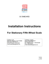
10
SPIGOT JOINTS
FIGURE 2
N
UMBER “2” JOINT
ASSEMBLY
STANDARD BASE
N
UMBER “2” JOINT
ASSEMBLY
HEAVY DUTY BASE
Item Part No. Description
1 800021 Spigot Base #2 Joint
2 800055 Spigot Cap #2 Joint
3 800010 T/Rod Bushing #2 Joint
* 3A 800009 T/Rod Bushing-Oversize #2 Joint
4 02P00141 Spigot Base H/D #2 Joint
* Service Bushing
#2 Joint (800021 Base)
800 Series Tandem Truck 65,000 lbs. Capacity (all
Rods) & 80-100,000 lbs. Capacity (upper Rods).
#2 Joint (02P00141 Base)
800 Series Tandem Truck 80-100,000 lbs. Capacity
(lower Rods).

11
4.3 TORQUE ROD BUSHING REPLACEMENT
Replacement of Chalmers Torque Rod Bushings may be achieved easily and quickly in
any shop without the use of a press or special tools, using the following steps as a guide.
STEP 1 – If possible power wash the torque rod ends, as a minimum, the ends should be
brushed with a hard bristle brush to remove road dirt accumulations.
STEP 2 – Chock the front tires to prevent the vehicle from moving. Remove all drive
axle brake or wind up loads by placing transmission in neutral and releasing the spring or
driveline brakes.
STEP 3 – Lift the rear of the vehicle. Support the frame on stands so all weight is just
taken off the suspension.
NOTE: All stands and lifting devices MUST be of sufficient strength and rigidity to
safely support the vehicle. DO NOT WORK AROUND OR UNDER THE VEHICLE
WHEN SUPPORTED ON LIFTING DEVICES.
STEP 4 – Work on only one torque rod at a time. Remove the 5/8” NC joint fasteners
and spigot caps. Discard the fasteners, keep the spigot caps for inspection and cleaning.
Remove the torque rod from the spigots by prying at each end until it comes free of the
spigots.
NOTE: By completely removing and re-fitting only one torque rod at a time the chance
of torque rod mix-up, which could lead to re-alignment of the suspension, or loss of axle
planning angle and consequent axle damage, will be eliminated.
STEP 5 – Place the torque rod on a bench or the floor with the bushing end facing up.
Remove the bushings by inserting the tip of a large screwdriver down between the
bushing and the torque rod eye and prying out. Discard the bushing.
STEP 6 – Using a wire brush and/or scraper clean all rust, scale and rubber
accumulations from the spigots, torque rod eyes and spigot cap, taking particular care to
clean the inside taper of the spigots.
STEP 7 – Inspect the torque rod eyes, spigots and spigot caps for visual cracks and wear.
Should any of the following parts show visual cracks, the part MUST be discarded and
replaced:
- Torque Rod and Eye
- Spigot Cap
Should the spigot show visual cracks, contact Chalmers for guidelines.
For wear limits, refer to Table 6. Chalmers allows for wear in its design by providing
oversize replacement bushings for the 65,000 lbs. to 100,000 lbs. Suspensions. Refer to
Table 6 for when to use.

12
STEP 8 – Liberally lubricate the inside diameter of the torque rod eye, and the outside
diameter of the replacement rubber bushing with a quality rubber lubricant such as
Rimslip or equivalent.
IMPORTANT: Never use any mineral based oils, greases, jellies or solvent soaps as a
lubricant. To do so will lead to the premature failure of the bushing.
Place the torque rod on a solid level floor with the open eye end up. Place a rubber
bushing onto the eye so as the outside tapered end of the bushing just enters the eye. Try
to make sure the bushing is as even as possible to the eye. With a heavy, soft-faced
mallet, quickly strike the bushing to drive it down into the eye. See Fig.3.
FIGURE 3
NOTE: Repeat the above procedure for the 2nd bushing. Then, flip the torque rod over
180 degrees. Tap with a mallet to drive the bushings completely through the eyes until
they are positioned evenly in the eyes. See Fig.3.
STEP 9 – Liberally lubricate the torque rod rubber bushings and the relevant spigots with
a quality rubber lubricant.
IMPORTANT: Never use any mineral based oils, greases, jellies or solvent soaps as a
lubricant to aid in the assembly of the rubber bushed torque rods. To do so will lead to
the premature failure of the bushing.
STEP 10 – Push each end of the torque rod onto its relevant spigot. Using a heavy soft-
faced mallet, drive the toque rod onto the spigots. For best results, alternate end to end
driving so as the torque rod bushings travel evenly over the spigots. Continue driving
until the bushing contacts the spigot bottom face.

13
STEP 11 – Press the spigot caps into the ends of the torque rod bushings, secure the ends
in place using new 5/8” NC fasteners.
Torque the 5/8” NC fasteners to 135 ft. lbs. See Table 2.
**IMPORTANT: Failure to check torque may lead to fastener failure and consequent
loss of vehicle control and void warranty.
Repeat Steps 1 through 11 for each torque rod to complete the suspension rebushing.
IMPORTANT: USE ONLY NEW CHALMERS approved 5/8” NC fasteners for the
joints. DO NOT RE-USE or use other fasteners. To do so may lead to fastener failure
and consequent loss of vehicle control and void warranty.
When finished rebushing, check to see if the torque rods have been replaced as per Fig.4.

14
TORQUE ROD INSTALLATION
FIGURE 4
65,000 LBS
CAPACITY
SUSPENSION
80,000 to 100,000 LBS
CAPACITY
SUSPENSION
UPPER TORQUE RODS #805131
UPPER TORQUE RODS #05S00004

15
4.4 RESTRICTOR CAN INSPECTION
The Chalmers spring system comprises of a rubber spring and an enclosing metal
restrictor can. The purpose of the restrictor can is to provide specific ride, road handling
characteristics and protection to the spring.
To accommodate the different road handling conditions that may be encountered,
Chalmers produces a number of different sized restrictor cans. Refer to Appendix “A”
for application guidelines.
The free floating design of the Chalmers spring and beam, requires that the restrictor can
be free to move on the vehicle frame. The restrictor can will wear or corrode over a
period of time and will require replacement. Carefully inspect the restrictor can for
cracks or severe corrosion, using the following steps as a guideline:
STEP 1 – If possible, power wash the restrictor can spring area. As a minimum, brush
the area with a hard bristle brush to remove road dirt accumulations.
STEP 2 – Chock the front tires to prevent the vehicle from moving. Lift the rear of the
vehicle, support the frame on stands so that all weight is just taken off the suspension.
NOTE: All stands and lifting devices, MUST be of sufficient strength and rigidity to
safely support the vehicle. DO NOT WORK AROUND OR UNDER THE VEHICLE
WHEN SUPPORTED ON LIFTING DEVICES.
STEP 3 – Rotate the restrictor can completely around, looking at the top and sides for
visual cracks and signs of severe corrosion or distortion. If any of these are present, or
the restrictor can is missing, it should be replaced. It is recommended that both restrictor
cans be replaced to assure evenness of ride and handling.
NOTE: Should a cracked or missing restrictor can be found during vehicle operation, it
may be driven SLOWLY to the nearest maintenance shop for replacement.
ALL CRACKED OR MISSING restrictor cans MUST be replaced. Failure to do so may
lead to loss of vehicle control and consequent personal injury.
4.5 RESTRICTOR CAN REPLACEMENT
Replacement of Chalmers restrictor cans may be achieved easily and quickly in any shop
without the use of special tools, using the following steps as a guide.
STEP 1 – If possible, power wash the restrictor can spring area. As a minimum, brush
the area with a hard bristle brush to remove road dirt accumulations.
STEP 2 – Chock the front tires to prevent the vehicle from moving. Lift the rear of the
vehicle, support the frame on stands so as all weight is just taken off the suspension.

16
NOTE: All stands and lifting devices MUST be of sufficient strength and rigidity to
safely support the vehicle. DO NOT WORK AROUND OR UNDER THE VEHICLE
WHEN SUPPORTED ON LIFTING DEVICES.
STEP 3 – Remove the four (or three) 5/8” NC fasteners holding the lower spring plate to
the beam. Discard the fasteners.
STEP 4 – Pull the lower spring plate, spring and restrictor can as one assembly outward
off the beam. See Fig.5.
FIGURE 5
STEP 5 – Separate the restrictor can, spring and lower spring plate. Discard the restrictor
can. Using a wire brush or scraper, remove rust and road accumulations from the spring
plate. Clean out the centre vent holes in the beam and lower spring plate. See Fig.5.
Inspect the lower spring plate for visual cracks. If cracked, replace. Contact Chalmers
for details.
STEP 6 – Turn the spring upside down so as the old top is now down. Place on lower
spring plate, inserting the spring dowel into the centre spring hole. Place the replacement
restrictor can over the spring. Make sure the can centre locator is in the centre spring
hole. See Fig.5.
STEP 7 – Lift and place as one assembly, the lower spring plate, spring and restrictor can
onto the beam. Line up the 5/8” fastener holes.
STEP 8 – Install and tighten the new 5/8” NC spring plate fasteners. Torque to 135 ft.
lbs. See Table 2.
STEP 9 – Repeat Steps 3 through 8 to complete. Before removing vehicle from stands,
check both restrictor cans for an even gap around the spring. Adjust if required.
Standard
Spring
Plate
Mounting
3 Point
Spring
Plate
Mounting

17
4.6 SPIGOT CAP INSPECTION
The spigot caps are part of the Chalmers torque rod joint system and play a key part in
this system by placing a small amount of end compression to the rubber bushing and
providing end retention to the joint.
The suspension capacity and spigot cap used is shown in the following Table 3.
TABLE 3
JOINT SIZE CAPACITY SPIGOT CAP NO. BUSHING
O.E.M SERVICE
#2 65,000 lbs.
100,000 lbs.
800055 800010 800009
Visual inspection of the spigot caps should be done on a daily basis. See Section 3.0
Service Inspection Requirements.
IMPORTANT: If a missing, cracked or broken spigot cap is detected, it MUST be
replaced immediately. DO NOT operate the vehicle. To do so may lead to consequent
loss of vehicle control and personal injury.
IMPORTANT: If a loose spigot cap is found, retorque the 5/8” NC fasteners to 135 ft.
lbs. See Table 2. Should persistent loosening occur, replace the 5/8” NC fastener as hard
part wear is affecting the bolt seat
4.7 SPIGOT CAP REPLACEMENT
Replacement of the spigot caps may be achieved easily and quickly with no requirements
to remove major parts from the vehicle or use special tools, using the following steps as a
guide.
STEP 1 – If possible power wash the torque rod ends. As a minimum, the ends should be
brushed with a hard bristle brush to remove road dirt accumulations.
STEP 2 – Chock the front tires to prevent the vehicle from moving. Remove all drive
axle brake or wind up loads by placing transmission in neutral and releasing, the spring or
driveline brakes.
STEP 3 – Remove the 5/8” NC fasteners and pry off the spigot cap, discard both.
STEP 4 – Press the replacement spigot cap into the ends of the torque rod bushings.
STEP 5 – Install and tighten new 5/8” NC torque rod joint fasteners. Torque to 135 ft.
lbs. See Table 2.
IMPORTANT: Failure to check torque may lead to fastener failure and consequent loss
of vehicle control and void warranty.
/