Page is loading ...

Kenworth T470
Body Builder Manual


Kenworth T470
Body Builder Manual

Body Builder Manual
Contents
08/06
iv
SECTION 1: INTRODUCTION 1-1
SECTION 2: SAFETY AND COMPLIANCE 2-1
SAFETY SIGNALS . . . . . . . . . . . . . . . . . . . . . . . . . . . . . . . . . . . . . . 2-1
FEDERAL MOTOR VEHICLE SAFETY STANDARDS COMPLIANCE . . . . . . . . . . . . 2-2
SECTION 3: DIMENSIONS 3-1
DIMENSIONS . . . . . . . . . . . . . . . . . . . . . . . . . . . . . . . . . . . . . . . . . 3-1
ABBREVIATIONS . . . . . . . . . . . . . . . . . . . . . . . . . . . . . . . . . . . . . . . 3-1
TURNING RADIUS . . . . . . . . . . . . . . . . . . . . . . . . . . . . . . . . . . . . . . 3-1
AXLE TRACK AND TIRE WIDTH . . . . . . . . . . . . . . . . . . . . . . . . . . . . . . . 3-4
OVERALL DIMENSIONS . . . . . . . . . . . . . . . . . . . . . . . . . . . . . . . . . . . 3-5
T470 STRAIGHT HOOD . . . . . . . . . . . . . . . . . . . . . . . . . . . . . . . . . . . 3-6
T470 EXTENDED DAY CAB. . . . . . . . . . . . . . . . . . . . . . . . . . . . . . . . . . 3-7
RIDE HEIGHTS . . . . . . . . . . . . . . . . . . . . . . . . . . . . . . . . . . . . . . . . 3-8
REAR SUSPENSION LAYOUTS . . . . . . . . . . . . . . . . . . . . . . . . . . . . . . . 3-10
REYCO 79KB SINGLE REAR AXLE . . . . . . . . . . . . . . . . . . . . . . . . . . . . . 3-10
REYCO 102 TANDEM REAR AXLE . . . . . . . . . . . . . . . . . . . . . . . . . . . . . . 3-11
NEWAY AD 123 SINGLE REAR AXLE . . . . . . . . . . . . . . . . . . . . . . . . . . . . 3-12
NEWAY AD 246 TANDEM SUSPENSION . . . . . . . . . . . . . . . . . . . . . . . . . . . 3-13
NEWAY AD 369 TRIDEM SUSPENSION . . . . . . . . . . . . . . . . . . . . . . . . . . . 3-18
HENDRICKSON PRIMAAX TANDEM SUSPENSION . . . . . . . . . . . . . . . . . . . . . 3-14
HENDRICKSON HMX TANDEM SUSPENSION . . . . . . . . . . . . . . . . . . . . . . . 3-15
HENDRICKSON RT TANDEM SUSPENSION. . . . . . . . . . . . . . . . . . . . . . . . . 3-16
HENDRICKSON RT TANDEM SUSPENSION. . . . . . . . . . . . . . . . . . . . . . . . . 3-17
KENWORTH AG 380 TANDEM SUSPENSION . . . . . . . . . . . . . . . . . . . . . . . . 3-18
KENWORTH AG 400/460 TANDEM SUSPENSION. . . . . . . . . . . . . . . . . . . . . . 3-19
KENWORTH AG 400L TANDEM SUSPENSION . . . . . . . . . . . . . . . . . . . . . . . 3-20
KENWORTH AG 460 60” AXLE SPACING . . . . . . . . . . . . . . . . . . . . . . . . . . 3-21
CHALMERS 856-46 TANDEM SUSPENSION. . . . . . . . . . . . . . . . . . . . . . . . . 3-22
PUSHER AXLES . . . . . . . . . . . . . . . . . . . . . . . . . . . . . . . . . . . . . . . 3-23
GROUND CLEARANCE . . . . . . . . . . . . . . . . . . . . . . . . . . . . . . . . . . . . 3-25
EXHAUST INFORMATION . . . . . . . . . . . . . . . . . . . . . . . . . . . . . . . . . . 3-27
PTO CLEARANCES . . . . . . . . . . . . . . . . . . . . . . . . . . . . . . . . . . . . . . 3-28
FRAME LAYOUTS . . . . . . . . . . . . . . . . . . . . . . . . . . . . . . . . . . . . . . . 3-30
FRAME LAYOUT INDEX. . . . . . . . . . . . . . . . . . . . . . . . . . . . . . . . . . . . 3-31
CHARTS . . . . . . . . . . . . . . . . . . . . . . . . . . . . . . . . . . . . . . . . . . . . 3-34
SECTION 4: BODY MOUNTING 4-1
FRONT FRAME DIMENSIONS . . . . . . . . . . . . . . . . . . . . . . . . . . . . . . . . 4-1
FRAME INFORMATION . . . . . . . . . . . . . . . . . . . . . . . . . . . . . . . . . . . . 4-2
CRITICAL CLEARANCES . . . . . . . . . . . . . . . . . . . . . . . . . . . . . . . . . . . 4-2
BODY MOUNTING USING BRACKETS. . . . . . . . . . . . . . . . . . . . . . . . . . . . 4-3
MOUNTING HOLES . . . . . . . . . . . . . . . . . . . . . . . . . . . . . . . . . . . . . . 4-5
BODY MOUNTING USING U–BOLTS . . . . . . . . . . . . . . . . . . . . . . . . . . . . . 4-6
REAR BODY MOUNT . . . . . . . . . . . . . . . . . . . . . . . . . . . . . . . . . . . . . 4.8
SECTION 5: FRAME MODIFICATIONS 5-1
FRAME MODIFICATIONS . . . . . . . . . . . . . . . . . . . . . . . . . . . . . . . . . . . 5-1
DRILLING RAILS . . . . . . . . . . . . . . . . . . . . . . . . . . . . . . . . . . . . . . . 5-1
MODIFYING FRAME LENGTH . . . . . . . . . . . . . . . . . . . . . . . . . . . . . . . . 5-2
CHANGING WHEELBASE . . . . . . . . . . . . . . . . . . . . . . . . . . . . . . . . . . 5-3
CROSSMEMBERS . . . . . . . . . . . . . . . . . . . . . . . . . . . . . . . . . . . . . . 5-5
WELDING . . . . . . . . . . . . . . . . . . . . . . . . . . . . . . . . . . . . . . . . . . . 5-6
TORQUE REQUIREMENTS. . . . . . . . . . . . . . . . . . . . . . . . . . . . . . . . . . 5-7

Body Builder Manual
Contents
08/06
v
SECTION 6: ELECTRICAL 6-1
ELECTRICAL . . . . . . . . . . . . . . . . . . . . . . . . . . . . . . . . . . . . . . . . . 6-1
MULTIPLEX INSTRUMENTATION. . . . . . . . . . . . . . . . . . . . . . . . . . . . . . . 6-1
INTERIOR IDENTIFICATION . . . . . . . . . . . . . . . . . . . . . . . . . . . . . . . . . 6-2
ACCESSING GAUGES AND SWITCHES . . . . . . . . . . . . . . . . . . . . . . . . . . . 6-9
ACCESSING SWITCHES IN THE UPPER DASH . . . . . . . . . . . . . . . . . . . . . . . 6-15
TELLTALE SYMBOLS . . . . . . . . . . . . . . . . . . . . . . . . . . . . . . . . . . . . . 6-18
ADDITIONAL SPARE CIRCUITS . . . . . . . . . . . . . . . . . . . . . . . . . . . . . . . 6-21
MULTIFUNCTION TURN SIGNAL STALK . . . . . . . . . . . . . . . . . . . . . . . . . . . 6-24
REMOTE PTO/THROTTLE HARNESS . . . . . . . . . . . . . . . . . . . . . . . . . . . . 6-25
SECTION 7: ROUTINGS 7-1
DEFINITIONS . . . . . . . . . . . . . . . . . . . . . . . . . . . . . . . . . . . . . . . . . 7-1
ROUTING REQUIREMENTS . . . . . . . . . . . . . . . . . . . . . . . . . . . . . . . . . 7.2
APPENDIX A: VEHICLE IDENTIFICATION A-1
LABELS . . . . . . . . . . . . . . . . . . . . . . . . . . . . . . . . . . . . . . . . . . . . A-1
COMPONENT IDENTIFICATION . . . . . . . . . . . . . . . . . . . . . . . . . . . . . . . A-3

Figures
08/06
vi
FIGURE 2-1. INCOMPLETE VEHICLE CERTIFICATION DOCUMENT . . . . . . . . . . . 2-2
FIGURE 2-2. LOCATIONS OF CERTIFICATION LABELS - DRIVER’S DOOR
AND FRAME . . . . . . . . . . . . . . . . . . . . . . . . . . . . . . . . . . 2-2
FIGURE 3-1. PROSPECTER TURN CIRCLE ANALYSIS . . . . . . . . . . . . . . . . . . 3-3
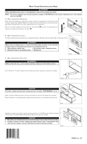
FIGURE 4-1. MINIMUM CLEARANCE BETWEEN TOP OF REAR TIRES AND
BODY STRUCTURE OVERHANG. . . . . . . . . . . . . . . . . . . . . . . 4-2
FIGURE 4-2. MINIMUM BACK OF CAB CLEARANCE . . . . . . . . . . . . . . . . . . . 4-3
FIGURE 4-3. SPACER BETWEEN FRAME SILL AND BODY RAIL -
RUBBER OR PLASTIC . . . . . . . . . . . . . . . . . . . . . . . . . . . . 4-4
FIGURE 4-4. HIGH COMPRESSION SPRING. . . . . . . . . . . . . . . . . . . . . . . . 4-4
FIGURE 4-5. RUBBER SPACER BETWEEN BRACKETS BETWEEN THE
MOUNTING BOLT AND UPPER BRACKET. . . . . . . . . . . . . . . . . . 4-4
FIGURE 4-6. CROSSMEMBER-GUSSET HOLE PATTERN
REQUIREMENTS. [INCH (MM)] . . . . . . . . . . . . . . . . . . . . . . . . 4-5
FIGURE 4-7. ACCEPTABLE U-BOLT MOUNTING WITH WOOD AND
FABRICATED SPACERS [INCH (MM)]. . . . . . . . . . . . . . . . . . . . . 4-6
FIGURE 4-8. CLEARANCE SPACE FOR AIR LINES AND CABLES . . . . . . . . . . . . 4-7
FIGURE 4-9. EXAMPLE OF FISHPLATE BRACKET AT REAR END OF BODY,
USED WITH U-BOLTS . . . . . . . . . . . . . . . . . . . . . . . . . . . . . 4-8
FIGURE 5-1. DETAIL OF FRAME EXTENSION AND JOINT WELDING . . . . . . . . . . 5-2
FIGURE 5-2. FRAME INSERT . . . . . . . . . . . . . . . . . . . . . . . . . . . . . . . . 5-3
FIGURE 5-3. COMPARISON OF ORIGINAL, SHORTENED, AND
EXTENDED WHEELBASES. . . . . . . . . . . . . . . . . . . . . . . . . . 5-4
FIGURE 5-4. CROSSMEMBER ADDED WHEN DISTANCE
EXCEEDS 60 INCHES (1524 MM) . . . . . . . . . . . . . . . . . . . . . . 5-5
FIGURE 6-1. CECU LOCATION. . . . . . . . . . . . . . . . . . . . . . . . . . . . . . . . 6-2
FIGURE 6-2. INSTRUMENT CLUSTER COMPONENTRY. . . . . . . . . . . . . . . . . . 6-3
FIGURE 6-3. CVSG GAUGES. . . . . . . . . . . . . . . . . . . . . . . . . . . . . . . . . 6-5
FIGURE 6-4. MULTIPLEXED INSTRUMENTATION BLOCK DIAGRAM . . . . . . . . . . . 6-6
FIGURE 6-5. INSTRUMENTATION HARNESS INTERFACE DIAGRAM. . . . . . . . . . . 6-7
FIGURE 6-6. FIREWALL AIR JUNCTION BLOCK . . . . . . . . . . . . . . . . . . . . . . 6-8
FIGURE 6-7. FUEL FILTER RESTRICTION PRESSURE GAUGE SENSOR
LOCATION (TYPICAL) . . . . . . . . . . . . . . . . . . . . . . . . . . . . . 6-8
FIGURE 6-8. TELLTALE SYMBOL STANDARD CARDS. . . . . . . . . . . . . . . . . . . 6-18
FIGURE 6-9. BLANK TELLTALE CARD . . . . . . . . . . . . . . . . . . . . . . . . . . . 6-18
FIGURE 6-10. TELLTALE ICONS . . . . . . . . . . . . . . . . . . . . . . . . . . . . . . . 6-19
FIGURE 6-11. SPARE BULLET CONNECTORS . . . . . . . . . . . . . . . . . . . . . . . 6-22
FIGURE 6-12. SPARE PIGTAIL CONNECTOR . . . . . . . . . . . . . . . . . . . . . . . . 6-22
FIGURE 6-13. SPARE RELAY CONNECTORS . . . . . . . . . . . . . . . . . . . . . . . . 6-23
FIGURE 7-1. CLAMP AND BUTTERFLY CLAMP . . . . . . . . . . . . . . . . . . . . . . 7-1
FIGURE 7-2. BUTTERFLY TIE . . . . . . . . . . . . . . . . . . . . . . . . . . . . . . . . 7-1
FIGURE 7-3. TIE STRAP . . . . . . . . . . . . . . . . . . . . . . . . . . . . . . . . . . . 7-1
FIGURE 7-4. HEAVY DUTY MOUNT . . . . . . . . . . . . . . . . . . . . . . . . . . . . 7-2
FIGUER 7-5. DEFINITION OF MEASUREMENTS. . . . . . . . . . . . . . . . . . . . . . 7-4
FIGURE A-1. VEHICLE IDENTIFICATION NUMBER . . . . . . . . . . . . . . . . . . . . A-3
FIGURE A-4. FRONT AXLE IDENTIFICATION. . . . . . . . . . . . . . . . . . . . . . . . A-4
FIGURE A-5. AXLE IDENTIFICATION . . . . . . . . . . . . . . . . . . . . . . . . . . . . A-5

Tables
08/06
vii
TABLE 3-1. ABBREVIATIONS USED . . . . . . . . . . . . . . . . . . . . . . . . . . 3-1
TABLE 3-2. TURNING RADIUS . . . . . . . . . . . . . . . . . . . . . . . . 3-1, 3-2
TABLE 3-3. AXLE TRACK . . . . . . . . . . . . . . . . . . . . . . . . . . 3-3
TABLE 3-4. RIDE HEIGHTS . . . . . . . . . . . . . . . . . . . . . . . . . . 3-8
TABLE 3-5. REAR SUSPENSION - REYCO 79KB . . . . . . . . . . . . . . . . . . . . . 3-10
TABLE 3-6. REAR SUSPENSION - REYCO 102 . . . . . . . . . . . . . . . . . . . . . . 3-11
TABLE 3-7. REAR SUSPENSION - NEWAY AD SINGLE . . . . . . . . . . . . . . . . . 3-12
TABLE 3-8. REAR SUSPENSION - NEWAY AD TANDEM . . . . . . . . . . . . . . . . . 3-13
TABLE 3-9. REAR SUSPENSION - HENDRICKSON PRIMAAX TANDEM . . . . . . . . . 3-14
TABLE 3-10. REAR SUSPENSION - HENDRICKSON HMX TANDEM . . . . . . . . . . . 3-15
TABLE 3-11. REAR SUSPENSION - HENDRICKSON RT TANDEM . . . . . . . . . . . . 3-16
TABLE 3-12. REAR SUSPENSION - HENDRICKSON RT TANDEM . . . . . . . . . . . . 3-17
TABLE 3-13. REAR SUSPENSION - KENWORTH AG 380 . . . . . . . . . . . . . . . . . 3-18
TABLE 3-14. REAR SUSPENSION - KENWORTH AG 400/460 . . . . . . . . . . . . . . . 3-19
TABLE 3-15. REAR SUSPENSION - KENWORTH AG 400L . . . . . . . . . . . . . . . . 3-20
TABLE 3-16. REAR SUSPENSION - KENWORTH AG460 . . . . . . . . . . . . . . . . . 3-21
TABLE 3-17. REAR SUSPENSION - CHALMERS 856-46 . . . . . . . . . . . . . . . . . . 3-22
TABLE 3-18. GROUND CLEARANCE . . . . . . . . . . . . . . . . . . . . . . . . . . 3-25
TABLE 3-19. GROUND CLEARANCE . . . . . . . . . . . . . . . . . . . . . . . . . . 3-26
TABLE 3-20. TAILPIPE STACK HEIGHT . . . . . . . . . . . . . . . . . . . . . . . . . . 3-27
TABLE 3-21. UNLADEN STACK HEIGHT . . . . . . . . . . . . . . . . . . . . . . . . . . 3-27
TABLE 3-22. FRAME LAYOUT DIMENSIONS . . . . . . . . . . . . . . . . . . . . . . . . 3-30
TABLE 3-23. VISUAL INDEX . . . . . . . . . . . . . . . . . . . . . . . . . . 3-30
TABLE 3-24. FRAME LAYOUT DIMENSIONS . . . . . . . . . . . . . . . . . . . . . . . . 3-34
TABLE 3-25. FRAME LAYOUT DIMENSIONS . . . . . . . . . . . . . . . . . . . . . . . . 3-34
TABLE 3-26. FRAME LAYOUT DIMENSIONS . . . . . . . . . . . . . . . . . . . . . . . . 3-36
TABLE 3-27. FRAME LAYOUT DIMENSIONS . . . . . . . . . . . . . . . . . . . . . . . . 3-37
TABLE 3-28. FRAME LAYOUT DIMENSIONS . . . . . . . . . . . . . . . . . . . . . . . . 3-38
TABLE 3-29. FRAME LAYOUT DIMENSIONS . . . . . . . . . . . . . . . . . . . . . . . . 3-39
TABLE 3-30. FRAME LAYOUT DIMENSIONS . . . . . . . . . . . . . . . . . . . . . . . . 3-40
TABLE 3-31. FRAME LAYOUT DIMENSIONS . . . . . . . . . . . . . . . . . . . . . . . . 3-41
TABLE 3-32. FRAME LAYOUT DIMENSIONS . . . . . . . . . . . . . . . . . . . . . . . . 3-42
TABLE 3-33. FRAME LAYOUT DIMENSIONS . . . . . . . . . . . . . . . . . . . . . . . . 3-43
TABLE 3-34. FRAME LAYOUT DIMENSIONS . . . . . . . . . . . . . . . . . . . . . . . . 3-44
TABLE 4-1. SINGLE STEEL RAILS . . . . . . . . . . . . . . . . . . . . . . . . . . 4-2
TABLE 4-2. INSERTED STEEL RAILS . . . . . . . . . . . . . . . . . . . . . . . . . . 4.2
TABLE 5-1. CUSTOMARY GRADE 8 UNF OR UNC. . . . . . . . . . . . . . . . . . . . . 5-7
TABLE 5-2. U.S. CUSTOMARY – GRADE 8. METRIC CLASS 10.9 . . . . . . . . . . . . 5-7
TABLE 6-1. TELLTALES POSITION AND COLOR . . . . . . . . . . . . . . . . . . . . . 6-20
TABLE 6-2. TSM GUIDELINE . . . . . . . . . . . . . . . . . . . . . . . . . . 6-24
TABLE 6-3. 2007 CUMMINS ISL . . . . . . . . . . . . . . . . . . . . . . . . . . 6-25
TABLE 7-1. EXHAUST - SYSTEM CLEARANCE . . . . . . . . . . . . . . . . . . . . . . 7-4
TABLE A-1. MODEL YEAR DESIGNATIONS . . . . . . . . . . . . . . . . . . . . . . . . 7-5


Section 1
Introduction
08/06
1-1
This manual was created to provide body builders with appropriate information and guidelines
useful in the body planning and installation process. This information will be helpful when installing
bodies or other associated equipment.
This manual contains appropriate dimensional information, guidelines for mounting bodies, guide-
lines for modifying frames, electrical wiring information, and other information useful in the body
installation process.
The Body Builder Manual can be very useful when specifying a vehicle, particularly when the body
builder is involved in the vehicle denition and ordering process. Early in the process, professional
body builders can often contribute valuable information that reduces the ultimate cost of the body
installation.
In the interest of continuing product development, Kenworth reserves the right to change speci-
cations or products at any time without prior notice. It is the responsibility of the user to ensure
that he is working with the latest released information. Check Kenworth.com for the latest released
version.
If you require additional information or reference materials, please contact your local Kenworth
dealer.


Section 2
Safety & Compliance
08/09
2-1
SAFETY SIGNALS
We’ve put a number of alerting messages in this book. Please read and follow them. They are there for your protection
and information. These alerting messages can help you avoid injury to yourself or others and help prevent costly
damage to the vehicle.
Key symbols and “signal words” are used to indicate what kind of message is going to follow. Pay special attention to
comments prefaced by “WARNING”, “CAUTION”, and “NOTE.” Please don’t ignore any of these alerts.
Warnings, cautions, and notes
When you see this word and symbol, the message that follows is especially vital. It signals a
potentially hazardous situation which, if not avoided, could result in death or serious injury.
This message will tell you what the hazard is, what can happen if you don’t heed the warning,
and how to avoid it.
Example: WARNING! Be sure to use a circuit breaker designed to meet liftgate amperage
Signals a potentially hazardous situation which, if not avoided, could result in minor or
moderate injury or damage to the vehicle.
Example: CAUTION: Never use a torch to make a hole in the rail. Use the appropriate drill
bit.
Provides general information: for example, the note could warn you on how to avoid damaging
your vehicle or how to drive the vehicle more efciently.
Example: Note: Be sure to provide maintenance access to the battery box and fuel tank ll
neck.
WARNING
Indicates a potentially hazardous situation which, if not avoided, could result in death or serious injury.
CAUTION
Signals a potentially hazardous situation which, if not avoided, could result in minor or moderate
injury or damage to the vehicle.
NOTE
Useful information that is related to the topic being discussed.
WARNING
CAUTION
NOTE

Section 2
Safety & Compliance
08/09
2-2
FEDERAL MOTOR VEHICLE SAFETY
STANDARDS COMPLIANCE
As an Original Equipment Manufacturer (OEM), Kenworth Truck Co. ensures that our products comply with all applicable
U.S. or Canadian Federal Motor Vehicle Safety Standards. However, the fact that this vehicle has no fth wheel and that a
Body Builder (Intermediate or Final Stage Manufacturer) will be doing additional modications means that the vehicle was
incomplete when it left the build plant. See next section and Appendix A for additional information.
An Incomplete Vehicle Document is shipped with the vehicle, certifying that the vehicle is not complete. See Figure 2–1.
In addition, afxed to the driver’s side door frame or edge is an Incomplete Vehicle Certication label. See Figure 2–2. For
further information on Vehicle Certication and Identication, see APPENDIX A “VEHICLE IDENTIFICATION.”
These documents list the U.S. or Canadian Federal Motor Vehicle Safety Standard regulations that the
vehicle complied with when it left the build plant. You should be aware that if you add, modify or alter any
of the components or systems covered by these regulations, it is your responsibility as the Intermediate
or Final Stage Manufacturer to ensure that the complete vehicle is in compliance with the particular
regulations upon completion of the modications.
FIGURE 2-1. Incomplete Ve-
hicle Certication Document
FIGURE 2-2. Locations of Certica-
tion Labels - Driver’s Door and Frame
NOTE
U.S. EPA Noise Label (U.S. registered vehicles only)
Final Stage Manufacturer
Label to be Installed by
Final Stage Manufacturer
Chassis Serial
Number
Major Components and
Weights Label
Incomplete Vehicle
Certication Label
Safety Mark (Canadian
Registry Only)
Tire, Rim and
Weight Rating
Data label
As the Intermediate or Final Stage Manufacturer, you should retain the Incomplete Vehicle Document for your records. In
addition, you should record and retain the manufacturer and serial number of the tires on the vehicle. Upon completion of
the vehicle (installation of the body and any other modications), you should afx your certication label to the vehicle as
required by Federal law. This tag identies you as the “Intermediate or Final Stage Manufacturer” and certies that the vehicle
complies with Federal Motor Vehicle Safety Standards. (See Figure 2–2.) Be advised that effective September 1, 2006, a new
regulation affects the intermediate and nal stage manufacturer certication process and documentation.
In part, if the nal stage manufacturer can complete and certify the vehicle within the instruction in the incomplete vehicle
document (IVD) the certication label would need a statement that reads, “This vehicle has been completed in accordance
with the prior manufacturers‚ IVD where applicable. This vehicle conforms to all applicable Federal Motor Vehicle Safety
Standards [and Bumper and Theft Prevention Standards if applicable] in effect in (month, year).”
However, if the vehicle can not be completed and certied with in the guidance provided in the IVD, the nal stage
manufacturer must ensure the vehicle conforms to all applicable Federal Motor Vehicle Safety Standards (FMVSS). The nal
stage manufactures certication label would need a statement that reads, “This vehicle conforms to all applicable Federal
Motor Vehicle Safety Standards [and Bumper and Theft Prevention Standards if applicable] in effect in (month, year).”

Section 2
Safety & Compliance
08/09
2-3
These statements are just part of the changes to the new certication regulation. Please refer to the February
15, 2005 nal rule for all of the details related to this regulation. You can contact NTEA Technical Services
Department at 1-800-441-NTEA for a copy of the nal rule (DocID 101760).
For Canadian nal stage manufacturers see:
http://canadagazette.gc.ca/partII/2002/20020213/html/sor55-e.html and
http://www.tc.gc.ca/acts-regulations/GENERAL/M/mvsa/regulations/mvsrg/toc_mvsrg.htm for the regulations.
Or contact:
Transport Canada
Tower C, Place de Ville, 330 Sparks Street
Ottawa, Ontario K1A 0N5
(613) 990-2309
TTY: 1-888-675-6863
Noise and Emissions Requirements
-
sions requirements for the 2007 engine.
the engine manufacturer and to obtain their approval for the revised installa-
tion. These guidelines are available from the respective local engine distribu-
DPF (the
CAUTION


Section 3
Dimensions
08/09
3-1
DIMENSIONS
This section has been designed to provide enough information to successfully layout chassis in the body planning
process. Optional equipment may not be depicted. Please contact your local Kenworth dealer if more dimensional
information is desired.
ABBREVIATIONS
Throughout this section, and in other sections as well, abbreviations are used to describe certain characteristics on your
vehicle. The chart below lists the abbreviated terms used.
TABLE 3-1. Abbreviations Used
CA BACK OF CAB TO CENTERLINE OF REAR AXLE OR CENTERLINE OF TANDEMS ON TANDEM SUSPENSION
EOF FRAME RAIL OVERHANG BEHIND REAR AXLE – MEASURED FROM THE CENTERLINE OF TANDEMS
FS FRONT SUSPENSION HEIGHT
RS REAR SUSPENSION HEIGHT
WB WHEELBASE
SOC SIDE OF CAB
BOC BACK OF CAB
TURNING RADIUS
Approximate turning radius specications are listed in the following tables as a general guide. It is important to note that
optional components may alter the results.
TABLE 3-2. Turning Radius
Model Steering Gear Front Wheel Front Tire
Rear
Suspension
Wheel Base
Est Curb to
Curb Turning
T470
Single
TAS 65
Dana Spicer
E-1202I 12K
Accuride 28487
22.5 X 8.25
Bridgestone
R287
295/75R22.5
Tandem
52” Axle
Spacing
181 28
193 29.5
201 30.5
213 32
220 33
232 34.5
240 35.5
252 37
260 38
272 39.5
280 40.5
291 42
303 43.5
323 46
331 47
TABLE 3-2 CONTINUES ON NEXT PAGE…

Section 3
Dimensions
08/09
3-2
Model Steering Gear Front Wheel Front Tire
Rear
Suspension
Wheel Base
Est Curb to
Curb Turning
T470
Dual
TAS 65
Dana Spicer
EFA-20F4 20K
Standard Track
Alcoa 82365
22.5 X 12.25
Bridgestone
M844
425/65R22.5
Tandem
52” Axle
Spacing
181 31.5
193 33.5
201 34.5
213 36.5
220 37.5
232 39
240 40
252 42
260 43
272 45
280 46
291 47.5
303 49.5
323 52.5
331 53.5
TABLE 3-2 CONTINUED

Section 3
Dimensions
08/09
3-3
Prospector Turn Circle Analysis:
Please see Figure 3-2 as an example of Kenworth’s turn circle calculation made in Prospector for your specic chassis.
Your local Kenworth dealer can provide this information to you.
FIGURE 3-1. Prospector Turn Circle Analysis
Please consult your local Kenworth Dealer for this information, as it is chassis specic.
T470
T470

Section 3
Dimensions
08/09
3-4
Wheel Tire Track
Dim ”A”
Overall Width
Dim ”B”
Dana Spicer D46-170(H)(P)
46K Dual
Alcoa 88364
22.5X8.25
BR M726EL
11R22.5
4-4 73.3” 97.8”
Dana Spicer D46-170(H)(P)
46K Dual
Alcoa 98364
24.5X8.25
BR M726EL
11R24.5
4-4 73.6” 98.0”
Dana Spicer D46-170W(H)(P)
46K Dual Wide Track
Alcoa 88364
22.5X8.25
BR M726EL
11R22.5
4-4 79.2” 103.7”
Dana Spicer D46-170W(H)(P)
46K Dual Wide Track
Alcoa 98364
24.5X8.25
BR M726EL
11R24.5
4-4 79.5” 103.9”
Dana Spicer D46-170(H)(P)
46K Dual
Alcoa 82360
22.5X12.25
BR M844F
425/65R22.5
2-4 72.7” 88.9”
Dana Spicer D46-170W(H)(P)
46K Dual Wide Track
Alcoa 82360
22.5X12.25
BR M844F
425/65R22.5
2-4 78.7” 94.9”
Wheel Tire Brake Drum
Type
Track
Dim ”A”
Overall Width
Dim ”B”
Dana Spicer E-1322I 13.2K Alcoa 98364
24.5X8.25
BR R250F
11R24.5
Cast 80.2” 91.0”
Dana Spicer E-1322W 13.2K Alcoa 98364
24.5X8.25
BR R250F
11R24.5
Cast 82.2” 93.0”
Dana Spicer D2000 20K Alcoa 82365
24.5X12.25
BR M844F
425/65R22.5
Cast 86.5” 102.7”
Dana Spicer D2000 20K Alcoa 82364
24.5X12.25
BR M844F
425/65R22.5
Cast 82.6” 98.8”
Wheel Tire Wheel
Orientation
“Track
Dim ”A”
“Overall Width
Dim ”B”
NS PSHR: WCAL ATLAS
Std Track (72.5””) 16K GAWR
Alcoa 82365
24.5X12.25
BR M844F
425/65R22.5
Default-
Same as RR
79.4” 95.6”
NS PSHR: WCAL ATLAS
Wide Track (77.5””)
“Alcoa 82365
24.5X12.25
BR M844F
425/65R22.5
Option
Same as FR
71.1” 87.3”
TABLE 3-3. Axle Track
AXLE TRACK AND TIRE WIDTH
The dimensions provided in this section are representative of some typical product combinations. The purpose of this section is •
to demonstrate some of the typical dimensions.
Axle Track: The distance between the dual tire centerlines on a dual tire arrangement or the distance between the tire centerlines •
on a single tire arrangement.
Width: The distance over the outermost tire sidewall to sidewall.•
These dimensions may be signicant to the following:
Appearance relative to other tires and chassis mounted equipment.•
Load carrying capacity. Different wheel disc offset can have a positive or negative impact on the axle carrying capacity of the •
axle.

Section 3
Dimensions
08/09
3-5
OVERALL DIMENSIONS
This section includes drawings and charts. The Extended Day Cab is also included.
On the pages that follow, detail drawings show particular views of each vehicle, all dimensions are in inches (in). They
illustrate important measurements critical to designing bodies of all types. See the “Contents” at the beginning of the
manual to locate the drawing that you need.
Note: To determine overall height please locate the chart Table 3-4 on page 3-8 and 3-9 and add that value to the height.
All heights are given from the bottom of the frame rail.
Kenworth also offers .dxf les and frame layouts of ordered chassis four weeks prior to build. Please speak with your
salesman to request this feature when specifying your chassis.
The following drawings are shown with standard chassis components and the T470 xed grille hood.

Section 3
Dimensions
08/09
3-6
T470 FIXED GRILLE HOOD WITH EXTENDED FRONT FRAME
The following drawings are of a T470 xed grille hood with the optional extended front frame. These extended frame rails
can be used with or without FEPTO adapters.
/