Page is loading ...

© SPX Corporation
Sheet No.
Issue Date: Rev. C, 1-15-03
Parts List &
Operating Instructions
for: 1896
Form No. 102725
1 of 8
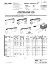
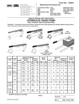
Oil Filter Crusher
Max. Capacity: 25 Tons
SPX Corporation
655 Eisenhower Drive
Owatonna, MN 55060-0995 USA
Phone: (507) 455-7000
Tech. Serv.: (800) 533-6127
Fax: (800) 955-8329
Order Entry: (800) 533-6127
Fax: (800) 283-8665
International Sales: (507) 455-7223
Fax: (507) 455-7063

Parts List & Operating Instructions
Refer to any operating instructions included with the product for detailed
information about operation, testing, disassembly, reassembly, and
preventive maintenance.
Items found in this parts list have been carefully tested and selected by
OTC. Therefore: Use only OTC replacement parts!
Additional questions can be directed to the OTC Technical Services
Department.
Form No. 102725, Sheet 1 of 8, Back
Item
No. Part
No. No.
Req'd Description
153815 1Right Stand Assembly
2214480 8Hex Hd. Cap Screw (5/16-18 x 3-3/4" Lg.)
313116 8 Locknut (5/16-18)
453814-BK2 1Plate
553817-BL2 1Cover
6219390 1Decal
7219389 1Decal
862494 1Decal
9219005 1Handle
10 48976-BL2 1Door
11 48977-BK2 1Grate
12 53818-BL2 1Drain Pan
13 53816 1Left Stand Assembly
14 219004 4Leveling Screw
15 311709 1Angle

© SPX Corporation
Sheet No.
Issue Date: Rev. C, 1-15-03
Parts List & Operating Instructions Form No. 102725
2 of 8
Oil Filter Crusher
Side View

Parts List & Operating Instructions
Item
No. Part
No. No.
Req'd Description
110215 8Hex Nut (3/4-16)
253804 1Bottom Plate
310177 12 Rd. Hd. Machine Screw (1/4-20 x 5/8" Lg.)
410245 12 Lockwasher (for 1/4" bolt)
5311676 4Rod
611856 2Rd. Hd. Machine Screw (10-24 x 1" Lg.)
710197 2Hex Nut (10-24)
810241 2 Lockwasher (#10)
914812 8 Pan Hd. Tapping Screw (8-18 x 3/8" Lg.)
10 219282 2Roller Latch
11 211646 1Tee Fitting
12 10673 1 Straight Fitting (3/8 to 3/8)
13 53882 1Cylinder Assembly
14 15467 4 Rd. Hd. Screw (10-24 x 5/16" Lg.)
15 10676 2 Straight Fitting (3/8 to 1/4)
16 218761 1Tee Fitting
17 311730 1Hydraulic Hose (3/8 I.D. x 50" Lg.)
18 311731 1Hydraulic Hose (3/8 I.D. x 70" Lg.)
19 62489 1Electrical Control Box Assembly
20 48975-BK2 1Cover
21 200188 1Warning Decal
22 219215 4Special Washer
23 10032 4Hex Hd. Cap Screw (5/16-18 x 1" Lg.)
24 10230 8Plain Washer (for 5/16" bolt)
25 13116 8 Locknut (5/16-18)
26 11203 2Straight Conduit Connector
27 48954 1Electric Motor/Hydraulic Pump Assembly
28 10080 4Hex Hd. Cap Screw (1/2-13 x 1-1/4" Lg.)
29 10249 4 Lockwasher (for 1/2" bolt)
30 12004 2Plain Washer (for 1/2" bolt)
31 11108 4Ext. Tooth Lockwasher (#10)
32 215749 4Hex Head Cap Screw
33 219005 1Handle
Form No. 102725, Sheet 2 of 8, Back

© SPX Corporation
Sheet No.
Issue Date: Rev. C, 1-15-03
Parts List & Operating Instructions Form No. 102725
3 of 8
Ground Connections
Control Box Assembly

Parts List & Operating Instructions
Item
No. Part
No. No.
Req'd Description
1218630 1 Pressure Switch (3000 PSI)
2218618 1 Pressure Switch (1000 PSI)
3219358 1Grommet
439692 1 Transformer
5205189 1Grounding Decal
615993 1Strain Relief Bushing
811203 1Straight Conduit Connector
9311370 1Cord Set (110 volt)
10 218831 1Strain Relief Bushing
11 312277 12-Pole Contactor
12 15467 6 Screw (10-24 x 5/16" Lg.)
13 206509 4Pan Hd. Tapping Screw (6-20)
14 39092 2General Purpose Relay
15 62488-BK2 1Mounting Plate
16 218608 1Plunger Switch
17 218607 1Contact Block (NC)
18 311710-BK2 1Switch Plate
19 218605 1Pushbutton Switch (Stop)
20 219281 1Pushbutton Switch (Retract)
21 218606 2Contact Block (NO)
22 218604 1Pushbutton Switch (Start)
23 208812 .6 ft. Channel Trim (Grommet)
24 10199 3Hex Nut (1/4-20)
25 11351 3Ext. Tooth Lockwasher
26 15535 1Hex Hd. Cap Screw (1/4-20 x 1-1/2" Lg.)
28 11108 6Ext. Tooth Lockwasher (#10)
219356 1 Fuse (shown on Sheet 4)
Form No. 102725, Sheet 3 of 8, Back
Conductors North American International
Line Black Brown
Neutral White Blue
Ground Green Green/Yellow
North American & International Color Codes
Warning: To help prevent personal injury, any
repair work or troubleshooting must be performed
by qualified personnel who are familiar with this
equipment. Electrical work must be performed by a
qualified electrician.

© SPX Corporation
Sheet No.
Issue Date: Rev. C, 1-15-03
Parts List & Operating Instructions Form No. 102725
4 of 8
Electrical Assembly

Parts List & Operating Instructions Form No. 102725, Sheet 4 of 8, Back
Wiring Schematic
5A FUSE
1

© SPX Corporation
Sheet No.
Issue Date: Rev. C, 1-15-03
Parts List & Operating Instructions Form No. 102725
Cylinder Assembly
5 of 8

Parts List & Operating Instructions Form No. 102725, Sheet 5 of 8, Back
Item
No. Part
No. No.
Req'd Description
110027 2Cap Screw (5/16-18 x 5/8" Lg.)
2219192 2Plain Wide Washer
310295 1O-ring Packing
462542 1Cylinder Weldment
5218616 1Rod Seal
6219958 2Socket Hd. Set Screw
7219234 1Stamp
8218724 1Rod Wiper
9311677 1Threaded Adapter
10 218615 1Rod Wear Ring
11 311679 1Cylinder Rod
12 503122 1Piston
13 218614 1Piston Wear Ring
14 10858 1O-ring Packing
15 19171 1O-ring Back-up Washer
16 503216 1Piston with Loading Ring Seal
17 311675 1Retaining Ring
18 12916 1Socket Hd. Cap Screw
19 49162 1Cylinder Cap

© SPX Corporation
Sheet No.
Issue Date: Rev. C, 1-15-03
Parts List & Operating Instructions Form No. 102725
Pump & Motor Assembly
6 of 8

Parts List & Operating Instructions Form No. 102725, Sheet 6 of 8, Back
Item
No. Part
No. No.
Req'd Description
1311666-21 1AC Motor (230 Volt, 2 HP)
2311665-2 4 Bolt (1/4-20 x 3/4" Lg.)
3311665-3 1Motor Adapter
4311665-4 1O-ring
5311665-5 1Shaft Seal
6311666-22 1Pump Assembly
7311666-23 1Unload Assembly
8311665-8 1Suction Cover Assembly
9311666-27 1Plumbing Assembly Inlet
10 311665-6 1Reservoir (Steel) Early Models
223520 1Reservoir (Plastic) Late Models
11 311665-1 1Coupling
12 311768-1 1Solenoid Valve
13 311768-4 1Spring & Ball
14 311665-17 1Spring Retainer
15 311768-3 1End Head
16 311665-20 1Check Valve Assembly
17 311665-14 1Spring
18 311768-2 1D03 N2 Assembly Kit
19 311665-13 1Relief Cap
20 311665-12 1Adjusting Screw
21 10378 1Ball
22 311665-7 2Taptite Screw (M6-10 x 12mm)
23 311665-9 1 Washer (.338 x .625 x .060 Lg.)
24 311665-10 1 Torx Bolt (5/16-18 x 1" Lg.)
25 311665-11 1Breather Cap
26 311666-24 1Pump Assembly
27 311666-25 2 Washer (.330 x .525 x .055 thk.)
28 311666-26 2Threaded Rod (5/16-24 x 8" Lg.)
Hydraulic
Schematic

© SPX Corporation
Sheet No.
Issue Date: Rev. C, 1-15-03
Parts List & Operating Instructions Form No. 102725
Safety Precautions
7 of 8
Caution: To help prevent personal injury and/or equipment damage,
•Read and carefully follow these instructions. Most problems with new equipment are caused by incorrect
installation or operation.
•Wear eye protection that meets ANSI Z87.1 and OSHA requirements.
•Keep tie rod nuts torqued at 300-320 ft. lbs.
•Remove the crushed filter carefully. Sharp edges can scratch, cut, or puncture skin.
Hydraulic
•If a hydraulic hose ruptures, bursts, or needs to be disconnected, immediately shut the pump OFF. Never
grasp a leaking, pressurized hose with your hands, because the force of escaping hydraulic fluid could cause
serious injury. Regularly inspect hoses for signs of wear or stress, and replace if needed.
•Do not exceed the hydraulic pressure rating (3500 PSI) noted on the pump's nameplate. Do not tamper with
the internal relief valve; creating pressure beyond the rated capacity of this unit can result in personal injury.
•Completely retract the cylinder before adding oil to the pump reservoir. Overfilling the pump reservoir can
cause personal injury due to excess pressure created in the reservoir when the cylinder is retracted.
Electric
•Electrical work must be performed by a qualified electrician.
•The crusher is designed for intermittent use only; continuous usage can cause the pump motor to overheat.
If motor temperature exceeds 150° F, let the unit cool down before starting it again.
•Do not use an extension cord with this unit.
•The pump must be connected to a single phase, 60 cycle, 230 volt power source with a minimum 20 amp rating.
•If the circuit breaker or fuse opens continuously, locate the problem and correct it. Do not increase power line
capacity by replacing the fuse with another of higher value, because this could overheat the power line and
possibly cause a fire.
•Avoid conditions that create an electrical hazard. If the power cord is damaged or the wiring exposed, replace
or repair the power cord immediately.
•Disconnect the power supply before removing the motor control box cover or before performing repairs or
maintenance.
•Keep the override switch clean and in working order.
1. Refer to the following color code chart, and install a 230 volt male power plug on the end of the cord set.
Setup Instructions
Conductors North American International
Line Black Brown
Neutral White Blue
Ground Green Green/Yellow
North American & International Color Codes
2. Install four leveling screws (Item #14, Sheet 1) on bottom of stand angle supports.
3. Connect the pump motor to a power source (single phase, 60 cycle, 230 volt, minimum 20 amp rating).
4. Cycle the pump and cylinder without building pressure. Retract the cylinder and check the oil level in the pump
reservoir. Note: If the cylinder does not advance, refer to the procedure for "Bleeding Air from the System."

Parts List & Operating Instructions Form No. 102725, Sheet 7 of 8, Back
1. Place an approved waste oil container under the drain fitting in the
drain pan.
2. Lift the sliding door and place the oil filter on the plate, centering it
between the tie rods. The filter's open end (the sealing area
containing the o-ring) must be facing down toward the drain holes.
When the oil filter is crushed, the oil will be forced into the holes.
3. Close the sliding door and press the START button. The pump will
extend the ram, retract the ram, and automatically shut off when the
cycle is complete. If it is necessary to interrupt the cycle, press
the STOP button.
4. Open the sliding door and remove the crushed filter, being careful
not to scratch, cut, or puncture your skin on the filter's sharp edges.
Do not open the sliding door while the ram is extending.
Note: When crushing the smaller automotive size filters, cycle
time can be reduced by stopping the ram during the return stroke:
A. Press the STOP button or open the sliding door.
B. Press the RETRACT button to reverse the cylinder just
enough to remove the crushed filter and insert the next
filter.
5. Recycle or dispose of waste oil and oil filters according to local,
state, and federal regulations.
Operating Instructions
Maintenance
1. Dirt is the greatest single cause of failure in hydraulic systems. Keep the outer surface of the pump, including hose
connections and the filler cap, as clean as possible.
2. Keep the breather hole in the filler cap clean and unobstructed.
3. Keep the override switch clean and in working order.
Changing the Oil in the Pump Reservoir
The oil should be changed every 5000 cycles (or about once each year) depending upon the degree of usage and the
cleanliness of the work environment.
1. Release system pressure.
2. Place a bucket under the pump reservoir. Loosen the plug on the bottom of the reservoir, and let the oil drain out.
Tighten the drain plug.
3. Remove dirt from the area around the filler cap. Any abrasive materials collected in the oil will damage the polished
surfaces and precision-fit components of this pump.
4. Remove the filler cap, and insert a clean funnel (with a filter) into the fill port.
5. Verify that the cylinder is completely retracted. Add SAE 10W or 20W hydraulic oil (OTC #9036, 9037, or equivalent)
until the oil level is one inch from the bottom of the fill port.
6. Cycle the pump and cylinder without building pressure. Retract the cylinder and check the oil level in the pump
reservoir. Note: If the cylinder does not advance, refer to the procedure for "Bleeding Air from the System."
Bleeding Air from the System
If the cylinder responds slowly or in an unstable ("spongy") manner, air is trapped in the hydraulic system. To remove the
air, loosen the hose fitting at the top of the ram. Run the pump until you see a steady flow of oil (free of air bubbles). Tighten
the fitting.
Stop
Button Retract
Button
Start
Button
Sliding
Door
Drain
Pan
Pump
Reservoir

© SPX Corporation
Sheet No.
Issue Date: Rev. C, 1-15-03
Parts List & Operating Instructions Form No. 102725
Warning: To help prevent personal injury, any repair work or troubleshooting must be performed
by qualified personnel who are familiar with this equipment. Electrical work must be performed by a
qualified electrician. Use the correct gauges and equipment when trouble-shooting.
North American & International Color Codes
Conductors North American International
Line Black Brown
Neutral White Blue
Ground Green Green/Yellow
Problem Cause Solution
Motor does not start 1. Unit is not plugged in
1. Make power connections
2. No voltage supply
2. Check line voltage
3. Broken lead wire or defective
3. Replace defective parts
power cord plug
4. Defective switches
4. Replace defective parts
5. Defective starter relay
5. Replace defective parts
6. Circuit breaker tripped because
6. Add or use a circuit with correct
total amp draw is too high for circuit
amperage
7. Overheated motor
7. Wait for motor to cool
8. Defective motor
8. Replace or repair motor
9. Defective override switch
9. Repair or replace override switch
10. Blown fuse
10. Replace 5 amp fuse (#219356)
11. Sliding door not actuating override
11. Slightly adjust tab on corner of
switch when door is closed
sliding door until it contacts
override switch
Pump is not delivering oil or 1. Oil level is too low
1. Retract cylinder. Fill reservoir to
delivers only enough oil to
within 1" of bottom of fill port.
advance cylinder partially or 2. Air in the system
2. Bleed the system
erratically. 3. Air leak in suction line
3. Tighten suction line
4. Dirt in pump or filter is plugged
4. Clean pump filter
5. Cold oil or oil is too heavy
5. Change to a lighter weight oil
(oil viscosity is too high)
6. Motor rotating in wrong direction
6. Check electric schematic on motor
7. Vacuum in reservoir
7. Check breather hole in filler plug
for obstruction
8. Worn pressure pump
8. Replace pump
Pump will not build full pressure 1. External leakage
1. Look for leaks at cylinder, hose, or
power unit. Seal leaking pipe
fittings with pipe sealant.
2. Worn pressure pump
2. Replace pump
3. Pressure switch not set correctly
3. Replace pressure switch or send
unit to authorized service center
for repair
8 of 8
Troubleshooting
/