Page is loading ...

Installation Instructions
SurShield
SurShield
Guardrail Clamping System
®

WARNING
WARNING
THIS DEVICE SHOULD ONLY BE USED UNDER THE CLOSE
SUPERVISION OF AN OSHA CERTIFIED COMPETENT PERSON.
The SurShield
®
Guardrail Clamp has been tested and certified
by an independent national engineering testing firm
as exceeding all applicable United States Federal OSHA
temporary guardrail regulations .
THIS DEVICE IS NOT DESIGNED FOR USE
AS AN ANCHORAGE TIE-OFF POINT.
FAILURE TO OBSERVE MANUFACTURERS INSTRUCTIONS
MAY RESULT IN SERIOUS OR FATAL INJURY.
MANUFACTURER CERTIFIES
CONFORMANCE TO
OSHA
REQUIREMENTS
DO NOT OVER-TIGHTEN THE CENTRAL TENSION BOLT!
Installer MUST follow proper fall protection procedures during installation!
PINCH POINTS CAN
CAUSE PERSONAL INJURY
OSHA's Regulations (Standards - 29 CFR) Guardrail Systems - Non-Mandatory Guidelines for Complying with 1926.502(b) - 1926 Subpart M App B - States in part:
The standard requires guardrail systems and components to be designed and built to meet the requirements of 1926.502(b)(3), (4), and (5). This Appendix serves
as a non-mandatory guideline to assist employers in complying with these requirements . . .
(1) For wood railings: Wood components shall be minimum 1500 lb-ft/in(2) fiber (stress grade) construction grade lumber; the posts shall be at least 2-inch by
4-inch (5 cm x 10 cm) lumber spaced not more than 8 feet (2.4 m) apart on centers; the top rail shall be at least 2-inch by 4-inch (5 cm x 10 cm) lumber, the
intermediate rail shall be at least 1-inch by 6-inch (2.5 cm x 15 cm) lumber. All lumber dimensions are nominal sizes as provided by the American Softwood Lumber
Standards, dated January 1970 . . .

STEP ONE
SurShield
®
Guardrail Clamping System
Installation Procedures for
Guardrail Applications
ASSEMBLE CLAMP AND POST
If necessary, mount the Safety Boot
®
to the clamp base
using supplied fender washers and fastening nuts. Cut 2
- 2X4 studs using construction grade (stress grade)
lumber to 42 inch lengths and fasten together using 2-
inch long deck screws or framing nails to create a double
2X4 post. Insert the post into the center core of the
Safety Boot and secure with a X 2- inch lag screw and
washer through the provided hole in the side wall (See
Figure 1).
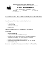
STEP TWO
PLACEMENT OF POSTS
Measure the distance between the post/clamps. Federal
OSHA recommends that the maximum distance between
posts should not exceed 8 feet on centers using construc-
tion grade (stress grade) lumber for guardrail systems.
Loosen the central tension bolt, disengage the locking
mechanism and slide up the stanchion. Flip the ring back
and under the locking mechanism to hold it in place
(See Figure 2).
While holding the stanchion firmly, grab the SurShield
from the back where it says “LIFT HERE” and raise
the main body to extend the bottom jaw section until
fully open.
Figure 2
Figure 1

STEP THREE
With the jaw fully extended, swing the
SurShield over the edge of the structure
and rest the base on the surface (See
Figure 3).
Unhook the locking mechanism from the
ring and slide down onto the top plate, lift
stanchion using the lift ring and place
locking mechanism into corresponding
hole depending on the thickness of the
structure (See Figure 4).
Tighten the central tension bolt while
lifting the stanchion with the ring until the
unit is snug.
Securely tighten the central tension bolt
using a 15/16 inch wrench or socket
(See Figure 5).
INSTALL CLAMP AND POST ONTO THE EDGE OF THE STRUCTURE
Figure 3
DO NOT OVER TIGHTEN THE
CENTRAL TENSION BOLT!
Figure 4
Figure 5

STEP FOUR
For mid rail placement, measure from the top of the
walking/working surface up to a height of 21 inches and
mark the post.
Federal OSHA Standard 1926.502(b)(2)(i) states:
Midrails, when used, shall be installed at a height
midway between the top edge of the guardrail system
and the walking/working level (See Figure 6).
For top rail placement, attach the top rail flush with the
top of the 42 inch post.
Federal OSHA Standard 1926.502(b)(1) states:
Top edge height of top rails, or equivalent guardrail
system members, shall be 42 inches (1.1 m) plus or
minus 3 inches (8 cm) above the walking/working level.
When conditions warrant, the height of the top edge may
exceed the 45-inch height, provided the guardrail
system meets all other criteria of this paragraph (See
Figure 7).
Measure and cut 2X4’s to fit into the slots on each Safety
Boot
®
for simple OSHA required toeboard protection
(See Figure 8).
ATTACH MID RAILS AND TOP RAILS TO POSTS
Figure 8
Figure 7
Figure 6

OSHA Regulations (Standards - 29 CFR)
Fall protection systems criteria and practices. - 1926.502
1926.502(b)
"Guardrail systems." Guardrail systems and their use shall comply with
the following provisions:
1926.502(b)(1)
Top edge height of top rails, or equivalent guardrail system members,
shall be 42 inches (1.1 m) plus or minus 3 inches (8 cm) above the
walking/working level. When conditions warrant, the height of the top
edge may exceed the 45-inch height, provided the guardrail system
meets all other criteria of this paragraph.
Note: When employees are using stilts, the top edge height of the top
rail, or equivalent member, shall be increased an amount equal to the
height of the stilts.
1926.502(b)(2)
Midrails, screens, mesh, intermediate vertical members, or equivalent
intermediate structural members shall be installed between the top
edge of the guardrail system and the walking/working surface when
there is no wall or parapet wall at least 21 inches (53 cm) high.
1926.502(b)(2)(i)
Midrails, when used, shall be installed at a height midway between the
top edge of the guardrail system and the walking/working level.
1926.502(b)(2)(ii)
Screens and mesh, when used, shall extend from the top rail to the
walking/working level and along the entire opening between top rail
supports.
1926.502(b)(2)(iii)
Intermediate members (such as balusters), when used between
posts, shall be not more than 19 inches (48 cm) apart.
1926.502(b)(2)(iv)
Other structural members (such as additional midrails and architec-
tural panels) shall be installed such that there are no openings in the
guardrail system that are more than 19 inches (.5 m) wide.
1926.502(b)(3)
Guardrail systems shall be capable of withstanding, without failure, a
force of at least 200 pounds (890 N) applied within 2 inches (5.1 cm)
of the top edge, in any outward or downward direction, at any point
along the top edge.
1926.502(b)(4)
When the 200 pound (890 N) test load specified in paragraph (b)(3)
of this section is applied in a downward direction, the top edge of the
guardrail shall not deflect to a height less than 39 inches (1.0 m)
above the walking/working level. Guardrail system components select-
ed and constructed in accordance with the Appendix B to subpart M
of this part will be deemed to meet this requirement.
1926.502(b)(5)
Midrails, screens, mesh, intermediate vertical members, solid panels,
and equivalent structural members shall be capable of withstanding,
without failure, a force of at least 150 pounds (666 N) applied in any
downward or outward direction at any point along the midrail or other
member.
1926.502(b)(6)
Guardrail systems shall be so surfaced as to prevent injury to an
employee from punctures or lacerations, and to prevent snagging of
clothing.
1926.502(b)(7)
The ends of all top rails and midrails shall not overhang the terminal
posts, except where such overhang does not constitute a projection
hazard.
1926.502(b)(8)
Steel banding and plastic banding shall not be used as top rails or
midrails.
1926.502(b)(9)
Top rails and midrails shall be at least one-quarter inch (0.6 cm)
nominal diameter or thickness to prevent cuts and lacerations. If wire
rope is used for top rails, it shall be flagged at not more than 6-foot
intervals with high-visibility material.
1926.502(b)(10)
When guardrail systems are used at hoisting areas, a chain, gate or
removable guardrail section shall be placed across the access open-
ing between guardrail sections when hoisting operations are not
taking place.
1926.502(b)(11)
When guardrail systems are used at holes, they shall be erected on all
unprotected sides or edges of the hole.
1926.502(b)(12)
When guardrail systems are used around holes used for the passage
of materials, the hole shall have not more than two sides provided with
removable guardrail sections to allow the passage of materials. When
the hole is not in use, it shall be closed over with a cover, or a guardrail
system shall be provided along all unprotected sides or edges.
1926.502(b)(13)
When guardrail systems are used around holes which are used as
points of access (such as ladderways), they shall be provided with a
gate, or be so offset that a person cannot walk directly into the hole.
1926.502(b)(14)
Guardrail systems used on ramps and runways shall be erected along
each unprotected side or edge.
1926.502(b)(15)
Manila, plastic or synthetic rope being used for top rails or midrails
shall be inspected as frequently as necessary to ensure that it contin-
ues to meet the strength requirements of paragraph (b)(3) of this
section.

ENGINEERING REPORT SUMMARY

MANUFACTURER CERTIFIES
CONFORMANCE TO
OSHA
REQUIREMENTS
Be sure and visit our website at www.safetyboot.com
for information on our other guardrail products:
Toll Free: 800.804.4741
Local: 832.593.0400
www.safetyboot.com
VersiShield
VersiShield
Guardrail Clamping System
®
U.S. Patent No. 7234689
U.S. Patent No. 7284746
U.S. Patent No. 7530551
U.S. and Foreign Patents Pending
©2016 Safety Maker, Inc.
Safety Maker Inc.
P.O. Box 880
Cypress, Texas 77410-0880
IMPORTANT NOTE:
ALWAYS wear the proper
fall protection
when installing this product.
/