Page is loading ...

IOM-WQ-PWRO440
Table of Contents
I. Introduction
A. Specifications
B. RO Overview
C. Pre-treatment
II. Controls, Indicators, and Components
III. Operation
A. Installation
B. Plumbing Connections
C. Electrical
D. Startup
E. Control Function
F. Operation and Maintenance Log
G. Troubleshooting
IV. Replacement Parts List
V. Membrane Replacement
VI. Appendix
Temperature Correction Factors
PWRO4401
Installation, Operation
and Maintenance Manual
Reverse Osmosis System
Series PWRO440
Important
Please read the entire manual before proceeding with the
installation and startup:
• Do not use where the water is microbiologically unsafe.
• Always turn off the unit, shut off the feed water, and disconnect
the electrical power when working on the unit.
• Never allow the pump to run dry.
• Never start the pump with the reject valve closed.
• Never allow the unit to freeze or operate with a feed water
temperature above 100°F (38°C).
Notes
Changes in operating variables are beyond the control of Watts. The
end user is responsible for the safe operation of this equipment.
The suitability of the product water for any specific application is the
responsibility of the end user.
Successful long-term performance of an RO system depends on
proper operation and maintenance of the system. This includes
the initial system startup and operational startups and shutdowns.
Prevention of fouling or scaling of the membranes is not only a
matter of system design, but also a matter of proper operation.
Record keeping and data normalization are required in order to know
the actual system performance and to enable corrective measures
when necessary. Complete and accurate records are also required in
case of a system performance warranty claim.
Changes in the operating parameters of an RO system can be
caused by changes in the feed water or can be a sign of trouble.
Maintaining an operation and maintenance log is crucial in
diagnosing and preventing system problems. For your reference,
a typical log sheet is included in this manual.
PURE WATER
Note: Do not use with water that is microbiologically unsafe or
of unknown quality without adequate disinfection before or after
the system.

C. Pretreatment
The RO feed water must be pretreated in order to prevent mem-
brane damage and/or fouling. Proper pretreatment is essential for
reliable operation of any RO system.
Pretreatment requirements vary depending on the nature of the feed
water. Pretreatment equipment is sold separately. The most common
forms of pretreatment are described below.
Media Filter - Used to remove large suspended solids (sediment)
from the feed water. Backwashing the media removes the trapped
particles. Backwash can be initiated by time or differential pressure.
Water Softener - Used to remove calcium and magnesium from
the feed water in order to prevent hardness scaling. The potential
for hardness scaling is predicted by the Langelier Saturation Index
(LSI). The LSI should be zero or negative throughout the unit unless
approved antiscalents are used. Softening is the preferred method of
controlling hardness scale.
Carbon Filter - Used to remove chlorine and organics from the
feed water. Free chlorine will cause rapid irreversible damage to the
membranes.
The residual free chlorine present in most municipal water
supplies will damage the thin film composite structure of the
membranes used in this unit. Carbon filtration or sodium
bisulfite injection should be used to completely remove the
free chlorine residual.
Chemical Injection - Typically used to feed antiscalant, coagulant,
or bisulfite into the feed water or to adjust the feed water pH.
Prefilter Cartridge - Used to remove smaller suspended solids and
trap any particles that may be generated by the other pretreatment.
The cartridge(s) should be replaced when the pressure drop across
the housing increases 5 - 10 psig over the clean cartridge pressure
drop. The effect of suspended solids is measured by the silt density
index (SDI) test. An SDI of five (5) or less is specified by most
membrane manufacturers and three (3) or less is recommended.
Iron & Manganese - These foulants should be removed to less
than 0.1 ppm. Special media filters and/or chemical treatment is
commonly used.
pH - The pH is often lowered to reduce the scaling potential. If the
feed water has zero hardness, the pH can be raised to eliminate
CO2.
Silica: Reported on the analysis as SiO2. Silica forms a coating on
membrane surfaces when the concentration exceeds its solubility.
Additionally, the solubility is highly pH and temperature dependent.
Silica fouling can be prevented with chemical injection and/or
reduction in recovery.
2
I. Introduction
The separation of dissolved solids and water using RO membranes
is a pressure driven temperature dependent process. The membrane
material is designed to be as permeable to water as possible, while
maintaining the ability to reject dissolved solids.
The main system design parameters require the following:
• Internal flows across the membrane surface must be high enough
to prevent settling of fine suspended solids on the membrane
surface.
• The concentration of each dissolved ionic species must not exceed
the limits of solubility anywhere in the system.
• Pre-treatment must be sufficient to eliminate chemicals that would
attack the membrane materials.
PWRO4401 PWRO4402 PWRO4403
Maximum Productivity
(gallons per day)
2200 4400 6600
Quality (average membrane
rejection)
98 %
Recovery (user adjustable) 15 - 75 % 25 – 75% 32 - 75 %
Membrane Size 4" x 40"
Number Of Membranes 1 2 3
Prefilter (system ships with
one 5 micron cartridge)
20"
Feed Water Connection 3/4" NPTF
Product Water Connection
(tubing OD)
5/8"
Reject Water Connection
(tubing OD)
5/8"
Feed Water Required
(maximum)
10 gpm 12 gpm 14 gpm
Feed Water Pressure
(minimum)
10psi
Drain Required (maximum) 10 gpm 12 gpm 14 gpm
Electrical Requirement 230V 10 amps 230V 12 amps 230V 15 amps
Motor Horse Power 3/4 1 1 1/2
Dimensions W x D x H
(approximate inches)
20 x 20 x 50 20 x 26 x 50
Shipping Weight (estimated
pounds)
120 150 180
A. Specifications
RO Membrane
Feed Water Product Water
Reject Water
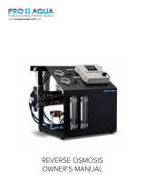
B. RO Overview
Reverse osmosis systems utilize semipermeable membrane ele-
ments to separate the feed water into two streams. The pressurized
feed water is separated into purified (product) water and concentrate
(reject) water. The impurities contained in the feed water are carried
to the drain by the reject water. It is critical to maintain adequate
reject flow in order to prevent membrane scaling and/or fouling.
Notes:
• Maximum production based on a feed water of 77°F, SDI < 1, 1000 ppm TDS, and pH 7.
Individual membrane productivity may vary (± 15%). May be operated on other feed waters
with reduced capacity.
• Percent rejection is based on membrane manufacturer’s specifications; overall system
percent rejection may be less.

II. Controls, Indicators, and
Components
(See Figure 1)
A On / Off Switch – Turns the unit on and off.
B Low-pressure indicator – Turns on when low pump inlet
pressure is detected.
C Tank full / Interlock indicator – Turns on when the unit is shut
down due to high tank or pretreatment interlock.
D Reject Control Valve – Controls the amount of reject flow.
E Reject Recycle Control Valve – Controls the amount of recycle
flow.
F Prefilter Outlet Pressure Gauge – Indicate the outlet pressures of
the prefilter.
G Pump Discharge Pressure Gauge – Indicates the membrane
feed pressure.
H Reject Flow Meter – Indicates the reject flow rate in gallons per
minute (gpm).
I Product Flow Meter – Indicates the product flow rate in gallons
per minute (gpm).
J Prefilter Housing – Contains the RO prefilter.
K RO Feed Pump – Pressurizes the RO feed water.
L RO Membrane Housing(s) – Contains the RO membrane(s).
M Water Quality Meter – Indicates the quality of the feed and
product water in parts per million of total dissolved solids
(PPM – TDS).
N Feed Water Inlet.
III. Operation
A. Installation
1. Proper pretreatment must be determined and installed prior to
the RO system.
2. The water supply and pretreatment equipment should be
sufficient to provide a minimum of 10-psig at the maximum
feed flow.
3. An electrical disconnect switch located within 10 feet of the unit
is recommended.
4. Responsibility for meeting local electrical and plumbing codes
lies with the owner / operator.
5. Install indoors in an area protected from freezing and direct
sunlight. Space allowances for the removal of the membranes
from the pressure vessels should be provided.
6. Verify that a prefilter cartridge is installed in the housing.
(see Figure #1, Item J).
B. Plumbing Connections
Note: It is the responsibility of the end user to ensure that the
installation is done according to local codes and regulations.
1. Connect the pretreated feed water line to the prefilter inlet
(Figure # 1 Item N). A feed water shutoff valve should be located
within 10 feet of the system.
2. Temporarily connect the product water outlet to a drain. The
product outlet is located behind the panel at the top of the
product flow meter. The product water line should never be
restricted. Membrane and/or system damage may occur if the
product line is blocked.
3. Connect the reject water outlet to a drain. The reject outlet is
located behind the panel at the top of the reject flow meter. The
reject drain line should never be restricted. Membrane and/or
system damage may occur if the reject drain line is blocked. An
air gap must be located between the end of the drain line and
the drain. The use of a standpipe or other open drain satisfies
most state and local codes and allows for visual inspection and
sampling.
3
Figure 1

4
C. Electrical
Note: It is the responsibility of the end user to ensure that the
installation is done according to local codes and regulations.
1. Make sure the on / off switch is in the off position (Figure #1
item A).
2. Wire the common side of the motor starter to the incoming
power.
3. Connect the incoming power supply to the contactor terminals
as shown.
4. For Tank Level Switch you will need to cut off the plug and wire
the float switch to the tank level input on the controller when us-
ing this float switch with a Watts commercial RO system. Note:
You will need to remove the factory installed jumper wire from
the tank level terminals connectors 5 & 6 in the controller. See
RO system manual for more details.
D. Startup
1. Verify that the pretreatment equipment is installed and working
properly. Verify that no free chlorine is present in the feed water.
2. Verify that the on / off switch is in the off position.
3. Verify that a filter cartridge is installed in the prefilter housing.
4. Open the reject control valve completely (Figure # 1 item D) by
turning it counterclockwise.
5. Close the reject recycle control valve (Figure # 1 item E)
completely by turning it clockwise.
6. Open the feed water shutoff valve installed in step III-B-1 above.
7. Move the controller on/off switch to the on position.
8. Allow the unit to run for 15 – 30 minutes to flush the preservative
from the membrane(s).
9. Adjust the reject control valves (Figure # 1 items D & E) until the
desired flows are achieved. Closing the reject valve increases
the product flow and decreases the reject flow. Opening the
reject recycle valve decreases both the reject and product flow.
See the flow rate guidelines and temperature correction table in
the appendix to determine the flow rates for different operating
temperatures.
10. Allow the product water to flow to drain for 30 minutes.
11. Turn off the system and connect the product water line to the
point of use. The product water line should never be restricted.
Membrane and/or system damage may occur if the product
water line is blocked.
12. Restart the system and record the initial operating data using the
log sheet.
E. Control Function
1. When the power switch is turned on, the pump will run as long
as the circuit between the tank level terminals and the interlock
terminals are closed. The RO pump and inlet valve will turn on
when the level switch contacts are closed (tank not full). The RO
pump and inlet valve will turn off if the level switch contacts open
(tank full) or the pretreatment interlock contacts open.
2. If the pump suction pressure drops below the pressure switch
set point (3 – 5psi) for five (5) seconds, the RO pump and inlet
valve will turn off. A red light on the front of the controller will turn
on to indicate that the unit has shutdown due to low pressure.
Turn the controller off and back on to reset the unit. The control-
ler will automatically reset after 30 minutes. The reset time can
be adjusted by moving the jumper cap inside the controller.
3. Quality Meter – The quality meter measures the feed water and
product water total dissolved solids (TDS) in parts per million
(PPM). The lower the TDS the more pure the water is. To check
the TDS press the power button, then press either the IN or
OUT button. The IN button checks the feed water TDS and the
OUT button checks the product water TDS. The meter will auto-
matically turn itself off after a few seconds. The quality meter is
powered by two AAA batteries. To replace the batteries, lift the
meter out of the bracket and remove the back cover.
Figure 2
Inlet Valve LP Switch

5
F. Operation and Maintenance Log
DATE PRODUCT GPM REJECT GPM PUMP
DISCHARGE
PRESSURE
FEED TDS PPM PRODUCT TDS
PPM
FEED WATER
TEMP
FEED WATER
HARDNESS
FEED WATER
CHLORINE LEVEL
PRE FILTER INLET
PRESSURE
PRE FILTER
OUTLET
PRESSURE
REMARKS
Note: Change the prefilter when the differential pressure increases by 5 - 10psi over the clean differential pressure.
Clean the RO membrane(s) when the product flow drops by 15% or more. (See appendix)

6
G. Troubleshooting
RO Membrane Troubleshooting Guide
SYMPTOMS
SALT PASSAGE PERMEATE FLOW PRESSURE DROP LOCATION POSSIBLE CAUSES VERIFICATION CORRECTIVE ACTION
Normal to increased Decreased Normal to increased Predominantly
first stage
Metal oxide Analysis of metal ions in
cleaning solution.
Improved pretreatment to remove
metals. Cleaning with acid cleaners.
Normal to increased Decreased Normal to increased Predominantly
first stage
Colloidal fouling SDI measurement of feed/
X-ray diffraction analysis of
cleaning sol. residue.
Optimize pretreatment system for
colloid removal. Clean with high pH,
anionic detergent formulation.
Increased Decreased Increased Predominantly
last stage
Scaling (CaSO
4, CaSO3,
BaSO
4, SiO2)
Analysis of metal ions in
cleaning sol. Check LSI of
reject. Calculate maximum
solubility for CaSO
4, BaSO4,
SiO
2 in reject analysis.
Increase acid addition and scale
inhibitor for CaSO
3 and CaSO4. Reduce
recovery. Clean with an acid formula
-
tion for CaCO3, CaSO4 and BaSO4.
Normal to moderate
increase
Decreased Normal to moderate
increase
Can occur in any
stage
Biological fouling Bacteria count in permeate
and reject. Slime in pipes
and vessels.
Shock dosage of sodium bisulfite.
Continuous feed of low conc. bisulfite
at reduced pH. Peracetic acid steriliza
-
tion. Clean with alkaline anionic sur-
factant. Chlorine dosage upstream with
dechlorination. Replace cartridge filters.
Decreased or mod
-
erately increased
Decreased Normal All stages Organic fouling Destructive testing, e.g. IR
reflection analysis.
Optimization of pretreatment system
(e.g. coagulation process.) Resin/
activated carbon treatment. Clean with
high pH detergent.
Increased Increased Decreased Most severe in
the first stage
Chlorine oxidant attack Chlorine analysis of feed.
Destructive element test.
Check chlorine feed equipment and
dechlorination equipment.
Increased Increased Decreased Most severe in
the first stage
Abrasion of membrane by
crystalline material
Microscopic solids analysis
of feed. Destructive
element test.
Improved pretreatment. Check all filters
for media leakage.
Increased Normal to increased Decreased At random O-ring leaks, End or side
seal glue leaks.
Probe test. Vacuum test.
Colloidal material passage.
Replace O-rings. Repair or replace
elements.
Increased Normal to low Decreased All stages Conversion too high. Check flows and pressures
against design guidelines
Reduce conversion rate. Calibrate
sensors. Increase analysis and data
collection.
RO System Troubleshooting
PROBLEM CORRECTIVE ACTION
General
High Product Water TDS
Membrane frozen, high temp, or backpressure. Replace membrane.
Membrane attack by chlorine Carbon pre-filter may be exhausted. Replace filter and membrane.
Product seal on end cap. Determine if seal or O-ring is bad. Replace as needed.
No Product Water or Not Enough Product Water
Feed water shut off. Turn on feed water.
Low feed pressure. Feed pressure must be at least 10psi. Consider booster pump.
Pre-filter cartridge clogged. Replace pre-filter cartridge.
Membrane fouled. Determine and correct cause; replace or clean membrane.
Product check valve stuck. Clean or replace check valve.
Low pump discharge pressure Adjust reject valve or replace pump
Low feed water temperature Increase membrane feed pressure or heat the feed water.

7
DESCRIPTION
Prefilter, 5 micron, melt blown
RO membrane, low energy
Prefilter pressure gauge 0 – 100psi
Pump discharge pressure gauge 0 – 300psi
Product flow meter 0.5 – 5 gpm
Reject flow meter with valve 0.5 – 5 gpm
Water quality meter
Pump & motor 0.75 HP for PWRO4401
Pump & motor 1.0 HP for PWRO4402
Pump & motor 1.5 HP for PWRO4403
Controller with on/off switch
Low pressure switch, ¼" MPT
Recycle needle valve PVC
Inlet solenoid valve, 1", 24 volt coil
Pressure vessel with end caps, 316 SS
IV. Replacement Parts List
A list of common replacement parts is provided below. Contact your
Watts representative for replacement parts assistance.
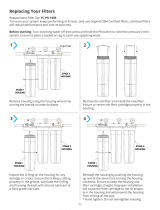
V. Membrane Replacement
1. Turn off the system and close the feed water shutoff valve.
2. Unplug the unit.
3. Disconnect the tubing from the top of the membrane housing(s).
4. Loosen the clamps and remove the top end cap(s).
5. Remove the old membrane(s) by pulling them up and out of the
housings. You may need to grab the old by the membrane with
a pair of pliers.
6. Install the new membrane(s) in the housing(s) and replace the
end caps. The new membranes should be installed in the same
orientation as the old membranes.
Note: It is very important that the brine seal does not flip up or roll
when installing the membrane brine seal first. Use plenty of glycerin
lubricant and use a gentle twisting/rocking motion as you slide the
membrane in. If you are unable to install the membrane brine seal
first without rolling the seal then lay the unit over, remove the bottom
end cap, and install the membrane brine seal last.
7. Reconnect the tubing to the bottom of the membrane
housing(s).
8. Follow the start up procedure in section III-D.
Brine
Seal
Flow Direction
Membrane
°C °F CORRECTION FACTOR
30 86 1.16
29 84.2 1.13
28 82.4 1.09
27 80.6 1.06
26 78.8 1.03
25 77 1.00
24 75.2 0.97
23 73.4 0.94
22 71.6 0.92
21 69.8 0.89
20 68 0.86
19 66.2 0.84
18 64.4 0.81
17 62.6 0.79
16 60.8 0.77
15 59 0.74
14 57.2 0.72
13 55.4 0.70
12 53.6 0.68
11 51.8 0.66
10 50 0.64
9 48.2 0.62
8 46.4 0.61
7 44.6 0.59
6 42.8 0.57
5 41 0.55
Multiply the nominal product flow at 25°C by the temperature correction factor to
determine the flow at various other temperatures.
VI. Appendix
The following tables are intended as a guide to determining the flow
rates for the PWRO440 Series RO systems. All flows are in gallons
per minute (GPM) with 77°F feed water.
Nominal flows for systems operating at 50% recovery with a
feed water SDI < 1.
Nominal flows for systems operating at 50% recovery with a
feed water SDI < 3.
Nominal flows for systems operating at 50% recovery with a
feed water SDI < 5.
MODEL NUMBER PWRO4401 PWRO4402 PWRO4403
Product GPM 1.5 3.0 4.5
Reject GPM 1.5 3.0 4.5
MODEL NUMBER PWRO4401 PWRO4402 PWRO4403
Product GPM 1.25 2.5 3.75
Reject GPM 1.25 2.5 3.75
MODEL NUMBER PWRO4401 PWRO4402 PWRO4403
Product GPM 1 2 3
Reject GPM 1 2 3
Temperature Correction Factors

IOM-WQ-PWRO440 1826 EDP# 2915877 © 2018 Watts
USA: Tel. (800) 224-1299 • www.watts.com
Canada: Tel. (888) 208-8927 • www.watts.ca
A Watts Water Technologies Company
LIMITED WARRANTY: Certain Watts Pure Water products come with a limited warranty from Watts Regulator Co. Other products may have no warranty or are covered by the original manufacturer’s
warranty only. For specific product warranty information, please visit www.watts.com or the published literature that comes with your product. Any remedies stated in such warranties are exclusive and
are the only remedies for breach of warranty. EXCEPT FOR THE APPLICABLE PRODUCT WARRANTY, IF ANY, WATTS MAKES NO OTHER WARRANTIES, EXPRESS OR IMPLIED. TO THE FULLEST EXTENT
PERMITTED BY APPLICABLE LAW, WATTS HEREBY SPECIFICALLY DISCLAIMS ALL OTHER WARRANTIES, EXPRESS OR IMPLIED, INCLUDING BUT NOT LIMITED TO THE IMPLIED WARRANTIES OF
MERCHANTABILITY AND FITNESS FOR A PARTICULAR PURPOSE, AND IN NO EVENT SHALL WATTS BE LIABLE, IN CONTRACT, TORT, STRICT LIABILITY OR UNDER ANY OTHER LEGAL THEORY, FOR
INCIDENTAL, INDIRECT, SPECIAL OR CONSEQUENTIAL DAMAGES, INCLUDING, WITHOUT LIMITATION, LOST PROFITS OR PROPERTY DAMAGE, REGARDLESS OF WHETHER IT WAS INFORMED ABOUT
THE POSSIBILITY OF SUCH DAMAGES.
/