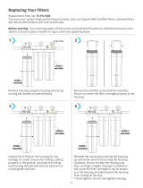
C. Pretreatment
The RO feed water must be pretreated in order to prevent mem-
brane damage and/or fouling. Proper pretreatment is essential for
reliable operation of any RO system.
Pretreatment requirements vary depending on the nature of the feed
water. Pretreatment equipment is sold separately. The most common
forms of pretreatment are described below.
Media Filter - Used to remove large suspended solids (sediment)
from the feed water. Backwashing the media removes the trapped
particles. Backwash can be initiated by time or differential pressure.
Water Softener - Used to remove calcium and magnesium from
the feed water in order to prevent hardness scaling. The potential
for hardness scaling is predicted by the Langelier Saturation Index
(LSI). The LSI should be zero or negative throughout the unit unless
approved anti-scalents are used. Softening is the preferred method
of controlling hardness scale.
Carbon Filter - Used to remove chlorine and organics from the
feed water. Free chlorine will cause rapid irreversible damage to the
membranes.
The residual free chlorine present in most municipal water supplies
will damage the thin film composite structure of the membranes
used in this unit. Carbon filtration or sodium bisulfite injection should
be used to completely remove the free chlorine residual.
Chemical Injection - Typically used to feed anti-scalant, coagulant,
or bisulfite into the feed water or to adjust the feed water pH.
Prefilter Cartridge - Used to remove smaller suspended solids and
trap any particles that may be generated by the other pretreatment.
The cartridge(s) should be replaced when the pressure drop across
the housing increases 5 - 10 psig over the clean cartridge pressure
drop. The effect of suspended solids is measured by the silt density
index (SDI) test. An SDI of five (5) or less is specified by most mem-
brane manufacturers and three (3) or less is recommended.
Iron & Manganese - Iron should be removed to less than 0.1 ppm.
Manganese should be removed to less than .05 ppm. Special media
filters and/or chemical treatment is commonly used.
pH - The pH is often lowered to reduce the scaling potential.
Silica: Reported on the analysis as SiO2. Silica forms a coating on
membrane surfaces when the concentration exceeds its solubility.
Additionally, the solubility is highly pH and temperature dependent.
Silica fouling can be prevented with chemical injection and/or reduc-
tion in recovery.
2
I. Introduction
The separation of dissolved solids and water using RO membranes
is a pressure driven temperature dependent process. The membrane
material is designed to be as permeable to water as possible, while
maintaining the ability to reject dissolved solids.
The main system design parameters require the following:
• Internal flows across the membrane surface must be high enough
to prevent settling of fine suspended solids on the membrane
surface.
• The concentration of each dissolved ionic species must not exceed
the limits of solubility anywhere in the system.
• Pre-treatment must be sufficient to eliminate chemicals that would
attack the membrane materials.
PWR40113012 PWR40113022 PWR40113032
Maximum Productivity
(gallons per day / gallons per
minute)
Maximum production based
on a feed water of 25°C, SDI
< 3, 1000 ppm TDS, and pH
8. Individual membrane pro-
ductivity may vary (± 15%).
May be operated on other
feed waters with reduced
capacity.)
1800 / 1.25 3600 / 2.5 5400 / 3.75
Quality (Typical Membrane
Percent Rejection)
Based on membrane manu-
factures specifications; over-
all system percent rejection
may be less.
98 % 98 % 98 %
Recovery (adjustable) 50 - 75 % 50 - 75 % 50 - 75 %
Membrane Size 4" x 40" 4" x 40" 4" x 40"
Number Of Membranes Per
Vessel
1 1 1
Pressure Vessel Array 1 1:1 1:1:1
Number Of Membranes 1 2 3
Prefilter (system ships with
one 5 micron cartridge)
10" BB 10" BB 10" BB
Feed Water Connection 1" NPT 1" NPT 1" NPT
Product Water Connection 1/2" Tubing 1/2" Tubing 5/8" Tubing
Reject Water Connection 1/2" Tubing 1/2" Tubing 1/2" Tubing
Feed Water Required
(at 50% recovery)
2.5 gpm 5 gpm 7.5 gpm
Feed Water Pressure
(minimum)
20 psi 20 psi 20 psi
Drain Required (maximum) 10 gpm 10 gpm 10 gpm
Electrical Requirement
(Other voltages available)
120 VAC 60 Hz
18 amps
120 VAC 60 Hz
18 amps
120 VAC 60 Hz
27 amps
Motor Horse Power 1 1 1.5
Dimensions L x H x D
(inches)
41 x 51 x 18 41 x 51 x 18 49 x 51 x 18
Shipping Weight
(estimated pounds)
200 250 300
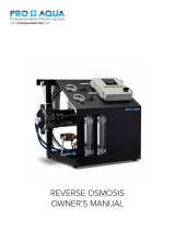
A. Specifications
RO Membrane
Feed Water Product Water
Reject Water
B. RO Overview
Reverse osmosis systems utilize semipermeable membrane ele-
ments to separate the feed water into two streams. The pressurized
feed water is separated into purified (product) water and concentrate
(reject) water. The impurities contained in the feed water are carried
to drain by the reject water.