Ames Fire & Waterworks 0690995 Installation guide

Type
Installation guide
RP/IS-A-4000SS/5000SS
4000SS
Installation, Maintenance, & Repair
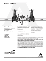
Series 4000SS/5000SS
Reduced Pressure Zone Assemblies & Reduced Pressure Detector Assemblies
Sizes: 2
1
2" – 6" (65 – 150mm)**
NOTICE
For Australia and New Zealand, line strainers should be installed
between the upstream shutoff valve and the inlet of the backflow
preventer.
NOTICE
The flange gasket bolts for the gate valves should be
retightened during installation as the bolts may have loosened
due to storage and shipping.
Testing
For field testing procedure, refer to Ames installation sheets
IS-A-ATG-1 found on www.amesfirewater.com.
For other repair kits and service parts, refer to our Backflow
Prevention Products Repair Kits & Service Parts price list
PL-A-RP-BPD found on www.amesfirewater.com.
For technical assistance, contact your local Ames representative.
** Metric Dimensions are nominal pipe diameter. This product is produced with
ASME/ANSI flanged end connections.
WARNING
!
Read this Manual BEFORE using this equipment.
Failure to read and follow all safety and use information can
result in death, serious personal injury, property damage, or
damage to the equipment.
Keep this Manual for future reference.
You are required to consult the local building and plumbing
codes prior to installation. If the information in this manual
is not consistent with local building or plumbing codes,
the local codes should be followed. Inquire with governing
authorities for additional local requirements.
WARNING
!
Need for Periodic Inspection/Maintenance: This product must
be tested periodically in compliance with local codes, but at least
once per year or more as service conditions warrant. If installed on
a fire suppression system, all mechanical checks, such as alarms
and backflow preventers, should be flow tested and inspected in
accordance with NFPA 13 and/or NFPA 25. All products must be
retested once maintenance has been performed. Corrosive water
conditions, and/or unauthorized adjustments or repair could render
the product ineffective for the service intended. Regular checking
and cleaning of the product’s internal components helps assure
maximum life and proper product function.
WARNING
!
www.amesfirewater.com
A Watts Water Technologies Company
WARNING
!
The installation and maintenance of backflow assemblies
should be performed by a qualified, licensed technician.
Failure to do so may result in a malfunctioning assembly.
2
Outdoor Installation
NOTICE
The flange gasket bolts for the gate valves should be
retightened during installation as the bolts may have loosened
due to storage and shipping.
NOTICE
Assembly body should not be painted.
Please Read Prior to Installation:
1. Before installing any Ames assembly, Flush the Line thoroughly
to remove all debris, chips and other foreign objects. Failure to
do so may make the assembly inoperable.
2. The Ames 4000SS and 5000SS Reduced Pressure Zone As-
semblies are approved by ASSE (American Society of Sanitation
Engineers) to be installed in horizontal positions. Local water
authorities must approve all installation configurations.
3. Allow sufficient clearance around the installed assembly to
conduct testing, servicing, and inspection. Allow a minimum of 12"
from the flood level to the bottom of the assembly.
4. The 4000SS and 5000SS are not recommended for pit installa-
tions. Where necessary, an Air Gap drain may be connected to
the relief valve to minimize flooding of the surrounding area. Flood-
ing may cause a cross-connection. Be sure to contact local code
authorities for proper installations.
5. If installing on fire protection system, be sure to purge air from fire
system. Fill system slowly with all inspectors test valves open.
Installation Guidelines
Item # Description
1. #1 Cam-Check
2. #2 Cam-Check
3. #1 Cam-Check O-ring
4. #2 Cam-Check O-ring
5. Cover Plate
6. Ball Valve
7. Groove Coupler
Item # Description
8. Groove Coupler Gasket
9. Relief Valve
(Complete assembly)
10. Relief Valve Hose
11. Relief Valve Body O-ring
12. Ball Valve (Cover)
Figure 1
Flow
1
2
3
4
5
6
7
8
9
11
10
12
Indoor Installation
3
WARNING
!
Depressurize valve before servicing.
Removing Cam-Checks
1. Shut down water system and lock out system if possible. Slowly
open all ball valves to relieve air and water pressure. Loosen
bolts on groove coupler and remove groove coupler and cover
plate from valve body.
2. Remove #1 Cam-Check Assembly by using your hands to
unscrew (turn counterclockwise) Cam-Check and remove
through top access port. Do not use Cam Arm as a handle
to unscrew Cam-Check. If Cam-Check cannot be loosened
by hand, insert a long screwdriver between valve body and
Cam-Check (see Figure 3). Gently apply pressure against the
Cam-Check until loosened. Finish unscrewing by hand. Un-
screw #2 Cam-Check (turn counterclockwise) by placing a long
screwdriver across lugs and applying pressure to loosen #2
Cam-Check. Finish unscrewing by hand.
3. To clean #1 Cam-Check (except 2
1
/2" – 4" (65-100mm) DC
Check), locate the Cam Arm opening stud on the outlet flange
of the valve assembly. Slide the Cam Arm over the stud with the
check threads facing downward (Figure 5A). Tighten
1
/4" nut on
stud to secure cam bar. Slowly pull the assembly outward to
open check. The clapper so that the end of the Cam Arm rests
between roller and clapper (Figure 5B).
Thoroughly clean the seat area and clapper sealing surfaces of
both Cam-Checks. Rinse Cam-Checks and O-rings thoroughly.
Inspect seats, clapper sealing surfaces, Cam Arms, and O-rings
for damage, nicks, and debris. If damaged, install a new Cam-
Check assembly and/or O-ring or shutoff disc.
4. Before reinstallation of check assembly, thoroughly clean
O-ring groove and lubricate with F.D.A. approved lubricant.
Insert and thread #2 Cam-Check first and then #1 Cam-Check.
#2 Cam-Check should be tightened by inserting a long screw-
driver between lugs to tighten firmly (see Figure 2). Do not over
tighten. Tighten #1 Cam-Check firmly by hand only. Replace
cover plate, clean groove coupler gasket and groove. Replace
groove coupler. Close ball valves. Repressurize and bleed air
from all test cocks.
Maintenance Instructions
Figure 2
#1 Cam
Check
#2 Cam
Check
Screwdriver
A
B
C
#1 Cam Check
2
1
/2" – 6" (65-150mm) RP (Short Cam)
Figure 3
O-ring Seal
& Groove
Seat Clapper
Roller
Spring
Cam Arm
Figure 4
#2 Cam Check DC & RP
O-ring Seal
& Groove
Lug
Seat
O-ring Seal & Groove
Clapper
6" Only
Roller
Cam Arm
Spring
Figure 5A
Cam Bar Open Pin
Valve Outlet Flange
Threaded Stud on Flange
6" (150mm) 1st Check DC
6" (150mm) 2nd Check
DC & RP
Figure 5B
Cleaning
Position
For repair kits and parts, refer to our Backflow Pre-
vention Products Repair Kits & Service Parts price list
PL-A-RP-BPD found on www.amesfirewater.com.
4
Relief Valve Service Instructions
WARNING
!
Depressurize valve before servicing.
The relief valve may be serviced while on or off the backflow pre-
venter valve.
NOTICE
Do not use a pipe wrench to remove the relief valve assembly
from the backflow preventer.
Relief Valve Disassembly
1. Disconnect the relief valve hose from the elbow in the bottom
flange cover at the swivel hose connection. Do not remove the
elbow.
2. If the valve is to be removed from the backflow preventer for
service, place a screwdriver blade or flat bar across the edges
of 2 of the hex head screws in the bottom flange cover and
turn counterclockwise to loosen the relief valve assembly. (see
Figure 2)
3. Remove the 4 bottom bolts from the bottom of the relief valve
assembly with a
5
/16" socket or open-end wrench. Remove the
bottom flange cover.
4. Remove the piston assembly & sleeve from the relief valve body
by placing your index fingers through the slots in the side of the
body and pressing down on the top of the disc retainer in the
top of the piston assembly. (See Figure 7.)
5. Pull the piston assembly free of the body by grasping the sleeve
and pulling down.
6. Grip the sleeve and the piston assembly by the head of the hex
head bolt. Pull up on the sleeve to extend the diaphragm. Slide
the sleeve (Part #7013340) completely off of the diaphragm and
inspect the diaphragm for tears, holes or excessive wrinkles. If
the diaphragm is damaged, order a new piston/diaphragm as-
sembly.
Relief Valve Reassembly
1. Thoroughly clean all inside surfaces of the relief valve body.
2. Inspect the relief valve body seat surface located at the top
edge of the 3 discharge slots near the top of the body by rub-
bing the end of the index finger around the entire seat surface;
access the seat surface through the slots or the bottom of the
body. The seat must be free of nicks. If nicks are discovered,
remove the body & install a new relief valve assembly.
3. Position the diaphragm on the piston assembly so that it is fac-
ing up as shown in Figure 8.
4. Now fold the top (ribbed) edge of the diaphragm inward, grasp
the sleeve with the ribbed edge up and slide the sleeve down
over the piston assembly as shown in Figure 8.
5. While still holding the sleeve, slide it up over the diaphragm and,
using your thumb & index finger, position the bead of the dia-
phragm so that it wraps over the outside of the rib on the top
of the sleeve so that the sleeve is held by the diaphragm. Now
place the piston assembly on a flat, firm surface with diaphragm
facing up as shown in Figure 9.
6. Cup your hand slightly to form an air trap and force the sleeve
down over the piston assembly with a rapid slap (hard) on
the open end of the diaphragm with your cupped hand. The
trapped air in the diaphragm will force the diaphragm between
the inside of the sleeve and the outside of the piston. Ensure
that the diaphragm is fully seated by running the end of a dull
“butter” knife in the formed diaphragm. If diaphragm is wrinkled,
repeat previous step.
7. Slide the piston assembly and sleeve into the relief valve body
with the hex head bolt entering the flanged end of the body
first. Slide the piston assembly in until the diaphragm lip is
smoothly seated in the machined groove in the flanged end of
the body. By running your index finger around the outside of
the diaphragm bead, you will ensure it is seated smoothly.
8. Position the bottom flange cover on the bottom of the relief
valve body and secure by hand tightening the 4 bottom bolts.
9. Now tighten the 4 bottom bolts to approximately 15 ft.-lbs. with
a
5
/16" socket or open-end wrench.
10. Reattach the relief valve hose to the elbow in the bottom flange
cover.
5
Figure 6
Item # Part Description
21. Relief Valve Body
22.* Rubber Shut-Off Disc.
23.* Piston Diaphragm Assembly
24. Hex Head Bolt
25. Disc. Retainer
26. Sleeve
27. Bottom Bolt
28. Bottom Flange (w/St. Elbow)
29. Elbow St 90 3/8
30.* O-Ring Disk
31. RV Spring
Figure 9
Figure 6
Figure 7
Figure 8
Relief Valve
31
21
22
24
30
25
26
28
29
23
27
6
Test No.1
Purpose: To test check valve No. 2 for tightness against reverse
flow.
Requirements: Valve must be tight against reverse flow under
all pressure differentials. Slowly open the ‘high’ valve A and the
‘vent’ valve C, and keep the ‘low’ valve B closed. Open test
cock #4. Indicated pressure differential will decrease slightly. If
pressure differential continues to decrease (until the vent opens)
check valve #2 is reported as ‘leaking’.
Test No. 2
Purpose: To test shutoff #2 for tightness.
Requirements: After passing Test No. 1, continue to Test No. 2
by closing test cock #2. The indicated pressure differential will
decrease slightly. If pressure differential continues to decrease
(approaching ‘zero’), shutoff #2 is reported to be ‘leaking’.
Test No. 3
Purpose: To test check Valve No. 1 for tightness.
Requirements: Valve must be tight against reverse flow under
all pressure differentials. Close ‘high’ valve A and open test cock
#2. Close test cock #4. Disconnect vent hose at test cock #4.
Open valves B and C, bleeding to atmosphere. Then closing valve
B restores the system to a normal static condition. Observe the
pressure differential gauge. If there is a decrease in the indicated
value, check valve No. 1 is reported as ‘leaking’.
Test No. 4
Purpose: To test operation of pressure differential relief valve.
Requirements: The pressure differential relief valve must
operate to maintain the ‘zone’ between the two check valves
at least 2psi less than the supply pressure. Close ‘vent’ valve
C. Open ‘high’ valve A. Open the ‘low’ valve B very slowly until
the differential gauge needle starts to drop. Hold the valve at
this position and observe the gauge reading at the moment the
first discharge is noted from the relief valve. Record this as the
opening differential pressure of the relief valve.
NOTICE
It is important that the differential gauge needle drops slowly.
Close test cocks #2 and #3. Use ‘vent’ hose to relieve pressure
from test kit by opening valves A, B and C. Remove all test
equipment and open shutoff #2.
CAUTION
!
To prevent freezing, hold Test Kit vertically to drain differential
gauge and hoses prior to placing in case.
Testing — Reduced Pressure Zone Assemblies
Ball Type Test Valves
(A)
(C)
(B)
Needle
Valve
High Hose
(Yellow)
Low Hose
(White or Red)
Vent Hose
(Blue)
Test Cock
No. 1
Test Cock
No. 2
Test Cock
No. 3
Test Cock
No. 4
Auxiliary
Test Cock
7
Problem Identification Procedures
Troubleshooting Guide
PROBLEM CAUSE SOLUTION
A. Assembly discharges from differential
relief valve during no flow condition.
Fouled first check
Fluctuating inlet pressure
Outlet pressure higher than inlet pressure
& leak in No. 2 check valve
Leak through diaphragm or around flange
bolt holes of relief valve
Pressure relief valve does not close
Disassemble and clean No. 1check valve
Control supply line water pressure
Disassemble, clean #2 check valve &
identify cause of back pressure.
Service relief valve (page 3)
See problem D
B. Assembly discharges from differential
relief valve during a flow condition.
No. 1 check valve wedged open
O-ring displaced from groove in 1st check
Pressure relief valve does not close
Fluctuating line pressure
Disassemble and clean No. 1 check valve
Disassemble and replace
See problem D
C. Differential pressure relief valve does
not open during test due to leaking
outlet gate valve.
Differential pressure across No. 1 check
valve stays above 2psi due to leaking
outlet gate valve
Weak or broken relief valve spring
Shut off seat tube bound in body
Plugged hydraulic hose
Repair shut-off valves
Disassemble and replace relief valve spring
Disassemble and repair
D. Pressure relief valve does not close Debris on sealing surface
Plugged hydraulic hose
Damaged seat or rubber shut off disc
Ruptured diaphragm
Wrinkled or improperly installed diaphragm
Remove relief valve and clean
Disassemble and clean
Remove relief valve assembly and replace
Disassemble and replace diaphragm
Disassemble and properly position
diaphragm
When using differential pressure gauge:
A. Check differential across No. 1 check valve
READING PROBLEM
2 to 3 psid Leak in No. 1 or No. 2 check valve
4 to 7 psid and steady Malfunctioning pressure relief valve
2 to 7 psid Inlet pressure fluctuation
Without using differential pressure gauge:
A. Close gate valve No. 2
RESULT PROBLEM
If discharge stops Leak in No. 2 check valve
If discharge does not stop Go to B
B. Open No. 4 testcock to produce a flow greater than
differential relief valve discharge
RESULT PROBLEM
If discharge stops Leak in No. 1 check valve
If discharge does not stop Malfunctioning pressure relief valve
For additional information, visit our web site at: www.amesfirewater.com
RP/IS-A-4000SS/5000SS 1326 EDP# 7016813 © 2013 Ames Fire & Waterworks
www.amesfirewater.com
A Watts Water Technologies Company
USA: Backflow- Tel: (916) 928-0123 Fax: (916) 928-9333
Control Valves- Tel: (713) 943-0688 Fax: (713) 944-9445
Canada: Tel: (905) 332-4090 Fax: (905) 332-7068
Limited Warranty: Ames Fire & Waterworks (the “Company”) warrants each product to be free from defects in material and workmanship under normal usage for a period of one year from the date
of original shipment. In the event of such defects within the warranty period, the Company will, at its option, replace or recondition the product without charge.
THE WARRANTY SET FORTH HEREIN IS GIVEN EXPRESSLY AND IS THE ONLY WARRANTY GIVEN BY THE COMPANY WITH RESPECT TO THE PRODUCT. THE COMPANY MAKES NO OTHER
WARRANTIES, EXPRESS OR IMPLIED. THE COMPANY HEREBY SPECIFICALLY DISCLAIMS ALL OTHER WARRANTIES, EXPRESS OR IMPLIED, INCLUDING BUT NOT LIMITED TO THE IMPLIED
WARRANTIES OF MERCHANTABILITY AND FITNESS FOR A PARTICULAR PURPOSE.
The remedy described in the first paragraph of this warranty shall constitute the sole and exclusive remedy for breach of warranty, and the Company shall not be responsible for any incidental, special
or consequential damages, including without limitation, lost profits or the cost of repairing or replacing other property which is damaged if this product does not work properly, other costs resulting
from labor charges, delays, vandalism, negligence, fouling caused by foreign material, damage from adverse water conditions, chemical, or any other circumstances over which the Company has no
control. This warranty shall be invalidated by any abuse, misuse, misapplication, improper installation or improper maintenance or alteration of the product.
Some States do not allow limitations on how long an implied warranty lasts, and some States do not allow the exclusion or limitation of incidental or consequential damages. Therefore the above
limitations may not apply to you. This Limited Warranty gives you specific legal rights, and you may have other rights that vary from State to State. You should consult applicable state laws to
determine your rights. SO FAR AS IS CONSISTENT WITH APPLICABLE STATE LAW, ANY IMPLIED WARRANTIES THAT MAY NOT BE DISCLAIMED, INCLUDING THE IMPLIED WARRANTIES OF
MERCHANTABILITY AND FITNESS FOR A PARTICULAR PURPOSE, ARE LIMITED IN DURATION TO ONE YEAR FROM THE DATE OF ORIGINAL SHIPMENT.
WARNING: This product contains chemicals known to the
State of California to cause cancer and birth defects or
other reproductive harm.
For more information: www.watts.com/prop65
  • Page 1 1
  • Page 2 2
  • Page 3 3
  • Page 4 4
  • Page 5 5
  • Page 6 6
  • Page 7 7
  • Page 8 8

Ames Fire & Waterworks 0690995 Installation guide

Type
Installation guide

Ask a question and I''ll find the answer in the document

Finding information in a document is now easier with AI