ALUMINUM GATE
INSTALLATION INSTRUCTIONS
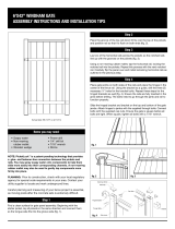
Measure opening between posts. Opening may not exceed 48".
The gate hinges can accommodate gaps from 1/4"-7/8", but
3/4" is ideal. The latch can accommodate gaps from 3/8"-1-3/4".
Determine the desired spacing and subtract from opening. 1-3/4"
is recommended but can range from 5/8" to 2-1/2" (fig. 1).
Measure gate and determine amount to be trimmed. Lay gate
panel (A) on a flat, non-marring surface. Remove latch post (B)
from gate (fig. 2).
Step 1
Step 2
Step 3
Items you will need
• Drill/power screwdriver
• Miter or circular saw
with carbide tip blade
• Marked speed square
• Carpenter's level
• Carpenter's pencil
Contents
• 1 – 36" tall x 45-1/2" wide deck gate with welded hinge post (A)
• 1 – Latch post with splice and fasteners (B)
• 2 – Post caps (C)
• 1 – Toggle latch (D)
• 2 – Tru-close hinges with fasteners (E)
fig. 1
48" max. width
1/4" to 7/8"
3/4" Ideal
3/8" to 1-3/4"
Gate width plus 1-3/4" is ideal
•• ••
•
• •
3" high blocks typical
GateDim.ai
GateAsm.ai
fig. 2
Latch side
GateCut.ai
•
•
Cut top and bottom the
same to adjust size
©2015 Universal Forest Products, Inc. All rights reserved.
US Route 202, Greene, ME 04236 8559_11/15
www.ufpi.com
• Adjustable wrench or socket
wrench
• Safety glasses/goggles
• Rubber mallet
• Tape measure
Latch side
GateExpl.ai
Latch
•
•
•
•
•
Post cap
Hinge side
Hinge
A
B
C
D
E

THE DIAGRAMS AND INSTRUCTIONS IN THIS BROCHURE ARE FOR ILLUSTRATION PURPOSES ONLY AND ARE NOT MEANT TO REPLACE A LICENSED PROFESSIONAL. ANY CONSTRUCTION OR USE OF
THE PRODUCT MUST BE IN ACCORDANCE WITH ALL LOCAL ZONING AND/OR BUILDING CODES. THE CONSUMER ASSUMES ALL RISKS AND LIABILITY ASSOCIATED WITH THE CONSTRUCTION OR USE
OF THIS PRODUCT. THE CONSUMER OR CONTRACTOR SHOULD TAKE ALL NECESSARY STEPS TO ENSURE THE SAFETY OF EVERYONE INVOLVED IN THE PROJECT, INCLUDING, BUT NOT LIMITED TO,
WEARING THE APPROPRIATE SAFETY EQUIPMENT. EXCEPT AS CONTAINED IN THE WRITTEN LIMITED WARRANTY, THE WARRANTOR DOES NOT PROVIDE ANY OTHER WARRANTY, EITHER EXPRESS
OR IMPLIED, AND SHALL NOT BE LIABLE FOR ANY DAMAGES, INCLUDING CONSEQUENTIAL DAMAGES.
©2015 Universal Forest Products, Inc. All rights reserved.
US Route 202, Greene, ME 04236 8559_11/15
www.ufpi.com
Make sure gate is plumb and level and attach hinges (E) to post.
Determine location of latch (D) on the latch post (B). Assemble the
latch for right-hand or left-hand operation.
Check for level and attach latch to latch post, using screws
positioned in the center of the screw slots.
Close the gate and using a level, mark the top of the latch on the
adjacent post. Position the catch and attach to adjacent post (fig. 3).
Ensure proper operation of the gate. Hinge tension is adjustable.
See hardware kit instructions for details.
Place precut blocks back underneath the bottom rail for support.
Tap the post caps (C) onto the gate posts using a rubber mallet.
Step 8
Step 9
Step 10
Step 11
Step 12
Step 13
The hinge post (A) is welded to the panel for best long-term
performance. Attach hinges (E) to the hinge post at each rail location.
Prop the gate by positioning precut blocks beneath the bottom rail and
between the posts (fig. 1). Spacing of 3" is typical but can be more or
less as allowed by local building codes. Per the model building code,
all gaps must be less than 4". Ensure bottom of gate posts will be high
enough to clear any obstacles, such as post base trims, if applicable.
Step 6
Step 7
ALUMINUM GATE INSTALLATION INSTRUCTIONS, CONT.
GateLatch.ai
fig. 3
Cut top and bottom rails to the same length.
Attach the latch post (B) to the gate panel (A) using 2 screws through
the underside of the top and bottom rails into the splice on the latch
post (fig. 2). Use care to avoid marring the post with the drill chuck.
Turning the gate upside down may make this step easier.
Step 4
Step 5
Page is loading ...
Page is loading ...
Page is loading ...
Page is loading ...
/


