Page is loading ...

Eaton
®
BladeUPS
®
DoS Installation Instructions


Eaton
®
BladeUPS
®
DoS Installation Instructions

Help Desk Numbers
United States 1-800-356-5737 or 1-800-843-9433
Canada 1-800-461-9166 ext 260
All Other Countries Call your local service representative
Web sites:
l
www.eaton.com/powerquality
NOTE: On the Web site opening page, click Support and select the
Customer Service link for more information.
Eaton, BladeUPS, and X-slot are registered trademarks of Eaton Corporation or
its subsidiaries and affiliates. Phillips is a registered trademark of Phillips Screw
Company. All other trademarks are property of their respective companies.
©Copyright 2019 Eaton Corporation, Raleigh, NC, USA. All rights reserved. No
part of this document may be reproduced in any way without the express written
approval of Eaton Corporation.

Eaton BladeUPS DoS Installation Instructions P-164000613—Rev 3 i
Table of Contents
Introduction . . . . . . . . . . . . . . . . . . . . . . . . . . . . . . . . . . . . . . . . . . . . . . . . 1
System Components. . . . . . . . . . . . . . . . . . . . . . . . . . . . . . . . . . . . . . . . . . 1
Tools . . . . . . . . . . . . . . . . . . . . . . . . . . . . . . . . . . . . . . . . . . . . . . . . . . . . . . 4
Moving the System and Battery Pallets . . . . . . . . . . . . . . . . . . . . . . . . . . . 5
Unpacking . . . . . . . . . . . . . . . . . . . . . . . . . . . . . . . . . . . . . . . . . . . . . . . . . . 5
Unloading the System . . . . . . . . . . . . . . . . . . . . . . . . . . . . . . . . . . . . . . . . 6
Equipment Setup . . . . . . . . . . . . . . . . . . . . . . . . . . . . . . . . . . . . . . . . . . . . 9
Install the Equipment Modules and Batteries . . . . . . . . . . . . . . . . . . . . . . 11
Wiring and Cabling . . . . . . . . . . . . . . . . . . . . . . . . . . . . . . . . . . . . . . . . . . . 13
System Startup . . . . . . . . . . . . . . . . . . . . . . . . . . . . . . . . . . . . . . . . . . . . . . 20
Specifications . . . . . . . . . . . . . . . . . . . . . . . . . . . . . . . . . . . . . . . . . . . . . . . 21

Table of Contents
ii Eaton BladeUPS DoS Installation Instructions P-164000613—Rev 3

Eaton BladeUPS DoS Installation Instructions P-164000613—Rev 3 1
Section 1 Introduction
If any equipment has been damaged during shipment, keep the shipping cartons and packing materials for the
carrier or place of purchase, and file a claim for shipping damage. If you discover damage after acceptance, file
a claim for concealed damage.
To file a claim for shipping damage or concealed damage: 1) File with the carrier within 15 days of receipt of
the equipment; 2) Send a copy of the damage claim within 15 days to your service representative.
System Components
The equipment components of the BladeUPS system are shipped as follows:
l
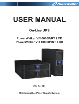
1 palletized BladeUPS Cabinet (see Figure 1)
l
1 palletized Transformer (not needed if you are using an existing transformer or not using a transformer; see
Figure 1)
Figure 1. BladeUPS Cabinet and Transformer (if ordered)
l
2 BladeUPS shipping cartons (see Figure 1 and Figure 2 for more information)

2 Eaton BladeUPS DoS Installation Instructions P-164000613—Rev 3
Table 1. Shipped in Each Shipping Carton
Quantity Description
1 BladeUPS Module Chassis (delivered with
Electronics Module installed)
1 Electronics Module
4 Battery Packs
1 package UPS Documentation and Software Tools:
l
IPSS Software Suite CD and Firmware CD
l
Installation instructions and a standard
BladeUPS User’s Guide
2 Door Keys

Eaton BladeUPS DoS Installation Instructions P-164000613—Rev 3 3
2 Hot Sync CAN Bridge Cards
1 CAN Bridge Card Cable
1 Redundant Signal Cable
1 Input-Output Wire
2 Blue Terminating Plugs
1 Bypass Switch Contact Cable
Table 1. Shipped in Each Shipping Carton (Continued)
Quantity Description

4 Eaton BladeUPS DoS Installation Instructions P-164000613—Rev 3
Figure 2. BladeUPS Shipping Carton
Section 2 Tools
To assemble the components, you may need the following tools:
l
Forklift or pallet jack
l
Flathead (short and long)
l
Short- and long-handled medium flat-bladed screwdriver
l
Short- and long-handled #2 Phillips® screwdriver
l
Ratcheting socket wrench and socket for 9/16" screws
l
7 mm wrench or socket
l
Utility knife
l
Adjustable pliers
2 Two-screw Brackets
2 Ferrite Cores
1 package Assorted jumpers for REPO (see the standard
BladeUPS manual)
May include 2-pin or 3-pin jumpers
Table 1. Shipped in Each Shipping Carton (Continued)
Quantity Description

Eaton BladeUPS DoS Installation Instructions P-164000613—Rev 3 5
l
Wire cutter for tie wraps
Note: You may find it useful to use a magnetized screwdriver when removing or replacing mounting screws.
Section 3 Moving the System and Battery Pallets
The BladeUPS cabinet is bolted to a wooden pallet and shrink-wrapped for traveling. If you are installing a new
transformer, it is also bolted to a separate wooden pallet. The batteries and the BladeUPS modules are packed
in two separate boxes with other accessory boxes within larger containers on a separate pallet.
WARNING
The forklift jacks must be inserted between the skids at the front of the pallet. If unloading instructions
are not closely followed, moving the pallets may cause serious injury.
To move the equipment and boxes on the pallets:
1. Verify that the forklift or pallet jack you will use is rated to handle the weight of the equipment or loaded
boxes and the pallet.
2. If not already moved, use a forklift or pallet jack to move the pallets to the installation area, or as close as
possible.
Note: Insert the forklift jacks between the skids at the front of the pallet.
Note: Do not park the pallet in a location that will interfere with installing the system.
Section 4 Unpacking
Note: Some set ups will be retrofitting their transformer configuration with a BladeUPS cabinet instead of
another type of Eaton UPS. If so, make sure the Eaton UPS bolted to the top of the transformer is
removed per your facility practice before unpacking the BladeUPS shipping cartons.
To unpack the equipment:
1. Remove the shrink wrap from the BladeUPS cabinet.
2. Cut the carton tie wraps with the wire cutters and open the two BladeUPS shipping cartons by lifting off
the top containment (see Figure 3).

6 Eaton BladeUPS DoS Installation Instructions P-164000613—Rev 3
Figure 3. Unpacking a BladeUPS Shipping Carton
3. Check each shipping carton to identify the contents.
Note: Some of the boxes are empty. They are in the stack to prevent voids inside the shipping carton that
would allow the contents to shift. Discard per your practice, or store for future use.
Section 5 Unloading the System
Note: Front and rear stabilizing bolts are bolted through the floor of the cabinet into the pallet to secure the
system for shipping. The bolts must be removed before unloading the system.
1. Unlock the BladeUPS cabinet and place the key in a secure place so it will be available to you when you
need it.
2. Open the BladeUPS cabinet front door.
3. Ensure the UPS/Service/Bypass switch dial is turned to UPS (see Table 2 and Figure 4).
Table 2. UPS Bypass Switch Positions
Switch Position Description
UPS Connects the UPS output to the load.
SERVICE Connects the load directly to AC input power and disconnects UPS output. AC
input power is still connected to the UPS input.
BYPASS Like the SERVICE position, BYPASS connects the load directly to AC input power
and disconnects UPS output. However, because BYPASS also disconnects AC
input from the UPS, this is the appropriate position for UPS maintenance or
repair.

Eaton BladeUPS DoS Installation Instructions P-164000613—Rev 3 7
Figure 4. Dial Set to UPS Position
4. Verify utility power is switched off to the distribution point where the UPS system will be connected.
CAUTION
Be absolutely sure there is no power.
5. In the floor of the front of the cabinet, unbolt the two bolts that secure the cabinet to the pallet with a 9/
16” socket. Remove the bolts along with the associated lock washers and flat washers (see Figure 5).
Figure 5. Remove Two Bolts in Front Cabinet Floor
6. Use a 7 mm socket to remove the back cabinet top and back covers (see Figure 6). Retain the covers and
the hardware you removed to replace them after the wiring is completed.
Figure 6. Remove Back Covers
7. After the back covers are removed, locate the back bolts that secure the cabinet to the pallet. Use a 9/16”
socket to remove the bolts and retain the hardware you removed.
Note: If you are using a transformer in your BladeUPS system configuration, make sure the transformer is at
the final installation location.

8 Eaton BladeUPS DoS Installation Instructions P-164000613—Rev 3
8. Move and secure the BladeUPS cabinet:
a. If you are using a NEW or an EXISTING transformer: Lift the BladeUPS cabinet on top of the
transformer and align it without overhang (see Figure 7). With a 9/16” socket, secure the cabinet to
the transformer with the same bolts, locking washers, and flat washers that previously secured the
cabinet to the pallet.
b. If you are NOT using a transformer: Bolt the cabinet to the floor.
Figure 7. Lift BladeUPS Cabinet on Top of the Transformer

Eaton BladeUPS DoS Installation Instructions P-164000613—Rev 3 9
Section 6 Equipment Setup
To set up the BladeUPS system, you will need to locate and open both boxes for the two BladeUPS modules,
the two Electronics Modules (EM), the eight battery packs, and the two installation kits.
1. Locate accessory boxes and remove the installation kits. Verify that the following items are in each
installation kit:
l
UPS documentation and software tools:
l
IPSS Software Suite CD and Firmware CD
l
Installation instructions and a standard BladeUPS User’s Guide
l
(2) Door keys
l
(2) Hot Sync CAN Bridge Cards, and wiring accessories:
l
(1) CAN Bridge Card Cable
l
(1) Redundant Signal Cable
l
(1) Bypass Switch Contact Cable
l
(1) Input-Output Wire
l
(2) Blue Terminating Plugs
l
(2) Two-screw brackets
l
(2) Ferrite Cores
2. Use a 7 mm socket to remove the two screws in the middle of the two frame crossbars. Locate the
battery chassis support brackets in the installation kit, position brackets over the crossbar mounting screw
holes, and reinstall the screws (see Figure 8).
Figure 8. Install Battery Chassis Brackets on Crossbars
Note: Lifting the BladeUPS module chassis is a two-person job.
3. For the first BladeUPS module. With one man on each side, use the handled cardboard frame to lift the
module out of the box and set it on a stable surface (see Figure 9).
4. Use a Phillips screwdriver to remove the screw that secures the EM.
5. Set the EM on a stable surface.
6. Carry the first BladeUPS module to the cabinet and insert it into the bottom bay of the cabinet.
Bracket Chassis Support Brackets
Shelf EM Stop Bracket

10 Eaton BladeUPS DoS Installation Instructions P-164000613—Rev 3
Figure 9. Lifting the BladeUPS Module into the Cabinet
7. For the second BladeUPS module. Repeat steps 3-6 for the second BladeUPS module.
8. Remove the eight screws on the bottom battery cover plate. Repeat to remove the top battery cover plate.
Retain the plates and the screws (see Figure 11).
Figure 10.
Figure 11. Remove Top and Bottom Battery Covers
9. On each BladeUPS back panel, verify that input circuit breakers (CB1 and CB2) on both BladeUPS back
panels are in the OFF position. The OFF position is down and a small OFF label is visible on the circuit
breaker switch (see Figure 12).
Note: On both BladeUPS back panels, CB2 is above the Input-Output Wire and CB1 is below the
Input-Output Wire.
Figure 12. CB1 and CB2 in OFF Position

Eaton BladeUPS DoS Installation Instructions P-164000613—Rev 3 11
Section 7 Install the Equipment Modules and Batteries
To install the EMs and batteries in the BladeUPS modules:
Note: Always remove batteries first, before replacing or removing EM.
1. Hold the first EM horizontally and insert it tabs up, fan side first, into the bottom EM bay of the cabinet.
Replace the holding screw that secures the EM in the frame mounting hole of the cabinet.
2. Repeat to install the EM in the top EM bay of the cabinet.
3. Locate and unpack the battery packs.
Note: Always install the batteries in the bottom bays first, then install them in the top bays.
4. Hold the battery packs horizontally with the connector end positioned ready to insert into the open battery
bay.
5. Align the battery slots on the chassis with the shape of the battery pack. Insert the battery pack with the
connector end in first.
6. When a tray is fully installed, tuck the plastic handle on the end of the tray into place.
7. Reinstall the battery cover plates. Secure them with the screws you retained, four on the left and four on
the right of each plate (see Figure 13).
Figure 13. Reinstall Battery Covers


Eaton BladeUPS DoS Installation Instructions P-164000613—Rev 3 13
Section 8 Wiring and Cabling
CAUTION
Only qualified service personnel (such as a licensed electrician) shall perform the electrical installation.
Risk of electrical shock. Always verify utility power is switched off to the distribution point.
Note: Ferrite cores for wires are provided to meet EMI requirements. The input wires should pass through
the core from the transformer wire connections to the input of the UPS (see Figure 15).
Note: You will need a #2 Phillips screwdriver and an Allen wrench.
1. Remove the back panel of the transformer.
2. Tap the line for the proper voltage.
3. Route the wiring from the transformer through the cut-out channel hole provided (see Figure 15).
Figure 15. Tap the Line
4. At the BladeUPS cabinet back panel, install the following for each BladeUPS module (see Figure 16
through Figure 20):

14 Eaton BladeUPS DoS Installation Instructions P-164000613—Rev 3
Figure 16. BladeUPS Cabinet Back Panel View
Input-Output Wire
For each UPS, connect the Input-Output Wire (see Figure 16).
Hot Sync CAN Bridge Cards
a. Unpack the Hot Sync CAN Bridge Cards and verify that the cards were not damaged during shipment.
b. Install the first Hot Sync CAN Bridge Card into the open X-Slot communication bay on the top UPS
(see Figure 17).
c. Install the second Hot Sync CAN Bridge Card into the open X-Slot communication bay on the bottom
UPS (see Figure 17).
Blue Terminating Plugs
a. Install a blue terminating plug in the CAN IN port on the top UPS (see Figure 17).
b. Install a blue terminating plug in the CAN OUT port on the bottom UPS (see Figure 17).
Input-Output
Hot Sync CAN Bridge Card Bay
Blue Terminating
CAN Bridge Card
Redundant
Load Connector
CB1 Input
CB2 Input
Cable Connection
Plug Connection
Cable
Breaker
Breaker
Breaker
Signal
Connection
Wire
TOP BACK PANEL
/