ESAB PT-15XL Plasmarc Cutting Torch User manual
- Category
- Welding System
- Type
- User manual

1
PT-15XL PLASMARC CUTTING TORCH
P/N 21307 .............................4 1/2' Leads for ESP System
P/N 21304 .............................6' Leads for ESP System
P/N 21305 .............................12' Leads for ESP System
P/N 21306 .............................17' Leads for ESP System
P/N 21301 .............................15' Leads for ESP System
P/N 21302 .............................20' Leads for ESP System
P/N 21303 .............................25' Leads for ESP System
P/N 16365 .............................PT-15XL w/o Leads
P/N 20762 .............................6' Leads for PCM-8
P/N 602711 ...........................8' Leads for PCM-8
F-15-031B
NOTICE: This torch and its components are protected by
various U.S. and foreign patents with additional patents
pending. It is the policy of ESAB Welding & Cutting
Products to react vigorously to patent infringement of
unauthorized manufacture, sale, or use of its patented
products or spare parts.
High Voltage can kill
Disconnect Power supply from incoming electrical
power before touching or servicing the torch. Metal
parts of the torch can be at high voltage.
Plasma Cutting can produce Deadly Fumes, Fire, or
Explosion.
• Gases from plasma cutting can cause suffoca-
tion, fire, or explosion.
• Loud noise from plasma cutting can cause hear-
ing loss.
Before beginning use of the PT-15XL Torch refer to
the safety precautions in this literature and in Form
15-116 “ESP-1000 system” or Form 12-528 “PCM-8
Plasma Cutting Outfit.” Also read form 52-529 “Pre-
cautions & Safe Practices, etc. and Form 14-373
“Hydrogen Explosion Hazard” both supplied with
this torch.
I. INTRODUCTION
The PT-15XL torch, an improved version of the original
PT-15, is a component of the PCM-8 Plasmarc Mecha-
nized Cutting Package (see Form 12-528) and the ESP-
1000 System (see Form 15-116). It is designed for
plasma water injection cutting using either nitrogen (up
to 750 amps DCSP), or oxygen (up to 360 amps DCSP),
or H-35 mixture (up to 1000 amps DCSP). Each gas
requires proper front end parts (see Table 1). With
nitrogen, 1/8-in. to 3-in. thick mild steel, stainless steel,
and aluminum can be cut. Steels up to 1-1/4 in. thick can
be cut using oxygen. A high-current nozzle is available
for cutting materials from 3-in. to 6-in. thick with the PT-
15XL at up to 1000 amps. The nozzle is water cooled and
requires the use of H-35 mixture (65 Ar-35 H
2
) for the cut
gas.
PARTS & MAINTENANCE MANUAL for
F-15-031-B
July,1995
ESAB
ESAB Welding &
Cutting Products
Be sure this information reaches the operator.
You can get extra copies through your supplier.
These instructions are for experienced operators. If you are not fully familiar with the principles of
operation and safe practices for electric welding equipment, we urge you to read our booklet, “Precautions
and Safe Practices for Arc Welding, Cutting and Gouging”, Form 52-529. Do NOT permit untrained persons
to install, operate, or maintain this equipment. Do NOT attempt to install or operate this equipment until
you have read and fully understand these instructions. If you do not fully understand these instructions,
contact your supplier for further information.
CAUTION
!
!
DANGER
!
DANGER

2
2

3
3

4
20920*
21207B
Argon
H-35
PROCESS
Nitrogen w/
Water
Injection
600236
600236
2075343
2075343
DIA.
.125
.156
.200
.230
P/N
2075691
2075611
2075612
2075613
250A
400A
600A
750A
RATING
.125 Rev.
.156 Rev.
.200 Rev.
.230 Rev.
2075692
2075614
2075615
2075690
**4 Hole **4Hole
(Plastic) (Pink Ceramic)
2075341 948142
**4 Hole
Reverse **4 Hole Reverse
(Plastic) (Pink Ceramic)
2075360 948143
**8 Hole
(Pink Ceramic) None
2075586
Plastic baffles are usu-
ally preferred for nitro-
gen cutting.
NOTES
STANDARD
OPTIONAL
SWIRL BAFFLES
250A
400A
600A
750A
NOZZLE ASSEMBLY
ELECTRODE
HOLDER
ELECTRODE
Only ceramic baffles
may be used with over
800A .
875 A
1000 A
2075587
.250
.099
20751*
21206B
**8 Hole
(Pink Ceramic)
2075586
**4 Hole
(Pink Ceramic)
948142
Only ceramic baffles
may be used with oxy-
gen cutting
.099 Rev.
**8 Hole
Reverse Swirl
(Pink Ceramic)
20918
**4 Hole
Reverse Swirl
(Pink Ceramic)
948143
20763
Retaining Cup
Nozzle
Electrode
Electrode Holder
Baffle
Oxygen
Electrode
Gasket
Oxygen
Nozzle
Oxygen
Electrode
Holder
Baffle
.116
.120
35662
35664
300A
340A
35663
35665
300A
340A
.116 Rev.
.120 Rev.
Ceramic on Nozzle is
Replaceable
P/N 21193
35660
Baffle, Std.
**8X.047
Dia Holes
(Pink Ceramic)
35661
Baffle, Rev.
**8X.047
Dia Holes
(Pink Ceramic)
Oxygen w/
Water
Injection
.0995
2075586
**8 Hole
Used With PT-19XL
Air Curtain, P/N 34752
& P/N 35570 Retain-
ing Cup
.0995
Rev.
35666
(Flat)
20398
260A
260A
34084
34086
(PT-19
Long)
Oxygen w/
Water
Injection
(Beveling)
None
35569
Reverse
35568
*Nozzle, 21206B and 21207B have a replaceable insulator, P/N 21193; Nozzles 20751 and 20920 do not.
20918
**8 Hole
Reverse
**8-Hole Baffles are recomended for ESP Units. 4-Hole Baffles are recomended for PCM-8.
4-Hole Optimizes Squareness.
8-Hole Optimizes Consumable Life
Cutting conditions have been developed which use the 340Amp nozzle at 360 Amps.
Table 1 - PT-15 XL Plasma Arc Cutting Torch
Front End Consumables

5
Table 2 - Repair Parts for N2 and H-35 Nozzles
Orif. Dia
.140
.180
.225
.260
-
CURRENT
RATING
250A
400A
600A
750A
1000A
Rev. Swirl
2075692
2075614
2075615
2075690
-
Std. Swirl
2075691
2075611
2075612
2075613
2075587
P/N
2075694
2075608
2075609
2075610
19810
Orif. Dia
.125
.156
.200
.230
.250
Std.
2075693
2075617
2075606
2075607
2075588
•Spacer - 996619
Gasket - 996628
Centering Sleeve - 996618
Std. Water Swirl Ring - 2075584
Rev. Water Swirl Ring - 2075616
NOZZLE ASSY. NOZZLE BASE INSULATORS
2075586 -8 HOLE BAFFLE, GAS SWIRL, CERAMIC - 20918 REVERSE
948142 - 4 HOLE BAFFLE, CERAMIC - 848143 REVERSE
34084 - ELECTRODE HOLDER ASSY
WATER - SET WATER FLOW AT 0.51 GPM, (High 7 on ESP Flow Control)
INLET TO TORCH PRESSURE - 35-42 PSI AT TORCH - CUTTING
25 PSI AT TORCH - STARTING
35568 - NOZZLE PT-15 O
2
BEVEL - 35569 REVERSE
35570 -CUP, NOZZLE RETAINING
34086 - ELECTRODE, HF
PT-15XL Plasmarc Cutting Torch For Bevel Cut
Centering Sleeve•
Gasket•
Spacer•
Insulator
Gasket
•
Nozzle Base
Water Swirl
•
0.250" DIAM.
Water Swirl•
Nozzle
Base
Centering Sleeve
•
Spacer•
Insulator
High Current Nozzle Assy
Nozzle Assy
CURRENT - 260 Amps
OXYGEN - SET O
2
FLOW AT 100 SCFH, (Low 5 on ESP Flow Control)

6
PT-15 XL Plasma Arc Cutting Torch Retaining Cups
XR Nozzles
Electrodes
Electrode Holder
Baffles
Notes on PT-15 "O" & PT-15 XL Replacement Parts
The following PT-15 "O" P/N's have been superseded
PT-15 "O" PT-15 XL Description
996252 20762 Torch Assembly
996240 20754 Body Assembly
The PT-15 XL body assembly is completely interchangeable with the PT-15
"O" body assembly and can be used to repair and maintain the PT-15 "O" as
standard PT-15 "O" assemblies
No other PT-15 "O" parts have been discontinued or superseded.
INTERCHANGEABILITY
The following components have not changed
between PT-15 "O" & PT-15XL:
Boot Hose
Nozzle Removal Tool
Electrode Removal Tool
Power Cables
Gas Hose
Water Hose
Sleeve
O-Rings
Contact Ring
Clamp
FRONT INSULATOR BODIES AND
PILOT ARC COMPONENTS
The PT-15 "O" insulator body (P/N 996232) can be used in a PT-15 XL torch
assembly if:
The PT-15 "O" pilot arc cable (996251) is used and the
PT-15 XL torch is NOT used with oxygen.
The PT-15 XL insulator Body (P/N 20755 can be used in a PT-15 "O" torch
assembly
if:
The PT-15 "O" pilot arc cable is replaced with:
RETAINING CUP NOTES
PT-15 XL cups are longer to engage an O-ring on the torch body protecting the threads when cutting underwater.
PT-15 "O" Original cups may be used with the PT-15 XL torch.
a) Some difficulty might be experienced getting the cup started onto the threads.
b) The threads will not be sealed.
PT-15 XL cups cannot be used with the PT-15 "O" torch assembly.
PT-15 "O" cups can be used with PT-15 XL torch bodies and front insulator body P/N 996232 without difficultly.
P/N Description
20760 Pilot Arc Cable
21082 Pilot Arc Bus Wire
20403 Pilot Arc Insulator
20408 HF Connector
20409 HF Connector Insulator
Oxygen & Beveling Retain-
ing Cup
P/N 20758
Cup has smaller feet and steeper
sloping sides required for beveling
up to 45
˚
. It is also used for oxygen
cutting, straight cutting, beveling with
any gas, and is required with a bubble
muffler or air curtain. Note that long
beveling nozzles require a different
cup.
(see Figure at top of page 5)
.
N
2
& AR-H
2
Retaining
Cup
P/N 20759
Standard cup with large feet
used for flat plate cutting with or
without standard water muffler
using Nitrogen or H-35.
No Feet Retaining Cup
P/N 20973
Used where feet are an ob-
struction. This cup should not
be used with the Omni Height
Control.
Corrosion Resistant
Retaining Cup P/N
21217
Same as oxygen beveling cup
but designed to resist corrosion
in service with conductive wa-
ter.

7
The PT-15XL is ruggedly designed to eliminate double
arcing, high frequency leakage, and electrolytic corro-
sion of parts. Marked improvements are made in elec-
trode cooling and nozzle-electrode concentricity. As a
result, arc ignition is more reliable; the nozzle, elec-
trode, and other components will last longer; and cut
angles will be uniform and will not vary when changing
the direction of torch travel. This makes the PT-15XL
ideal for shape cutting.
This booklet covers only the accessories, maintenance,
and replacement parts for the PT-15XL torch. For com-
plete installation and operating instructions for the torch,
refer to the PCM-8 booklet, 12-528 or ESP 1000 Booklet
15-116.
II. ELECTRODES, NOZZLES, BAFFLES, &
CUPS
A. REQUIRED ACCESSORIES.
The PT-15XL torch is supplied with front end parts for
water injection cutting using nitrogen cutting gas with
currents up to 400 amps DCSP. Available nozzles and
electrodes are listed on page 4.
Typical cutting conditions on each nozzle assembly, are
in the operating table in the PCM-8 & ESP 1000 book-
lets.
B. OPTIONAL ACCESSORIES
1. PT-15XL /N
2
Cut Gas Spare Parts Kit, P/N 999906.
Recommended for maintaining the PT-15XL torch
with minimum downtime.
P/N 999906 Nitrogen Kit contains the following PT-
15XL, parts and tools:
4 - 0.125" Nozzle Assembly, P/N 2075691
8 - 0.156" Nozzle Assembly, P/N 2075611
6 - 0.200" Nozzle Assembly, P/N 2075612
2 - 0.230" Nozzle Assembly, P/N 2075613
10 - Electrode Tip, P/N 600236
1 - Electrode Tip Holder, P/N 2075343
4 - Gas Swirl Baffle, P/N 2075341
1 - Nozzle Retaining Cup, P/N 20759
1 - Insulator Body, P/N 20755
1 - Pilot Arc Cable, P/N 20760
1 - Contact Ring Assembly, P/N 996341
10 - O-ring, P/N 86W85
20 - O-ring, P/N 996526
10 - O-ring, P/N 996527
10 - O-ring, P/N 996528
1 - Nozzle/Elec. Tip Holder Removal Tool, P/N 999630
1 - Electrode Tip Removal Tool, P/N 996568
1 - 1/16" Allen Wrench, P/N 93750006
1 - Silicone Grease (1 oz. tube), P/N 17672
1 - Tool Box, P/N 950561
A
B
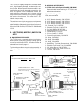
Figure 1 - PT-15XL Torch Front End Parts
ELECTRODE TIP (O )
20763 (Pkg. OF 4)
2
O NOZZLE ASS'Y
20751*
2
Oxygen Cutting Parts
TIP HOLDER (O ) - 20763
Includes O-Ring - 86W99
2
GAS SWIRL BAFFLE
(Ceramic) - 948142*
* See Table 1
For Options
Note:
All Set Screws Are Stainless Steel & Should Only
Be Replaced With Stainless Steel or Brass Screws.
NOZZLE RETAINING
CUP -20759
ELECTRODE TIP (N )
600236
2
View "A"
View "B"
TIP HOLDER
(N ) -2075343
Includes: O-Ring - 86W99
FRONT BODY
INSULATOR ASS'Y
20755
(Includes Items Marked•)
O-RING - 2064106•
(1-5/16" I.D.)
NOT SHOWN:
O-RING - 86W85• (1/2" I.D.)
(2) O-RING - 996526• (5/32" I.D.)
BODY ASS'Y - 20754
Pilot Arc Cable
& Connections
(See Fig. 4)
Hose &Cable
Connections
(See Fig. 3)
*GAS SWIRL
BAFFLE -2075341
(Poly)
NOZZLE ASS'Y -2075611
(Supplied) See Table 1
O-RING - 996527•
2
LOCATING PIN -
996242
O-RING - 996528•
CONTACT RING ASS'Y - 996341
Includes: Setscrew, No. 6-32 X 3/16 lg.(Cup Point)
Screw, No. 6-32 X 1/2" lg.

8
2. P/N 20813 Oxygen Kit contains the following PT-
15XL parts and tools:
4-0.098" Nozzle Assembly, P/N 21206B
8-Electrode Tip, P/N 20763
1-Electrode Tip Holder, P/N 20398
4-Gas Swirl Baffle, P/N 2075586
1-Nozzle Retaining Cup, P/N 20758
1-Insulator Body, P/N 20755
1-Pilot Arc Cable, P/N 20760
1-Contact Ring Assembly, P/N 996341
10-O-ring, P/N 86W85 .468 I.D.
20-O-ring, P/N 996526 .145 I.D.
10-O-ring, P/N 996527 1.30 I.D.
10-O-ring, P/N 996528 1.614 I.D.
1-Nozzle/Elec. Tip Holder Removal Tool, P/N 999630
1-Electrode Tip Removal Tool, P/N 996568
1-1/16" Allen Wrench, P/N 93750006
1-Silicone Grease (1 oz. tube), P/N 17672
1-Tool Box, P/N 950561
1-Retainer For Front Body Insulator P/N 33768
3.Reverse Swirl Nozzles and Gas Baffle
Standard swirl produces the least bevel on the right
hand side of the cut, as viewed in the direction of
travel. Sometimes, such as when mirror image cut-
ting, it is desirable for the square side to be on the left.
This requires the use of reverse swirl Nozzles and
Baffles. See Table 1 for P/N's. DO NOT mix standard
and reverse swirl parts on the same torch!
4. Oxygen and Beveling Nozzle Retaining Cup, P/N
20758 - Permits beveling up to 45
0
. Required for use
with Air Curtain or Bubble Muffler.
5. Corrosion Resistant Nozzle Retaining Cup P/N
21217. This cup has the same shape as the cup,P/N
20758 above but is insulated to reduce corrosion in
service with conductive cut water. This insulation
does not make it safe to touch the torch with the
power source on.
6. Two Piece O
2
Nozzle Assemblies: 21206B (STD) &
21207B (Rev.) These nozzles have a replaceable
ceramic insulator (P/N 21193).
III. FUME & NOISE REDUCTION
H
2
explosions can kill. H
2
explosions can result from
cutting underwater, especially when cutting active
metals such as aluminum or magnesium. See Form
14-373 (supplied with torch) or forms 12-528 or 15-
116 for more information.
A. Underwater cutting (N
2
ONLY)
1. Simply immersing the top of the workpiece under 2" to
3" of water markedly reduces fume and noise. Mate-
rials up to 1" thick can generally be cut underwater
with slight reductions in speed and quality.
2. Underwater cutting substantially reduces speed and
quality on thicker plates, especially aluminum. Cutting
plates thicker than 3 inches underwater is not recom-
mended.
3. Cutting underwater with Argon-Hydrogen is not rec-
ommended as explosive gas mixtures may collect in
the water table.
4. Underwater cutting with O
2
requires the use of a
Bubble Muffler or Air Curtain.
B. Air Curtain - The air curtain directs a flow of air around
the arc which permits underwater cutting with O
2
gas.
See Form 15-128 for details.
Standard Air Curtain Kit P/N 21385
Beveling Air Curtain Kit P/N 21404
C. Bubble Muffler - This device traps a bubble of air
around the arc using water recirculated from the water
table. This allows use of O
2
under water. The water
flow acts as a shield to block radiation and trap fumes
so that protection is also afforded when cutting above
water. See form 15-127 for details.
Bubble Muffler system P/N 2232615
D. Water Muffler - this device is used for suppression of
fume and noise when cutting with N
2
above water.
Contact your cutting machine representative for de-
tails.
IV. Maintenance (Refer to Figures 2 thru 5)
Electric Shock can kill.
Disconnect Power Source from incoming electrical
power before touching or servicing the torch. Metal
parts of the torch can be at high voltage.
Never use oil or grease on this torch. Handle parts
only with clean hands on a clean surface. Oil and
grease are easily ignited and burn violently in the
presence of oxygen under pressure. Use silicone
lubricant only where directed.
A. Removal & Replacement of Nozzle Assembly
1. Unscrew the nozzle retaining cup from the torch. If
the fine threads on the nozzle retaining cup and
torch body are dirty, clean and then spray the -
7. Retainer for Front Body Insulators: 33768, can be
used to prevent movement of front body insulator
when servicing torch.
WARNING
!
!
DANGER

9
more tha 0.030-in. Cracks in the insert are normal.
When using oxygen for cutting gas, replace elec-
trode tip (20763) if the hafnium insert is pitted more
than .090-in. or if a crater more than 0.120-in.
diameter has formed.
4. Check O-ring (86W99) inside tip holder periodi-
cally. If nicked, it should be replaced exercising
care to avoid scratching the O-ring groove. Lubri-
cate new O-ring lightly with silicone grease before
installing it into the tip holder.
5. Replace the gas swirl baffle if it is cracked or if the
front edge (nozzle seating surface) is chipped.
6. When reassembling slip the gas swirl baffle over
the electrode tip - tip holder assembly. Apply a light
coating of silicone grease (about 1/4-in. wide band)
just below the water exit holes and chamfer of the
tip holder. Then screw the electrode assembly into
the torch using 7/16" nut driver. Tighten firmly but
do NOT overtighten.
C. REPLACING THE INSULATOR BODY
The plastic insulator body (20755) should be removed
periodically and inspected for cracking and for possible
replacement of O-rings. To remove the insulator body,
do the following:
1. Remove nozzle retaining cup, nozzle assembly,
electrode tip, tip holder, and gas swirl baffle as
described previously.
2. Pull the insulator body straight out.
NOTE: The pilot arc cable will be attached, so allow
plenty of slack.
3. Lubricate the O-rings lightly with silicone grease. If
necessary, replace O-rings.
4. If replacing the insulator body, disconnected the
pilot arc cable by loosening the setscrew with the
1/16: Allen wrench (supplied with torch) at the
contact right assembly (996341). Remove contact
ring assembly from the insulator body by removing
one socket head screw with a 7/64" Allen wrench
(not supplied).
5. Reassemble in reverse order. Align insulator body
with locating pin (996242) and push in.
FRONT END
(See Table 1)
NOTE
For Service Lines Supplied
(See Figure 3)
SLEEVE - 19483
CLAMP INSULATOR BUSHING - 996342
CLAMP - 996565
BOOT HOSE - 996647
B. REPLACING ELECTRODE AND GAS SWIRL BAFFLE
1. Remove retaining cup and nozzle assembly as de-
scribed above in Sect. IV-A. Front insulator retainer
P/N 33768 may be installed to prevent movement of
front insulator body.
2. Remove electrode by using the 7/16" nut driver
(996568) supplied with the torch). If electrode holder
did not come out with the electrode, then remove it by
using removal tool (999630) supplied with the torch.
The lugs will engage with the slots on the top holder.
To avoid damaging the gas baffle when removing or
reassembling the electrode, hold the nut driver or
removal tool straight.
The gas swirl baffle should come out with the elec-
trode holder. If it does not, remove by using one
finger.
3. If using nitrogen or H-35 for cutting gas, replace
electrode (600236) if the tungsten insert is pitted
threads with a commercially available silicone spray
to prevent thread damage or cross-threading during
reassembly.
2. To remove the nozzle assembly, grip the nozzle
assembly with the slotted tubular tool (999630 -
supplied with the torch) and pull straight out.
3. Apply a very light coating of silicone grease (17662,
1 oz. tube) around the outer periphery of the copper
body on the nozzle assembly. (This will lubricate the
O-ring in the torch body when inserting the nozzle
assembly.) Make sure the silicone rubber gasket is
set evenly around the shoulder of the ceramic nozzle
insulator on the nozzle assembly. Handle the nozzle
assembly carefully to avoid breaking the insulator.
4. Place the nozzle assembly inside the retaining cup by
locating the ceramic insulator through the hole of the
retaining cup.
5. Carefully assemble the retaining cup onto the torch
and tighten slowly until HAND TIGHT. The nozzle
assembly will seat against the gas swirl baffle. Do
NOT over-tighten. (Holes in the plastic gas swirl
baffle may squeeze close and restrict the gas flow,
ceramic baffles may break. Improper seating or a
poor gasket will be revealed by an uneven cutting
water spray once the torch is set up.)
Dimensions & Weight
Length 15-1/2-in.
Diameter 2-in.
Diam of Ins. Bushing 2-1/4-in.
Weight (Less Service Lines) 3.5 lbs.
Shipping Weight 16 lbs.
Supplied:
Nozzle & Electrode Tip Removal Tool - 999630
Electrode Tip Removal Tool - (7/16" Nut Driver) - 996568
1/16" Allen Wrench - 93750006
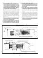
Figure 2 - PT-15XL Plasma Arc Cutting Torch Assembly

10
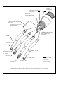
Figure 3 - PT-15XL Hose and Cable Assemblies (supplied with torch) and Connections
WATER OUT
CABLE CONNECTION
7/16 X 20 R.H.
"CUT WATER" INJECTION
HOSE CONNECTION
7/16 X 20 R.H.
GAS HOSE
CONNECTION
3/8 X 24 R.H.
POWER CABLE (6')
996248*
7/16 X 20 L.H.
7/16 X 20 R.H.
POWER CABLE (6')
996248*
COOLING WATER INJECTION
HOSE CONNECTION
7/16 X 20 L.H.
WATER INJECTION
HOSE ASS'Y
(6') - 996250
5/18 X 18 R.H.
GAS HOSE ASS'Y
(6') - 996249
5/18 X 18 R.H.
* Note That 996248 Power Cables have 7/16 X 20 R.H. Thread At One End, 7/16 X 20 L.H. At The Other.
NOTE - 6 ft. Cables
and Hoses for 20762
Torch Shown.
Refer to Tables on
Page 11 For Other
Lengths.
PILOT ARC CABLE (8') - 20760
Not Shown:
CONNECTOR - 20408
(2) SETSCREW - #6-32 X 1/4"
INSULATOR - 20409

11
SOCKET HEAD SCREW
Remove to Release Contact Ring
Use 7/16" Allen Wrench (Not Supplied)
INSULATOR BODY
SEE
VIEW "A"
VIEW "A"
(2) O-RING - 951000
.176 ID X .050W
CONTACT RING ASS'Y
996341
PILOT ARC CABLE SET SCREW
Remove to Release Pilot Arc Cable
Use 1/16" Allen Wrench (Supplied with torch)
CONNECTOR, HI-FREQ. - 20408
fully remove the deposits using a small brush or drill
bit. If using a drill bit, insert carefully and push it
back and forth. Do NOT twist the drill bit.
5. To reassemble the nozzle assembly, snap the
centering sleeve onto the copper nozzle body
(bevel facing away from body). Insert the nylon
spacer.
6. Oxygen nozzles P/N's 20751 & 20920 are one
piece nozzles and do not come apart. They must
be replaced as complete units.
7. Two piece oxygen nozzles P/N's 21206B & 21207B
have a replaceable ceramic insulator P/N 21193.
Pry along the outside of the white ceramic to
remove it.
To install a new insulator, lubricate the red o-ring
with silicone grease and push the insulator on with
a twisting motion.
2
HI-FREQ.
CONNECTOR INSULATOR - 20409
P.A. BUS INSULATOR - 20403
PILOT ARC CABLE ASSEMBLY
(4) SCREW - #6/32 X 1/8
Figure 4 - PT-15XL Pilot Arc Cable Assembly
Pilot
Arc Cable
D. INSPECTION & DISASSEMBLY OF NOZZLES
1. Check the copper nozzle for melting from excessive
current, gouges from internal arcing, tungsten par-
ticles in the throat, or nicks and deep scratches on
the outer O-ring sealing surface. If any of these
defects are visible, replace the nozzle assembly.
White Hf-O deposits are normal in O nozzles.
2. To disassemble an XR nozzle assembly, pry off the
centering sleeve (996618) using a small screw-
driver between the sleeve and nozzle body. Re-
place the parts shown in figure 2 if necessary.
3. Replace the ceramic insulator if it is cracked. Check
the orifice diameter of the replacement insulator. It
should be 0.015 to 0.030-in. larger than the nozzle
body orifice. (See Table in Figure 2.)
4. In some locations, deposits left by evaporated hard
water may build up on the nozzle orifice tip Care-

12
8. Cleaning of oxygen nozzles:
As the electrode wears considerable deposits of
hafnium oxide and silver can build up in the nozzle.
Calcium carbonate can build up at the nozzle exit
if the cut water is not adequately treated. These
deposits sometimes cause substantial reductions
in cut quality, speed, and consumable life.
Nozzle performance can be restored by removing
these deposits from the inside of the nozzle and the
nozzle exit. A twisted piece of sandpaper or crocus
cloth usually cleans the nozzle well enough. Care
must be taken not to damage the thin copper edge
at the nozzle exit. The 340 AMP nozzles P/Ns
35664 & 35665 have a heavier, less easily dam-
aged exit as compared to the 260 AMP and 300
AMP nozzles.
Note that nozzle performance is also degraded by
nicks or elongation of the orifice due to double arcs
or mechanical damage. Cleaning will not restore
performance to a damaged nozzle.
Whenever a nozzle is removed for cleaning the
electrode should be inspected. If wear is greater
than .090 inches or very irregular the electrode
should be replaced.
E. REPLACING CABLES AND HOSES
1. To disconnect the two power cables, water injection
hose, and the gas hose at the back end of the torch,
unscrew the plastic sleeve (19483) from the stain-
less steel body.
2. Pilot arc cable (20760) is attached to a connector
(20408) under insulator tubing (20409). Loosen set
screw with 7/62" Allen wrench to remove cable
from connector. A 12-in. long 14 ga. copper wire is
connected to the contact ring assembly and to this
connector.
3. Straighten out all cables and hoses and make sure
the torch sleeve is straight when screwing it back
onto the torch body. Threads are rather fine and
easy to cross thread. Do not force the sleeve. A little
bit of silicone grease will help.
4. Make sure the boot hose (996647) is secured to
protect the service lines from arc radiation when
the torch is ready to operate, make sure the service
lines are well out of the way.
BACK OF SLEEVE - 19483
5 inches
5 inches
15 turns of tape to form barrier to slipage of braid.
BRAIDED SHIELD - 72020003
BOOT
Braid is taped in place, then folded back and taped again.
BACK OF SLEEVE - 19483
2
inches
4 1/4
inches
3
inches
SLEEVING
BOOT
NOTE: Braid does not go over Gas or Cut Water Hoses
Securely tape around hose bundle 2" wide.
Slide braid down and tape over 4-1/4".
PCM-8 Style Cable Bundle
ESP-1000 Style Cable Bundle
Figure 5 - PT-15XL Cable and Hose Assembly

13
PT-15XL 8ft. For PCM-8 P/N 602711 Part No.
Power Cable (2) Required
Gas Hose
Water Injection Hose
Pilot Arc Cable
996248
34360
34354
34357
PT-15XL 6ft. P/N 21304 Part No.
Power Cable (2) Required
Gas Hose
Water Injection Hose
Pilot Arc Cable
34363
34361
34355
34358
PT-15XL 12ft. P/N 21305 Part No.
Power Cable (2) Required
Gas Hose
Water Injection Hose
Pilot Arc Cable
34364
34362
34356
34359
PT-15XL 17ft. P/N 21306 Part No.
Power Cable (2) Required
Gas Hose
Water Injection Hose
Pilot Arc Cable
34775
34776
34777
34778
PT-15XL 4-1/2ft. P/N 21307 Part No.
Power Cable (2) Required
Gas Hose
Water Injection Hose
Pilot Arc Cable
21267
21261
21258
21264
PT-15XL 20ft. P/N 21302 Part No.
Power Cable (2) Required
Gas Hose
Water Injection Hose
Pilot Arc Cable
21268
21262
21259
21265
PT-15XL 25ft. P/N 21303 Part No.
Power Cable (2) Required
Gas Hose
Water Injection Hose
Pilot Arc Cable
21266
21260
21257
21263
PT-15XL 15ft. P/N 21301 Part No.
Power Cable (2) Required
Gas Hose
Water Injection Hose
Pilot Arc Cable
996248
996249
996250
20760
PT-15XL 6ft. For PCM-8 P/N 20762 Part No.
Power Cable (2) Required
Gas Hose
Water Injection Hose
Pilot Arc Cable
602712
602713
602714
602715
PT-15XL Cables and Hoses, Parts Information

14
F-15-031-B 7/95 5C
ESAB
ESAB Welding & Cutting Products
PO Box 100545, Florence SC 29501-0545
-
 1
1
-
 2
2
-
 3
3
-
 4
4
-
 5
5
-
 6
6
-
 7
7
-
 8
8
-
 9
9
-
 10
10
-
 11
11
-
 12
12
-
 13
13
-
 14
14


ESAB PT-15XL Plasmarc Cutting Torch User manual
- Category
- Welding System
- Type
- User manual
Ask a question and I''ll find the answer in the document
Finding information in a document is now easier with AI
Related papers
-
ESAB PT-15XL Plasmarc Water Injection Cutting Torch Installation guide
-
-
-
-
-
ESAB ESP-1000 Plasmarc System User manual
-
-
-
-
Other documents
-
 Sunjoy 110109011 Installation guide
-
Shimano BL-M315 Exploded View
-
Trust 20403 Datasheet
-
König & Meyer 21404-000-55 Datasheet
-
TOA BP-031B TET Specification Data
-
Kramer VA-15xl User manual
-
Shimano BL-M396 Exploded View
-
Faber-Castell 6300000 Operating instructions
-
-
Garmin GPS 15xH/15xL Owner's manual
