MUELLER
®
Centurion
®
Series Fire Hydrant
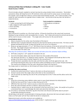
Lubrication and Maintenance
Remove Oil Filler Plug and check oil
level. Oil should be level with Oil Filler
Plug Hole.
Ifoilislow,useasmallfunneltoadd
MUELLER Hydrant Lubricant.
WhenoilislevelwithOilllerPlug
Hole,replaceOilFillerPlug.
1. 2.
3.
CAUTION: Always ll the oil reservoir with the Bonnet installed, the Hydrant in its normal upright position, and
the main valve fully closed. If the Hydrant is lled with lubricant under any other circumstances, excess lubricate can
overll the Bonnet and create a pressure lock. This could result in damage to the seals or Bonnet or prevent proper
Hydrant operation.
• Drains are clogged by some foreign
material.
• Failure to leave Cap off of Hydrant
to allow air to enter so Barrel will
drain.
The foregoing procedure introduces
full line pressure to Drain Valves.
It provides the best method for
cleaning Drain Valves using water
pressure.
IMPORTANT - Initial installation
of Hydrant MUST BE MADE
PROPERLY so Trafc Flange will
function properly. Hydrant should
be blocked at ground line and
around Shoe using concrete or
similar substance to prevent ground
from giving way when Hydrant is
struck (see page 9-10).
For additional information on Hydrant
anchorage,blocking,anddrainage,
seeAWWAStandardC600and
ManualM17.
1. To ensure their readiness for
immediateuse,itisrecommended
that Fire Hydrants be inspected and
tested at six-month intervals.
2. Inspect visually for damaged or
missing parts.
3. Remove Oil Filler Plug to check
oillevel.Ifoillevelislow,llas
shown above. Loosen one Nozzle
Cap slightly and tighten the others.
Open Hydrant fully. Tighten loose
Nozzle Cap when water starts to
ow.Checkallangeconnections
for leaks. Turn Operating Nut to fully
CLOSED position.
4. IfwateroroiloverowsfromOil
FillerHole,removeBonnetand
replace O-rings in both the Bonnet
and the Hold-Down Nut. Inspect
andcleanStem,andreplaceitif
corroded or pitted. Check oil level.
Replace Bonnet and test for leaks.
5. Use A-367 Brass Sleeve when
re moving or replacing Bonnet
or Hydrant Barrel to protect stem
O-rings.
6. RemoveoneNozzleCap,stand
on the side of Hydrant opposite the
capremoved,openHydrantfully,
andushBarrelandHydrantLateral.
Turn Operating Nut to fully CLOSED
position.
7. Remove all Nozzle Caps. Clean
and lubricate threads.
8. Examine inside of Barrel to make
certain Drain Valves have completely
drained water from Barrel. If water
failstodrainfromBarrel,itmay
be caused by one or more of the
following conditions:
• Water Table in ground is higher
than Drains.
• WhenHydrantwasinstalled,
coarse gravel was not placed
around Drains.
!
!
8
EQUIPMENT & TOOLS NEEDED –PPE:Safetyshoes,safetyvest,safetyglasses,workgloves.
Tools:
1
/4”hex-headwrench,A-51lubricatingoil,A-311operatingwrench,A-367brasssleeve.
9
MAINTENANCE