SpeedyBee F405 V3 BLS 50A 30×30 Stack for FPV Drones User manual

Type
User manual
F405 V3
BLS 50A 30x30
F405 V3 BLS 50A 30x30 Stack
User Manual V1.0
(Click on any section to jump)
Contents
Pa 1 - OverView
Specs Oveiew
Dimensions
Package
FC & ESC Connection
Pa 2 - SpeedyBee F405 V3 Flight Controller
Layout
FCs Peripheral Connection
App & FC Conguration
FC Firmware Update
Specications
Pa 3 - SpeedyBee BLS 50A 4-in-1 ESC
Layout
Connection with Motors & Power Cable
ESC Conguration
ESC Firmware Update
Specications
2
1
3
4
5
6
7
8
9
10
11
12
13
14
Product Name
Flight Controller
ESC
Bluetooth
Wireless FC Firmware Flashing
Power Input
Mounting
Dimension
Weight
SpeedyBee F405 V3 BLS 50A 30x30 Stack
SpeedyBee F405 V3
SpeedyBee BLS 50A 4-in-1 ESC
Suppoed. For FC & ESC parameter settings
NOT Suppoed
3-6S LiPo
30.5 x 30.5mm(4mm hole size )
45.6mm(L) x 44mm(W) x 18.3mm(H)
23.4g
Pa 1 - OverView
1/14
Specs Oveiew
Wireless Blackbox
Dwonload & Analysis NOT Suppoed
2/14
Dimensions
30.5mm
44mm39.4mm
16.1mm
1.6mm 1.6mm
6.1mm7.8mm
45.6mm
41.6mm
30.5mm
4mm4mm
Package 3/14
Option 2 - SpeedyBee F405 V3 Flight Controller
SpeedyBee F405 V3 Flight Controller x 1
SpeedyBee BLS 50A 4-in-1 ESC x 1
35V 1000uF Low ESR Capacitor x 1
M3 Nylon Nut x 5
M3 silicone O Ring x 5
M3*8mm Silicone Grommets(for FC) x 5
M3*8.1mm Silicone Grommets(for ESC) x 5
SH 1.0mm 15mm-length 8pin Cable(for FC-ESC connection) x 1
M3*30mm Iner-hexagon Screws x 5
DJI 6pin Cable(80mm) x 1
XT60 Power Cable(70mm) x 1
1
2
3
4
5
6
7
8
9
10
11
1
2
Option 1 - SpeedyBee F405 V3 50A 30x30 Stack
SpeedyBee BLS 50A 4-in-1 ESC x 1
35V 1000uF Low ESR Capacitor x 1
M3 silicone O Ring x 5
XT60 Power Cable(70mm) x 1
SH 1.0mm 30mm-length 8pin Cable(for FC-ESC connection) x 1
M3*8.1mm Silicone Grommets(for ESC) x 5
1
2
3
4
5
6
Option 3 - SpeedyBee BLS 50A 4-in-1 ESC
3 9 11
4
5
610
7
8
1 2
3
4
6
5
SpeedyBee F405 V3 Flight Controller x 1
M3*8mm Silicone Grommets(for FC) x 5
SH 1.0mm 30mm-length 8pin Cable(for FC-ESC connection) x 1
DJI 6pin Cable(80mm) x 1
1
2
3
4
1
3
2 4
FC & ESC Connection 4/14
Method 1 - Using 8-pin cable
Use the 8-pin cable in the package to connect the FC and the ESC.
Or solder 8 wires directly to the 8 pads on each end.
Use any end of the 8-pin JST cable to connect the FC to the ESC.
Solder 8 wires to the 8 pads on each end referring to the
pad denition below.
Method 2 - Direct soldering
BTA
GND
M2
M3
M4
CUR
TEL
M1
VBTA
GND
S2
S3
S4
CURRENT
N/A
S1
F405 V3 Flight Controller BLS 50A 4-in-1 ESC
BLS 50A 4-in-1 ESC
F7 V3 Flight Controller
Pa 2 - F405 V3 Flight Controller
5/14
Layout
LED Indicator Denition
RED LED - Power Indicator.Solid Red after powering up.
GREEN LED - Bluetooth status light. Solid Green indicates Bluetooth is connected.
BLUE LED - Flight controller status light which is controlled by the ight controller rmware.
[A]Only if the ight controller gets bricked and can’t power up, please follow these
steps to re-ash rmware for it:
Inse a USB A to TYPE-C cable to your PC.
Press and hold the BOOT button, inse the USB cable into the ight controller,
then release the BOOT button.
Open Betaight/Emuight/INAV congurator on the PC, go to the ‘Firmware Flashing’
page, choose the target ‘SPEEDYBEEF405V3’ and ash.
[B]. When the FC is powered on and in standby mode, the BOOT button can be used to
controller the LED strips connected to LED1-LED4 pads on the corners. By default,
sho-press the BOOT button to cycle the LED displaying mode. Long-press the
BOOT button to switch between SpeedyBee-LED mode and BF-LED mode.
Under BF-LED mode, all the LED1-LED4 strips will be controlled by the Betaight rmware.
Long press the button for 3 seconds to switch the control modes between BF_LED
mode and SB_LED mode.
BOOT Button
USB TYPC-C Po
VTX(Analog/DJI)Betaight LEDGPS&Compass
OSD Chip(AT7456E) Gyro(BMI270)
Red LED
Green LED
Buzzer
Blue LED
ReceiverFor Second 4-in-1 ESCFPV Cam
9V 2A BEC
5V 2A BEC
8pin Connector(to ESC)
BOOT Button
Antenna
Bluetooth Chip
Orange LED
4-level LED
batte indicator
MCU: F405
Extra PWM output
SD Card Slot
(Use SDSC/SDHC cards,
format to 'FAT32' format)
DJI Air Unit Connector
TVS Diode
(Anti-volatge spike)
Barometer
LED1
LED2 LED3
LED4
Orange LED - LED Control Mode Indicator. It indicates the 4 sets of LED strips connected
to LED1-LED4 pads on the corners of the ight controller are controlled by Betaight
rmware(BF_LED mode) or the Bluetooth chip(SB_LED mode).
Solid Orange :tindicates the 4 x LEDs are in SB_LED mode. In this mode, when the FC is
powered on and in standby mode, press the BOOT button to cycle the display modes
of the LEDs. You could also change modes in the app wirelessly.
OFF :indicates the 4 x LEDs are controlled by Betaight rmware.
CH2 RX
CH1 TX
5V
GND
6/14
FCs Peripheral Connection
Model: Phoenix 2
Joshua Edition
Model: Phoenix 2
5V
GND
VIDEO
IRC
PGND
3.7-5V
5-36V
GND
Video
Menu
BZ-
BZ+
7.4-26.4V
GND
RX
Video
GND
5V
5V
TX
GND
GND
CH2
CH1
GND
GND
5V
GND
LED
SDA
SCL
TX
RX
GND
5V
SDA
SCL
R6
T6
G
4V5
G
VTX
9V
T1
R1
SBUS
IRC
SBUS
RX
TX
5V
G
NC
S
5V
GND
CAM
CC
DIN
DIN
DIN
SBUS
G
SIGNAL
5V
5V
S9
G
G
5V
SBUS
5V
5V
5V
T2
R2
TX
5V
G
RX
T2
GND
GND
PPM
3V3
3V3
7/14
App & FC Conguration
Search ‘SpeedyBee’ on Google Play or App Store. Or download the Android .apk le
on our website: https://www.speedybee.com/download.
Get the SpeedyBee App
FC Conguration
1
3
2
8/14
FC Firmware Update
SpeedyBee F405 V3 ight controller does not suppo wireless rmware ashing,
so please ash rmware for it on your PC following the steps below:
Connect the ight controller to the PC with a USB cable
Open Betaght/Emuight/INAV congurator on your PC. Take Betaight
congurator as an example, go to the ‘Firmware Flashing’ page, choose the target
SPEEDYBEEF405V3’ and ash.
9/14
Specications
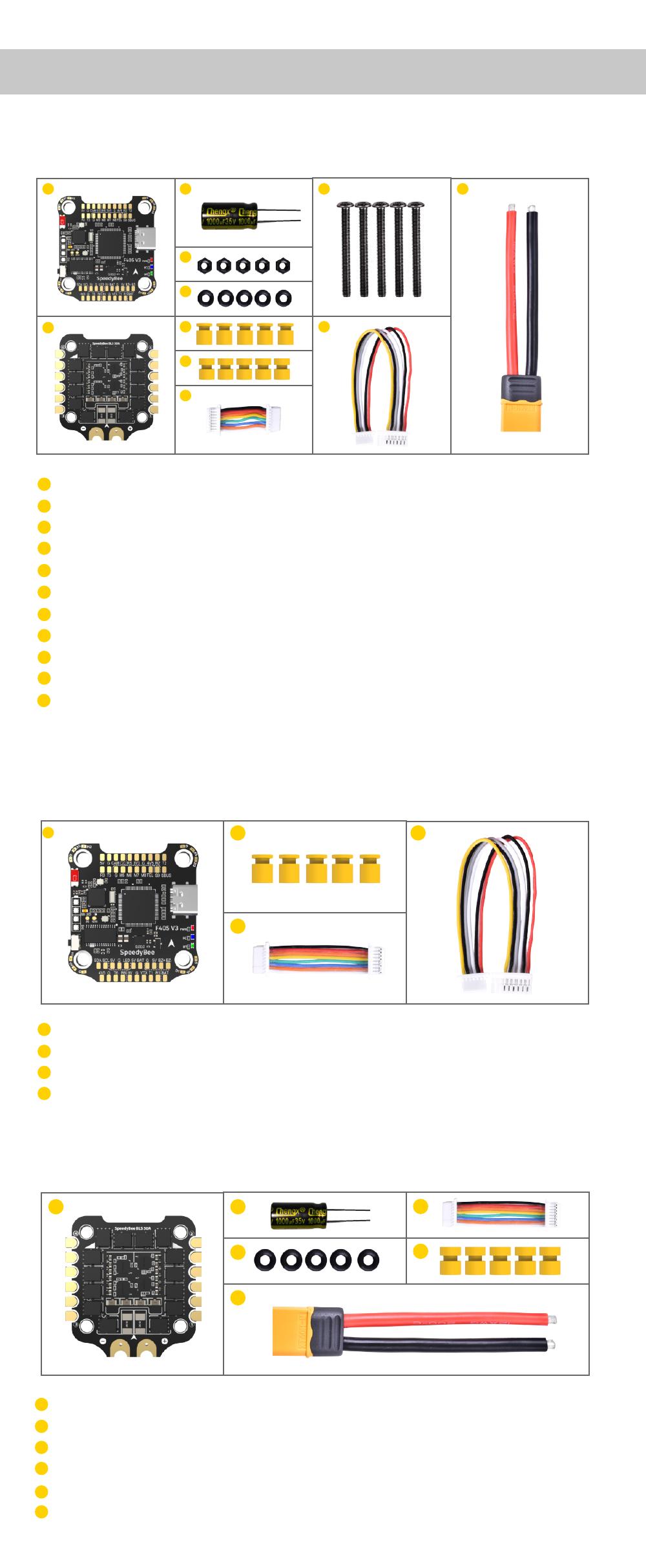
Product Name SpeedyBee F405 V3 30x30 Flight Controller
MCU STM32F405
IMU(Gyro) BMI270
USB Port Type Type-C
Barometer Built-in
OSD Chip AT7456E chip
BLE Bluetooth Supported. Used for Flight Controller configuration
(MSP should be enabled with Baud rate 115200 on UART 4)
DJI Air Unit Connection Way Two ways supported: 6-pin connector or direct soldering.
Blackbox MicroSD Card Slot
Supported. Please use ≤4GB SDSC/SDHC microSD card and should be formatted to
6-pin DJI Air Unit Plug Supported. Completely compatible with DJI O3/RunCam Link/Caddx Vista/
DJI Air Unit V1, no wire is needed to be changed.
FAT16/FAT32 format. Don't use SDXC cards. Note: Betaflight can only recognize
4GB max.
BetaFlight Camera Control Pad Yes(CC pad on the front side)
Current Sensor Input Supported. For SpeedyBee BLS 50A ESC, please set scale = 386 and Offset = 0.
Power Input 3S - 6S Lipo(Through G, BAT pins/pads from the 8-pin connector or 8-pads on the
bottom side)
5V Output 9 groups of 5V output, four +5V pads and 1 BZ+ pad( used for Buzzer) on front side,
and 4x LED 5V pads. The total current load is 2A.
9V Output 2 groups of 9V output, one +9V pad on front side and other included in a connector
on bottom side. The total current load is 2A.
3.3V Output Supported. Designed for 3.3V-input receivers. Up to 500mA current load.
4.5V Output Supported. Designed for receiver and GPS module even when the FC is powered
through the USB port. Up to 1A current load.
ESC Signal M1 - M4 on bottom side and M5-M8 on front side.
UART 6 sets(UART1, UART2, UART3, UART4(Dedicated for Bluetooth connection),
UART5(Dedicated for ESC telemetry), UART6)
ESC Telemetry UART R5(UART5)
I2C Supported. SDA & SCL pads on front side. Used for magnetometer, sonar, etc.
Traditional Betaflight LED Pad Supported. 5V, G and LED pads on bottom of the front side. Used for WS2812 LED
controlled by Betaflight firmware.
Buzzer BZ+ and BZ- pad used for 5V Buzzer
BOOT Button
Supported.
[A]. Press and hold BOOT button and power the FC on at the same time will force the
FC to enter DFU mode, this is for firmware flashing when the FC gets bricked.
[B]. When the FC is powered on and in standby mode, the BOOT button can be used
to controller the LED strips connected to LED1-LED4 connectors on the bottom side.
By default, short-press the BOOT button to cycle the LED displaying mode. Long-
press the BOOT button to switch between SpeedyBee-LED mode and BF-LED
mode. Under BF-LED mode, all the LED1-LED4 strips will be controlled by Betaflight
firmware.
RSSI Input Supported. Named as RS on the front side.
Smart Port / F.Port Not supported
Supported Flight Controller
Firmware BetaFlight(Default), EMUFlight, INAV
Firmware Target Name SPEEDYBEEF405V3
Mounting 30.5 x 30.5mm( 4mm hole diameter)
Dimension 41.6(L) x 39.4(W) x 7.8(H)mm
Weight 9.6g
Pa 3 - SpeedyBee BLS 50A 4-in-1 ESC
10/14
Layout
MOTOR 2
MOTOR 1
MOTOR 3
MOTOR 4
Capacitor pin
hole(GND) Capacitor pin
hole(BAT+)
8pin connector(to FC)
TVS Diode
BAT+BAT-
Driver chips
MCU(BB21)
11/14
Connection with Motors & Power Cable
Note: In order to prevent the stack from being burnt out by voltage spikes
on powering up, it is strongly recommended to use the Low ESR capacitor in
the package.
Motor 4
Motor 3
Motor 2
Motor 1
XT60 Power Cable
1000uF Low ESR
Capacitor
12/14
ESC Conguration
If you’d like to use a PC congurator, we recommend the ESC Congurator.
1
2
3
4
13/14
ESC Firmware Update
You could ash both BLHeli_S and Blue Jay rmware for this ESC.
You need to pulg in the batte to the F405 V3 and then connect a USB
cable between the F405 V3 and your PC. Then ash ESC rmware
(BLHeli_S or Blue Jay) in the following online congurator:
https://esc-configurator.com/
Note: ESC Type should be set as 'J-H-50'.
4
5
6
1
2
3
5
5
5
14/14
Specications
Product Name SpeedyBee BLS 50A 30x30 4-in-1 ESC
Firmware BLHeli_S JH50
Wireless Configuration Full Configuration Supported in the SpeedyBee app
PC Configurator Download Link https://esc-configurator.com/
Continuous Current 50A * 4
Burst Current 55A(5S)
TVS Protective diode Yes
External Capacitor 1000uF Low ESR Capacitor(In the package)
ESC Protocol DSHOT300/600
Power Input 3-6S LiPo
Power Output VBAT
Current Sensor Support (Scale=386 Offset=0)
Mounting 30.5 x 30.5mm( 4mm hole diameter)
Dimension 45.6(L) * 44(W) * 6.1mm(H)
Weight 13.8g
  • Page 1 1
  • Page 2 2
  • Page 3 3
  • Page 4 4
  • Page 5 5
  • Page 6 6
  • Page 7 7
  • Page 8 8
  • Page 9 9
  • Page 10 10
  • Page 11 11
  • Page 12 12
  • Page 13 13
  • Page 14 14
  • Page 15 15

SpeedyBee F405 V3 BLS 50A 30×30 Stack for FPV Drones User manual

Type
User manual

Ask a question and I''ll find the answer in the document

Finding information in a document is now easier with AI