Page is loading ...

1
AMETEK Programmable Power’s two new series of multiple-
output DC programmable power supplies are designed to
address the needs of a wide range of applications, such as
military and aerospace test, printed circuit board assembly
(PCBA) test, automotive test, telecommunications test,
semiconductor test, and process-control applications. The
new products include the Sorensen™ Asterion® DC ASA and
Sorensen™ Asterion® DC ASM Series, which fit in a 1U-high
chassis and provide as many as three independent isolated
outputs. The 1U form factor saves space in ATE applications,
while the multiple voltages support applications such as
functional PCBA test as well as burn-in and environmental test.
Application Note
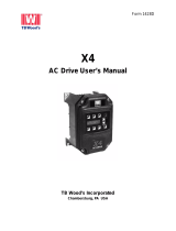
The Asterion DC ASA Series features autoranging outputs
in which maximum output voltage varies inversely with
maximum output current to maintain a constant-power
characteristic. The autoranging feature provides maximum
flexibility for ATE systems, in which your required maximum
voltage and current ratings may change with successive types
of devices under test. The four available output channels in
the ASA Series follow a 600W I-V curve, with maximum ratings
per channel of 60V at 42A, 80V at 22A, 200V at 17A, or 400V
at 6A, with the three-output supply offering 1,800W total
output power (Figure 1).
Multiple-Output DC Supplies
Combine Flexibility and
Power Density
Figure 1. The ASA Series includes four models that follow a 600W I-V curve per channel.

In contrast, the Asterion DC ASM Series features three
independent, isolated rectangular output channels. However,
the ASM Series does offer higher power ratings at 1,700W
per channel for a total output of 5,100W for a three-channel
supply in a 1U chassis. The ASM Series has eight channel
configurations offering fixed voltage and current ratings
ranging from 40V at 42A to 400V at 4.3A (Figure 2).
Specific Applications
Specific customers using the new supplies include a prime
contractor who was awarded an Air Force engineering and
manufacturing development contract for a new long-range
missile system. Over the course of the multi-year, billion-dollar-
plus contract, the customer will require a variety of AC and
DC Asterion programmable power supplies. The customer has
already purchased several Asterion supplies, including models
in the ASA Series. Key selling points included the ability to
combine two ASA units to provide six isolated supplies in a 2U
rack height, providing considerable space savings in its test
systems. In addition, the customer cited AMETEK Programmable
Power’s reputation for long-term support. The customer
also noted that the Asterion line is in the early stages of its
lifecycle, whereas competitors are offering legacy models that
are nearing end of life. The customer plans to purchase more
Asterion supplies over the life of its Air Force contract.
Another customer in the aerospace industry purchased several
ASA models after evaluating a demonstration unit and close
consultation with AMETEK Programmable Power’s sales and
applications teams. The customer will use the supplies in new
automated test systems. The customer cited the ability to fit
the six supply channels required for each test system into a 2U
rack height. This customer also noted that the ASA is at the
early stages of its lifecycle and that AMETEK Programmable
Power has a history of years of comprehensive support. The
customer has also added the ASA Series to their common
acquisition list to support global locations.
Local and Remote Control
Customers can take advantage of many features of the ASA
and ASM Series to optimize their applications for either
local or remote control. For local operation, a front-panel
touchscreen and an encoder selector button allow users to
control output parameters, measurements, configurations,
and system settings (Figure 3).
2
858.450.0085 | ProgrammablePower.com
From the home screen, you can navigate to several top-level
menus. Dashboard, for example, allows you to change output
parameters and view output measurements for each channel
(Figure 4).
The Output Program menu provides for the setting of
voltage, current, power, regulation mode, output state, and
overvoltage-protection (OVP) level for each channel, while
the Measurement menu provides the current values of those
parameters, states, and modes for each channel. Other top-
level menus include Configuration, which provides for the
setup of power-on states and user V/I limits; and System
Settings, which displays firmware versions and last calibration
date and controls display brightness and timeout. The front
panel also includes LEDs that indicate each channel’s on/off
status and signal internal fault conditions that result in supply
output shutdown.
Yet another front-panel LED indicates when the supply is under
analog or digital remote control via rear-panel connections
(Figure 5). You can set up the remote interfaces using the
Control Interface top-level menu, which lets you choose which
interface to use and allows you to enter relevant settings.
If you are using the optional isolated analog programming
interfaces, the Control Interface menu allows you to specify
whether you are using a voltage or resistance source, and
you can choose full-scale voltage from 5V to 10V or full-
scale resistance from 5kΩ to 10kΩ. The analog interface also
provides monitor signals, with the default values of 0V to
10V corresponding to 0% to 100% of full-scale output
voltage and current.
Voltage (V) Current (A) Power (W)
40 42 1680
60 28 1680
80 22 1700
100 17 1700
150 12 1700
200 9 1700
300 6 1700
400 4.3 1700
Figure 2. ASM Series are available in eight configurations offering
fixed voltage and current ratings.
Figure 3. The ASA (pictured) and ASM Series include a
touchscreen, rotary encoder, and LEDs.
Figure 4. This Dashboard top-level menu shows parameters for each
channel with channel 1 highlighted.
Figure 5. The ASA (pictured) and ASM Series rear panel provides
access to analog and digital interfaces.

3
Digital interfaces include LAN, RS-232C, and USB 2.0 with an
IEEE-488 interface optional. For RS-232C, for example, you can
use the Control Interface menu to set baud rate, number of
bits, number of stop bits, and parity. If you choose LAN, you
can access settings such as IP address and gateway address
and specify whether to enable Dynamic Host Configuration
Protocol (DHCP) using the Control Interface menu (Figure 6).
For USB, you can use the Control Interface menu view the
configured baud rate, and for GPIB, you can set the IEEE-
488 address and specify whether the supply should send a
power-on service request to the host computer. Once a digital
interface is set up, users can control outputs and settings
remotely on a computer screen via the Asterion DC Virtual
Panels™ GUI.
Programmable functions for the ASA and ASM Series include
on/off delays, voltage and current ramps, and sequencing.
On/off delays are useful for devices under test such as PCBAs
that require multiple voltage sources that turn on and off at
different times. ASA and ASM models support delays from
0.1s to 100s, which are programmable via the Configure
Delay top-level menu or by remote control.
Voltage and current ramps are programmable with dwell
times from 1ms to 9,999s. You can program them via the
Ramp top-level menu or remotely. The Virtual Panel segment
shown in Figure 7 shows channel 1 programmed to ramp
from 0V to 32V in 12s in response to a hardware trigger and
channel 2 programmed to ramp from 0V to 180V in 15s in
response to a software trigger.
Figure 6. The Control Interface provides access to LAN settings.
Figure 7. This segment of a Virtual Panels display shows ramp
programming for channels 1 and 2.
Sequencing
If you are using a remote digital interface, you have access
to sequencing, which is not supported from the front panel.
The ASA and ASM Series can store 50 sequences of up to 20
commands each. Sequences can be made up of an extensive
list of step and ramp functions as well as looping and go-to
commands. One sequence may call another as a subroutine.
Consider this SCPI code segment for a sequence named
SEQ1 (other necessary commands such as reset and memory
allocation are omitted here for brevity):
Figure 8 shows the output characteristic resulting from this
sequence. After the STOP command, the unit remains at the
state set by the last command within the sequence.
Now consider this segment of a second sequence named SEQ2:
Figure 9 shows the output characteristic resulting from
this sequence. Note that this segment ends with a RETURN
command instead of STOP. If SEQ2 runs directly, RETURN acts
as a STOP command. However, if SEQ2 runs as a subroutine,
the RETURN command returns control to the calling sequence.
Figure 8. The sample code segment named SEQ1 generates this response.
PROG<n>:DEF 1, VIMODE,3,4,11,10 //go to 3V, 4A with 11V OVP for 10s
PROG<n>:DEF 2, RAMPTOV,3,5,4,11,10 //ramp from 3V to 5V in 10s.
PROG<n>:DEF 3, VIMODE,5,4,11,10 //hold 5V for 10s
PROG<n>:DEF 4, RAMPTOV,5,3,4,11,10 //ramp from 5V to 3V in 10s
PROG<n>:DEF 5, VIMODE,3,4,11,10 //hold 3V for 10s
PROG<n>:DEF 6, STOP //stop running the sequence
PROG<n>:DEF 1, VIMODE,10,4,11,5 //go to 10V, 4A, 11V ovp, for 5s
PROG<n>:DEF 2, RAMPTOV,10,2,4,11,9 //ramp from 10V to 2V in 10s
PROG<n>:DEF 3, RETURN
Figure 9. The code segment named SEQ1 generates this response.
858.450.0085 | ProgrammablePower.com

4
858.450.0085 | ProgrammablePower.com
To demonstrate how subroutine calls work, we can delete
sequence 1 and rewrite it as follows, noting the line with the
SUBCALL command:
Running SEQ1 with this change results in the output
characteristic shown in Figure 10. Note that if a PAUSE command
preceded the STOP command in this new SEQ1, the supply
channel would maintain its 4V level after the sequence stops.
Although a single sequence is limited to 20 steps, the SUBCALL
command effectively enables longer sequences: one 20-step
sequence can call another. In addition, the GOTO command
enables an infinite loop of repeating functions. Consider this
code segment:
PROG<n>:NAME “Square Wave”
PROG<n>:MALL DEFAULT
PROG<n>:DEF 1, VIMODE,0,5,15,0.5 //go to 0V, 5A, 15V OVP, for 0.5s
PROG<n>:DEF 2, VIMODE,10,5,15,0.5 //go to 10V, 5A, 15V OVP, for 0.5s
PROG<n>:DEF 3, GOTO, “Square Wave” //go to top of this sequence
This segment generates a square wave that loops indefinitely.
The Sorensen Asterion Multioutput Series Programming Manual
provides full details on all available commands and their use.
Conclusion
The Asterion DC ASA and ASM Series represent a new
generation of programmable DC power supplies that
customers are already integrating into their applications.
The supplies offer unprecedented benefits with respect to
power density and options for front-panel and remote control.
You can exploit the new supplies’ flexibility and power density
to serve the gamut of your applications extending from
process-control applications to military and aerospace test.
For more information, visit the respective product pages
of the Sorensen™ Asterion® DC ASA Series and the
Sorensen™ Asterion® DC ASM Series.
PROG<n>:DEF 1, VIMODE,3,4,11,10 //go to 3V, 4A with 11V OVP for 10s
PROG<n>:DEF 2, RAMPTOV,3,5,4,11,10 //ramp from 3V to 5V in 10s.
PROG<n>:DEF 3, VIMODE,5,4,11,10 //hold 5V for 10s
PROG<n>:DEF 4, RAMPTOV,5,3,4,11,10 //ramp from 5V to 3V in 10s
PROG<n>:DEF 5, VIMODE,3,4,11,10 //hold 3V for 10s
PROG<n>:DEF 6, SUBCALL, “SEQ2” //call SEQ2 as a subsequence
PROG<n>:DEF 7, VIMODE,4,5,11,6 //go to 4V, 5A, 11V OVP, for 6s
PROG<n>:DEF 6, STOP //stop running the sequence
Figure 10. SEQ1 calling SEQ2 as a subroutine generates this response.
/