Analog Devices MAXREFDES183 User guide

Type
User guide

Analog Devices MAXREFDES183 is a portable precision calibrator that provides voltage and current output and measurement, temperature measurement and simulation, and programmable gain amplifier for precise voltage sensing. It features a user-friendly interface with a touch-sensitive display, allowing for easy navigation and control. With its compact size and battery operation, the MAXREFDES183 is ideal for field calibration, laboratory testing, and educational purposes.

Analog Devices MAXREFDES183 is a portable precision calibrator that provides voltage and current output and measurement, temperature measurement and simulation, and programmable gain amplifier for precise voltage sensing. It features a user-friendly interface with a touch-sensitive display, allowing for easy navigation and control. With its compact size and battery operation, the MAXREFDES183 is ideal for field calibration, laboratory testing, and educational purposes.

Analog Devices Page 1 of 21
MAXREFDES183# Portable Precision Calibrator
Quick Start Guide
Rev 0; August 2021
Analog Devices Page 2 of 21
Introduction
The MAXREFDES183# provides the following functions:
Precision Analog Voltage Output, ±10V (+25% over range)
Precision Analog Current Output, ±20mA (+25% over range)
Precision Analog Voltage Input, ±10V (+25% over range)
Precision Analog Current Input, ±20mA (+25% over range)
Precision Temperature Measurement (external PT100/PT1000/Thermocouple
Type K)
Precision Temperature Simulator (simulates a temperature sensor)
This Quick Start Guide provides information about:
First power-up/insert batteries
Quick explanation on how to measure/source in each mode
Special menu items
System calibration
Required Equipment
Supplied by Maxim Integrated®:
MAXREFDES183#
User Supplied:
Batteries
USB Charger
Micro USB Cable
Digital Multimeter (at least 6.5-digit DMM is recommended)
Analog Devices Page 3 of 21
First Power-Up/Insert Batteries
1. The MAXREFDES183# is shipped without Li-ion batteries; the user must purchase and
install these.
2. The MAXREFDES183# can operate without batteries, by powering the system from a USB
charger via a micro-USB cable. To avoid ground-loops, please make sure your USB
charger is isolated from GND and does not connect to anything else.
3. The fully assembled (but without batteries) MAXREFDES183# reference design looks like
Figure 1 and Figure 2:
Micro-USB
Connector
Touch Sensitive
Display
SNS-GND
RESET
ON
SNS+ AIO
Voltage/Current, In/Out
Power Indicator
USB charger
connected
Figure 1. MAXREFDES183# top view.
Analog Devices Page 4 of 21
Note Polarity on
both holders !!
Battery holders
Firmware update
connection
+-
Figure 2. MAXREFDES183# bottom view.
4. Insert two of the 18650 Li-ion cells (i.e., INR18650-35E).
Please note: It is necessary to purchase ones with the button-top:
Pay attention to the + and - signs on the PCB for each battery and double-check before
inserting the batteries (Figure 3).
Figure 3. Lithium-ion cell.
Analog Devices Page 5 of 21
5. Push the power-on button (1 to 2 seconds to wake the device up). The display should then
show a screen like Figure 4.
Status Bar Battery Runtime
Battery Charge Level Battery Status
Battery Charger Connected
Figure 4. MAXREFDES183# bottom view.
Status Bar: System information is displayed here.
Battery Runtime: Estimated remaining battery runtime (hh:mm) at current power usage vs.
battery charge level. Note, this time is estimated by the ModelGauge™ M5 algorithm. Initially, it
may be inaccurate during the first 1 to 2 charge cycles. The algorithm resets if batteries are
removed.
Battery Charge Level: Display in % of maximum charge.
Battery Charging Indicator: This is displayed if a USB charger is connected, and the battery is
charging.
Battery Status: Color indicates battery status.
Analog Devices Page 6 of 21
6. As shown in Figure 1, the button to the right of the power button is a Reset button. This
button resets the system. Sometimes it is more convenient to go back to the main screen
by clicking the Reset button.
7. The four banana plugs form a 4-wire port (Figure 5), which allows the system to source
or measure voltage or current between the outer pins (GND) and (UIO). The two inner
plugs, SNS+ and SNS-, are inputs that allow true 4-wire measurements.
Figure 5. MAXREFDES183# ports.
How to Measure/Source in Each Mode
8. To source voltage, click on the Voltage Output button (Figure 6).
Figure 6. MAXREFDES183# Voltage Output mode.
Analog Devices Page 7 of 21
9. The next screen will ask the user to enter a voltage (Figure 7). Please enter a voltage
between - 12.5V and +12.5V. Note for best accuracy, stay within the range of -10.5V and
+10.5V. Once done, click OK. The voltage will be applied between the GND and UIO
banana plugs.
Figure 7. MAXREFDES183# voltage output setting.
10. The next screen will show the setting that was typed in before (Figure 8). Below that, in
smaller font, the current drawn at the UIO port as well as the measured voltage is shown.
For example, if you short the output, the setting will still say 9.851V, while the readback
should show approximately 0V.
Figure 8. MAXREFDES183# voltage output calibrated.
To go back to the main menu, click anywhere on the screen.
Analog Devices Page 8 of 21
11. To source current, click on the Current Output button (Figure 9).
Figure 9. MAXREFDES183# Current Output mode.
12. A new screen will show up and ask to enter a value for the current (Figure 10). Please
enter a value between -25mA and +25mA. Note for best accuracy, stay within the range
of -21mA and +21mA. Once done, click OK.
Figure 10. MAXREFDES183# Current Output setting.
The current flow is from the banana plug UIO to GND. Please note the current source has a
maximum voltage of approximately 15V, once above that voltage, the current sourced cannot be
maintained. For example, for 20mA, the highest allowable resistance is approximately 750Ω.
Analog Devices Page 9 of 21
13. The next screen will show the setting that was entered previously.
Below that, in smaller font, the current drawn at the UIO port, as well as the measured
loop-voltage, is shown in Figure 11.
Figure 11. MAXREFDES183# current output calibrated.
To go back to the Main menu, click anywhere on the screen.
14. To measure voltage, click on the Voltage Input button (Figure 12).
Figure 12. MAXREFDES183# Voltage Input mode.
15. Connect a voltage source between the UIO and the GND ports. The next screen will
directly show the voltage applied between the UIO and the GND plugs.
Please note, the voltage range that can be measured is ±12.5V, but the best accuracy is
achieved in the range of ±10.5V.
To go back to the main menu, click anywhere on the screen.
Analog Devices Page 10 of 21
16. To measure current, click on the Current Input button (Figure 13).
Figure 13. MAXREFDES183# Current Input mode.
17. Connect a current source between the UIO and the GND ports. The next screen will
directly show the current flowing between the UIO and the GND ports. The impedance is
approximately 60Ω. Please note, the current range that can be measured is ±25mA, but
the best accuracy is achieved in the range of ±21mA.
To go back to the main menu, click anywhere on the screen.
18. To measure temperature (PT100/PT1000/TC Type K), click on the Temperature
Measurement button (Figure 14).
Figure 14. MAXREFDES183# Temperature Measurement mode.
Analog Devices Page 11 of 21
19. The next screen (Figure 15) will show how to connect the temperature-sensor (4-wire
mode).
Figure 15. MAXREFDES183# temperature measurement connection.
20. Connect a sensor as instructed and click OK. The next screen (Figure 16) will display the
temperature based on the selected temperature-sensor type and measured resistance
(PTxxx)/voltage (TC). To change the temperature-sensor type, please click the
appropriate button.
At this time, following sensor types are supported: PT100, PT1000, Thermocouple Type K.
Figure 16. MAXREFDES183# temperature measurement options.
To go back to the main menu, click anywhere on the screen.
Analog Devices Page 12 of 21
Special Menu Items
21. In addition to the normal user functions found in commercial precision calibrators,
MAXREFDES183# has some special functions which can be accessed by clicking on the
Maxim Logo in the main menu (Figure 17).
Figure 17. MAXREFDES183# Special Function mode.
22. After clicking the Maxim logo, an extra menu (Figure 18) will be displayed:
Figure 18. MAXREFDES183# Special Functions.
23. Clicking Main Menu leads back to the Main Menu.
Analog Devices Page 13 of 21
24. System Settings allows the user to adjust a few settings (Figure 19).
Figure 19. MAXREFDES183# Display Dimming.
Display Dim Timeout: The time in seconds after which the display will dim to a darker level. To
adjust this time, click on that button and enter the new time in seconds.
Display Dim Level: Adjust the brightness of the screen when Dim is active.
To adjust this, click on the button and enter the desired brightness.
Display Normal Brightness: Adjust the standard screen brightness. To adjust this, click on the
button and enter the desired brightness.
Temperature Compensation: Allows the system to heat the analog front-end (AFE) to a
selected level. For example, if set to 40°C, the calibrator will heat the AFE to 40°C. Ideally, the
system should then be calibrated at this temperature. Note, this heating will use a significant
amount of battery power depending upon the temperature selected. For example, when heating
the AFE to 40°C, the battery life goes from approximately 30 hours to 15 hours.
Calibration: Displays text that was entered during the last calibration. If all the instructions were
followed, then it should show the date as well as the equipment used.
FW-Version: Displays the current installed firmware version.
To go back to the Main Menu, click anywhere on the screen.
Analog Devices Page 14 of 21
25. The Sense Measurement inputs use the on-chip programmable gain amplifier (PGA),
which allows the calibrator to measure very small voltages between the SNS+ and SNS-
inputs (Figure 20).
Figure 20. MAXREFDES183# PGA.
To change the range, click on the appropriate button. Note, there is no auto range, so the most
appropriate range must be selected manually. The SNS+ and SNS- inputs are protected up to
±40V regardless of the selected range.
To go back to the main menu, click anywhere (not on a button).
26. Battery Info: This screen (Figure 21) displays the detailed status of the battery utilizing
Maxim’s fuel gauge IC, the MAX17320. Charge Level, Wear Level, and the estimated
battery operation time (Time remain) are all displayed.
Figure 21. MAXREFDES183# Battery Status screen.
Analog Devices Page 15 of 21
Battery Voltage: The voltage for each cell is measured as well as the cell-delta voltage. Note,
the charger will balance the cells while charging.
Charge Level: Displays the estimated mAh stored inside the battery pack (not individual
batteries), as well as the charge level in percent format.
Capacity: Displays the estimated capacity of a full battery pack. The percentage value is the
estimated wear level of the battery (compared to the initial 100% level).
Current: Displays the supply current in mA the system is currently drawing from the battery.
Time remaining: Displays the estimated time (hh:mm) until the battery is empty.
Batt-Cycles: Displays the number of charge cycles this battery pack has undergone.
To go back, click anywhere on the screen.
27. The Calibrate menu (Figure 22) allows the user to calibrate the complete system; details
will be explained in the Calibrating the MAXREFDES183# section of the Quick Start
Guide.
Figure 22. MAXREFDES183# Calibration options.
28. Power Off powers the system down.
Analog Devices Page 16 of 21
Calibrating the MAXREFDES183#
29. For an accurate calibration process, a high-accuracy precision volt and current Meter (or
DMM) is required with a recommended minimum of 6.5 digits resolution. However, no
precision voltage or current sources are needed.
30. Ideally, the system should be completely isolated, meaning run from the battery.
Even if the USB charger is isolated, there is still possible capacitive coupling of noise
between the mains supply lines and the MAXREFDES183# system. The same concern is
true for mains-powered precision meters; even very small 50/60Hz noise that is coupled
in might affect the performance/accuracy of the resulting calibration factors.
As long as only one side is connected to the mains (i.e., the precision meter), there is no
potential for ground loop-inducing noise, and so there should not be any issues.
31. Before the MAXREFDES183# is calibrated, let your precision meter as well as the
MAXREFDES183# warm up and reach stable thermal levels, for example, let both operate
for 15 to 30 minutes. Note, this is usually also recommended practice for precision
equipment like 6.5- or 8.5-digit DMMs.
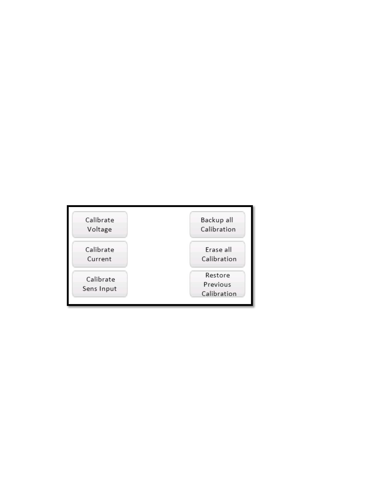
32. Calibrate Voltage: Click the Calibrate Voltage button (Figure 23).
Figure 23. MAXREFDES183# Calibrate Voltage screen.
Analog Devices Page 17 of 21
33. A screen (Figure 24) will show how to connect the precision DMM.
Figure 24. MAXREFDES183# Calibrate Voltage connection.
Please follow the instructions and click OK.
34. The MAXREFDES183# will now produce a “high” voltage of approximately 10V between
the UIO and GND (Figure 25). It should be stable in at least 5 digits, if not, then something
is wrong with your setup. Once the voltage has stabilized, read the exact number read
from the external DMM (as many digits as available), enter this value, and click OK.
Figure 25. MAXREFDES183# Calibrate +Voltage input.
Analog Devices Page 18 of 21
35. Next, the MAXREFDES183# will produce a “low” voltage of approximately “-10” between
the UIO and GND (Figure 26). It should be stable in at least 5 digits, if not, then something
is wrong with your setup. Once the voltage has stabilized, read the exact number read
from the external DMM, as many digits as available, enter this value and click OK.
Figure 26. MAXREFDES183# Calibrate -Voltage input.
36. The MAXREFDES183# will calculate and show the results for the gain and offset errors.
The results for the DAC in the MAX22000 should look like Figure 27. If the results make
sense, the display will show “DAC results are plausible”. If not, then most likely, something
was wrong with the measurement or data entered (i.e., typo, comma setting, missed the
“-" sign, or outputs were shorted during the measurement, etc.).
Figure 27. MAXREFDES183# Calibrate DAC voltage result.
Analog Devices Page 19 of 21
37. The MAXREFDES183# will allow the user to apply or ignore the calibration data,
regardless of if the results were plausible or not. If “IGNORE” is clicked, the displayed
values will be discarded, and previous factors will continue to be used. If “Apply” is clicked,
the values will be saved later in the process.
38. Next, the MAXREFDES183# will show the results (Figure 28) from calibrating for the ADC
in the MAX22000. The procedure is identical to that for the DAC to generate gain and
offset error data.
Figure 28. MAXREFDES183# Calibrate ADC voltage result.
39. The MAXREFDES183# has onboard nonvolatile memory (FLASH) which is used to store
calibration data for the DAC and ADC in MAX22000. The next screen in this process
(Figure 29) describes the storage of the calibration data for the MAXREFDES183#. Each
time the system is calibrated, the entire system calibration data will be saved to the
FLASH. The MAXREFDES183# asks the user to enter a name for the calibration data set.
Figure 29. MAXREFDES183# Calibrate data saved.
Analog Devices Page 20 of 21
40. Once the FLASH memory is full, the oldest calibration data set will be deleted. When
restoring older data, it can be selected by name.
41. The next step in the calibration process is to enter a description or name for the new
calibration data. After clicking OK, a keyboard will show up (Figure 30) and allow the user
to enter free-form text, that will be saved in the FLASH together with the calibration data.
Please enter the desired text and click OK.
Figure 30. MAXREFDES183# Calibrate data naming.
42. Calibrate Current: Calibrating the current is the same procedure as calibrating voltage,
but instead of a voltmeter across UIO and GND, a current meter must be connected in
series. Please follow the instructions on the screen to calibrate the DAC and ADC.
43. Calibrate Sense Inputs: Calibrating the SNS+/SNS- inputs (Figure 31) follows the same
procedure as calibrating voltage, with the exception that, for this operation, the UIO pin
must be connected to the SNS+ pin and GND must be connected to the SNS- pin.
Note: The sense inputs support multiple ranges, and each range must be calibrated
individually requiring eight measurements in total.
Figure 31. MAXREFDES183# Calibrate SENS inputs.
  • Page 1 1
  • Page 2 2
  • Page 3 3
  • Page 4 4
  • Page 5 5
  • Page 6 6
  • Page 7 7
  • Page 8 8
  • Page 9 9
  • Page 10 10
  • Page 11 11
  • Page 12 12
  • Page 13 13
  • Page 14 14
  • Page 15 15
  • Page 16 16
  • Page 17 17
  • Page 18 18
  • Page 19 19
  • Page 20 20
  • Page 21 21

Analog Devices MAXREFDES183 User guide

Type
User guide

Analog Devices MAXREFDES183 is a portable precision calibrator that provides voltage and current output and measurement, temperature measurement and simulation, and programmable gain amplifier for precise voltage sensing. It features a user-friendly interface with a touch-sensitive display, allowing for easy navigation and control. With its compact size and battery operation, the MAXREFDES183 is ideal for field calibration, laboratory testing, and educational purposes.

Ask a question and I''ll find the answer in the document

Finding information in a document is now easier with AI