Page is loading ...

THANK YOU.
We appreciate your trust and confidence in Hampton Bay with your purchase of this ventilation fan. At Hampton Bay we make
quality products to help you improve your home and give you peace of mind about your choice. Don’t forget to visit our website for
other Hampton Bay products. We hope you enjoy this new addition to your home and thanks again for choosing Hampton Bay.
Item # 986-755
Model # TY-50-A (HD)
Item # 986-793
Model #
TY
-
80
-
A(HD)
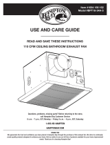
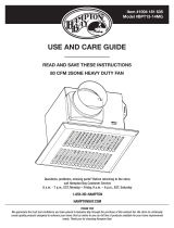
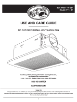
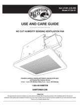
USE AND CARE GUIDE
VENTILATION FAN
Questions, problems, missing parts? Before returning to the store,
call Hampton Bay Customer Service
8 a.m.-6 p.m., EST, Monday-Friday
1-877-527-0313
HAMPTONBAY.COM

2
Table of Contents
Table of Contents .......................................................... 2
Safety Information ......................................................... 2
Warranty ......................................................................... 3
Pre-Installation .............................................................. 4
Planning For Successful Installation .......................... 4
Installation Options ..................................................... 4
15B
Tools Required .......................................................... 5
Materials Required ..................................................... 5
Hardware Included ..................................................... 5
Package Contents ...................................................... 6
Installation ..................................................................... 7
Troubleshooting .......................................................... 11
Care and Cleaning ...................................................... 11
Specifications .............................................................. 12
Ty-50-A (HD) Ultra Silent Ventilation Fan ................ 12
Ty-80-A (HD) Silent Ventilation Fan ........................ 12
Service Parts ............................................................... 13
TY-50-A (HD) Serviceable Parts .............................. 13
TY-80-A (HD) Serviceable Parts .............................. 14
Safet
y
Information
1. This ventilation fan is approved for use over a
bathtub or shower when installed in a GFCI
protected circuit. Do not use unapproved fans over
a bathtub or shower that is not approved for that
application.
2. Installation work must be carried out by a qualified
person(s) in accordance with all local and safety
codes including the rules for fire-rated
construction.
3. Always vent fans to the exterior and in compliance
with local codes.
4. Install ductwork in a straight line with minimal
bends.
5. Use 120 V, 60 Hz for the electrical supply and
properly ground the unit. Follow all local safety
and electrical codes.
6. Do not use this fan with any solid-state control
device; such as a dimmer switch. Solid-state
controls may cause harmonic distortion, which can
cause a motor humming noise.
7. To reduce the risk of fire or electric shock, do not
block air entry grill.
8. Sufficient air is needed for proper combustion and
exhausting of gases through the flute (chimney) of
fuel burning equipment to prevent back drafting.
Follow the heating equipment manufacturer’s guideline
and safety standards such as those published by the
National Fire Protection Association (NFPA), and the
American Society for Heating, Refrigeration and Air
conditioning Engineers (ASHRAE), and the local code
authorities.
WARNING: Not suitable for use as a range hood or
in areas where hazardous or explosive vapors are
present.
CAUTION: Do not install in locations where the air
temperature will exceed 104°F (40°C).
IMPORTANT: Exercise care to not damage
existing wiring when cutting or drilling into walls or
ceilings.
NOTE: Make sure duct work size is a minimum of
the discharge. Do not reduce. Reducing the duct
size can increase fan noise.
IMPORTANT: You may want to consult with a
professional electrician regarding the wiring of your
ventilation fan.
WARNING: To reduce the risk of electric shock,
please disconnect the electrical supply circuit to the
fan before installing light kit.
CAUTION: This product must be properly
grounded.

www.hamptonbay.com
3 Please contact 1-877-527-0313 for further assistance.
Warrant
y
The manufacturer warrants the products to be free from defects in materials and workmanship for a period of three (3)
years from date of purchase. This warranty applies only to the original consumer purchaser and only to products used in
normal use and service. If this product is found to be defective, the manufacturer’s only obligation, and your exclusive
remedy, is the repair or replacement of the product at the manufacturer’s discretion, provided that the product has not
been damaged through misuse, abuse, accident, modifications, alterations, neglect or mishandling. This warranty shall
not apply to any product that is found to have been improperly installed, set-up, or used in any way not in accordance
with the instructions supplied with the product. This warranty shall not apply to a failure of the product as a result of an
accident, misuse, abuse, negligence, alteration, faulty installation, or any other failure not relating to faulty material or
workmanship. This warranty shall not apply to the finish on any portion of the product, such as surface and/or
weathering, as this is considered normal wear and tear.
The manufacturer does not warrant and specially disclaims any warranty, whether express or implied, of
fitness for a particular purpose, other than the warranty contained herein. The manufacturer specifically
disclaims any liability and shall not be liable for any consequential or incidental loss or damage, including but
not limited to any labor/expense costs involved in the replacement or repair of said product.
Contact Customer Service Team at 1-877-527-0313 or visit www.hamptonbay.com.

4
Pre-Installation
PLANNING FOR SUCCESSFUL
INSTALLATION
When installing the ventilation fan in a new
construction site, install the main body of the fan and
duct work during the rough‑in construction of the
building. The grill should be installed after the finished
ceiling is in place.
When installing in existing construction, use the
dimensions on page 12 to determine the required hole
size for the ceiling. Grill edges should overlap finished
ceiling.
NOTE: If installing in existing construction, you must
have access to space above and below the installation
location.
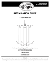
Do not install ventilation fan in areas where the duct
work will require configuration as shown.
INSTALLATION OPTIONS
We recommend installing the ventilation fan by securing the main body of the fan against one ceiling joist and using the
header bars as necessary for support of the adjoining joist.
There are multiple installation configurations possible for this ventilation fan. Not all configurations are shown. If your
installation requires a variation other than those shown, consult with a licensed contractor to determine the best
installation for your project. If you are replacing an existing fan, ensure that the new grill will adequately cover the
existing opening.

www.hamptonbay.com
5 Please contact 1-877-527-0313 for further assistance.
Pre-Installation
(
continued
)
15B TOOLS REQUIRED
Hammer
Safety
goggles
Phillips
screwdriver
Level
Electrical
tape
Drill
MATERIALS REQUIRED
Duct
vent
Duct
clamp
Duct
tape
Duct
piping
HARDWARE INCLUDED
NOTE: Hardware shown to actual size.
Part Description Quantity
AA Short screw (M4x12) 2
BB Long wood screw (ST4x30) 8
CC Screw (M4x6) 2
DD Quick connect 3
A
A
CC
DD

6
Pre-Installation
(
continued
)
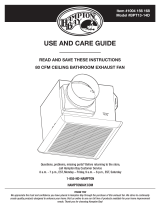
PACKAGE CONTENTS
Part Description
A Fan body
B Installation bracket IV
C Installation bracket II
D Installation bracket I
E Installation bracket III
F Grill
F
E
D
C
B
A

www.hamptonbay.com
7 Please contact 1-877-527-0313 for further assistance.
Installation
1
Determine joist width
□ Measure the distance from the center of the two
ceiling joists where you will be installing the
ventilation fan.
□ Use the table to determine the header bar
installation.
□ For configuration 1, proceed to step 2.
□ For configuration 2, proceed to step 3.
□ For configuration 3, proceed to step 4.
Use the following to determine the proper installation
configuration:
Width between the Joists Brackets Used Configuration
12 in. I 1
16 in. I, IV 2
19.2 in. I, II 3
2
Configuration 1, initial install
3
Configuration 2, initial install
□ Use long wood screws (BB) to loosely attach the
main body of fan (A) to ceiling joist in the four
locations shown.
□ Fit bracket I (D) against the main body of fan,
ensuring the bracket is snug against the
opposite ceiling joist.
□ Use long wood screws to loosely attach bracket I
to the opposite ceiling joist as shown.
□ Proceed to step 6.
□ Use long wood screws (BB) to loosely attach the
main body of fan (A) to the ceiling joist in the four
locations shown.
□ Fit bracket IV (B) against the main body of fan,
ensuring bracket I is snug against the opposite
ceiling joist.
□ Fit bracket I (D) against main the body of fan,
ensuring bracket IV is snug against the opposite
ceiling joist.
□ Use long wood screws to loosely attach bracket I
to opposite ceiling joist as shown.
□ Proceed to step 6.

8
Installation
(
continued
)
4
Configuration 3, preparation
5
Configuration 3, initial install
□ Connect bracket I (D) to bracket II (C) using two
M4x6 screws (CC).
□ Use long wood screws (BB) to loosely attach the
main body of fan (A) to the ceiling joist in the four
locations shown.
□ Fit connected brackets (C, D) against the main
body of fan, ensuring they are snug against the
opposite ceiling joist.
□ Use long wood screws to loosely attach bracket I
and 2 (C, D) to the opposite ceiling joist as
shown.
□ Proceed to step 6.
6
Final installation
7
Connect duct
□ Ensure the main body (A) is level.
□ Ensure the flange on the main body is flush with
the ceiling joist.
□ Firmly secure all screws on the main body and
any installed brackets.
□ Use long wood screws (BB) to secure the main
body flange to bottom of ceiling joist as shown.
□ Install a circular duct to outlet and secure it with
duct tape or clamps.
□ Install the duct (G) to the outlet with a gradient
1°~2° to the outside as shown.
G

www.hamptonbay.com
9 Please contact 1-877-527-0313 for further assistance.
Installation
(
continued
)
8
Using quick connect
9
Connect wiring from house to
box
WARNING: Wiring must comply with all applicable
electrical codes. Turn OFF power before removing or
installing connectors.
WARNING: COPPER TO COPPER ONLY. Do not use on
Aluminum wire.
CAUTION: Accessory part DD (quick connect) should meet
installation instructions below.
NOTE: Connector is reusable on solid wires of the same wire
gage or smaller. Do not reuse connector on stranded wires.
□ Strip the wires so half of the bare wire is showing.
□ Grip the wire firmly and push the stripped end of the
wire into the open port of connector (DD). Use only
one stripped end of the wire per port.
□ Verify the stripped end of the wire is fully inserted to
the back of the connector (DD).
NOTE: Important wire information. Maximum temperature
rating 105°C (221°F). 600 volts maximum for building wire
and 1000 volts maximum in signs and lighting fixtures.
Flammability rating of the wires must meet UL94-V2. The
acceptable wire range includes: Solid: 12-20 AWG,
Stranded: 12-16 AWG (≤19 STRAND); 18AWG (7 STRAND),
Tin bonded: 14-18 AWG (≤19 STRAND).
WARNING: Follow all local electrical and safety codes.
CAUTION: Never place a switch where it can be reached
from a tub or shower.
□ Connect house wires to ventilation fan wires.
□ Match colors as shown.
CAUTION: If your house wires do not match these colors,
determine what each house wire represents before
connecting. You may need to consult a licensed
electrician to determine this safely.
To switch box
Product wires
DD
Fan
(BLK)
L (BLK)
GRD
(GREEN & YELLOW)
HOUSE ELECTRICAL BOX
FAN SWITCH
120 VAC
LINE
IN
FAN ELECTRICAL BOX
N (WHT)

10
Installation
(
continued
)
10
Connect wiring from box to switch
11
Attach grill
WARNING: Follow all local electrical and safety codes.
□ Connect wires to switch using the quick connect
(DD) or wire nuts (not provided).
□ Match colors as shown.
WARNING: Failure to wire product correctly could result in
electrical shock, fire hazards, or damage to the product.
Consult a licensed electrician if you are unsure of your
ability to correctly install wiring.
□ Insert the mounting springs into the slots in the
grill (F).
□ Squeeze springs together and insert into the
main body.
120 VAC LINE IN
TO SWITCH BOX
BLACK WIRE
GREEN & YELLOW
(GRD)
BLACK WIRE (L)
WHITE WIRE (N)
DD
To switch box
Product wires
F

www.hamptonbay.com
11 Please contact 1-877-527-0313 for further assistance.
Troubleshootin
g
CAUTION: Do not install in locations where the air
temperature will exceed 104°F (40°C).
Problem Possible Cause Corrective Action
Fan will not turn on □ Power off □ Make sure the power supply is on
□ Faulty switch □ Test or replace the switch
□ Faulty wire connection □ Check wire in the switch box
Care and Cleanin
g
□ Before servicing or cleaning the unit, disconnect and lock the power supply at the panel to prevent the power from
being turned on.
□ Remove the grill by squeezing the springs and pulling down.
□ Wash and clean the grill in a sink and dry with a cloth.
□ Remove dust and dirt from the fan housing with a vacuum cleaner.
□ Dampen cloth with dish detergent, wipe the fan housing and dry with a cloth.
□ Replace the grill.

12
S
p
ecifications
TY-50-A (HD) ULTRA SILENT VENTILATION FAN
Model No. TY-50-A (HD)
Air direction 50 cfm
Voltage 120 V
Hertz 60 HZ
Duct diameter 4 in. (10.16 cm)
Noise 0.5 Sone
Power consumption (Watts) 20 W
Speed 900 rpm
Air deliver at 0.1" WG 50 cfm
Weight 10.5 lbs. (4.8 kg)
DIMENSIONS
Ceiling opening - length 9.5 in. (24.13 cm)
Ceiling opening - width 9.5 in. (24.13 cm)
Ceiling opening - depth 8.26 in. ( 21 cm)
Housing dimension - length 9.13 in. (23 cm)
Housing dimension - width 9.13 in. (23 cm)
Housing dimension - depth 7.75 in. (19.6 cm)
TY-80-A (HD) SILENT VENTILATION FAN
Model No. TY-80-A (HD)
Air direction 90 cfm
Voltage 120 V
Hertz 60 HZ
Duct diameter 4 in. (10.16 cm)
Noise 1.0 Sone
Power consumption (Watts) 30 W
Speed 1000 rpm
Air deliver at 0.1" WG 90 cfm
Weight 10.5 lbs. (4.8 kg)
DIMENSIONS
Ceiling opening - length 9.5 in. (24.13 cm)
Ceiling opening - width 9.5 in. (24.13 cm)
Ceiling opening - depth 8.26 in. ( 21 cm)
Housing dimension - length 9.13 in. (23 cm)
Housing dimension - width 9.13 in. (23 cm)
Housing dimension - depth 7.75 in. (19.6 cm)

www.hamptonbay.com
13 Please contact 1-877-527-0313 for further assistance.
Service Parts
TY-50-A (HD) SERVICEABLE PARTS
Part number Description Quantity
50-001
Quick connectors 3
50-002
Long wood screws 8
50-003
Short screw (M4x12) 2
50-004
Short screw (M4x6) 2
50-005
Grill 1
50-006
Complete assembled fan and housing 1
50-007
Complete suspension brackets 1
50-001
50-006
50-005
50-007
50-002
50-003 50-004

14
Service Parts
(
continued
)
TY-80-A (HD) SERVICEABLE PARTS
Part number Description Quantity
50-001
Quick connectors 2
80-001
Quick connectors 1
50-002
Long wood screws 8
50-003
Short screw (M4x12) 2
50-004
Short screw (M4x6) 2
50-005
Grill 1
80-006
Complete assembled fan and housing 1
50-007
Complete suspension brackets 1
50-001
80-006
50-005
50-007
50-002
80-001
50-003 50-004

www.hamptonbay.com
15 Please contact 1-877-527-0313 for further assistance.
This page intentionally left blank

Questions, problems, missing parts? Before returning to the store,
call Hampton Bay Customer Service
8 a.m.-6 p.m., EST, Monday-Friday
1-877-527-0313
HAMPTONBAY.COM
Retain this manual for future use.
20111010-M
/