
Installation and Operation Handbook Contents
Issue 8 Jul-99 Applies to 2416 controller software version 3.0 i
MODEL 2416 PID CONTROLLER
INSTALLATION AND OPERATION HANDBOOK
Contents Page
Chapter 1 INSTALLATION .................................................................1-1
Chapter 2 OPERATION ......................................................................2-1
Chapter 3 ACCESS LEVELS..............................................................3-1
Chapter 4 TUNING..............................................................................4-1
Chapter 5 PROGRAMMER OPERATION ..........................................5-1
Chapter 6 CONFIGURATION.............................................................6-1
Chapter 7 USER CALIBRATION........................................................7-1
Appendix A UNDERSTANDING THE ORDERING CODE...................A-1
Appendix B SAFETY and EMC INFORMATION .................................B-1
Appendix C TECHNICAL SPECIFICATION.........................................C-1
Appendix D UK OFFICE ADDRESSES................................................D-1
Appendix E LOAD CURRENT MONITORING AND DIAGNOSTICS... E-1
“This product is covered by one or more of the following US Patents:
5,484,206; Additional patents pending.
PDSIO and INSTANT ACCURACY are trademarks of Eurotherm.”

Installation and Operation Handbook Installation
2416 Controller 1-1
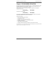
Chapter 1 INSTALLATION
The 2416 controller is a versatile, high stability temperature or process controller, with self
and adaptive tuning, in 1/16 DIN size (48 x 48mm). It has a modular hardware construction,
which accepts up to three plug-in output modules and one communications module, to satisfy
a wide range of control requirements. All 2416 controllers have a basic 8-segment
programmer built-in as standard.
The 2416 is available as either a:
• standard controller: Model 2416/CC
• setpoint programming controller: Models 2416/CP and 2416/P4
• motorised valve controller: Model 2416/VC
• setpoint programming motorised valve controller: Models 2416/VP and 2416/V4
This chapter consists of two parts:
• MECHANICAL INSTALLATION
• ELECTRICAL INSTALLATION.
Before proceeding, please read the chapter called, Safety and EMC Information.
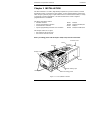
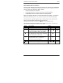
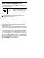
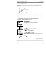
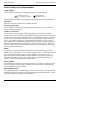
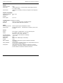
Figure 1-1 2416 1/16 DIN controller
Panel retaining clips
Ratchets
Sleeve
Terminal covers
Label
Latching ears
Panel sealing gasket
Display screen

Installation Installation and Operation Handbook
1-2 2416 Controller
WARNING
You must ensure that the controller is correctly configured for your application.
Incorrect configuration could result in damage to the process being controlled, and/or
personal injury. It is your responsibility as the installer to ensure that the configuration
is correct. The controller may either have been configured when ordered, or may need
configuring now. See Chapter 6, Configuration.
MECHANICAL INSTALLATION
Controller labels
The labels on the sides of the controller identify the ordering code, the serial number, and the
wiring connections.
Appendix A, Understanding the Ordering Code explains the hardware and software
configuration of your particular controller.
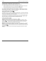
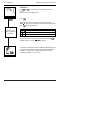
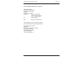
Outline dimensions
AUTO
RUN
HOLD
2416
MAN
OP1
OP2
SP2
REM
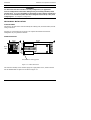
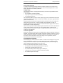
Figure 1-2 Outline dimensions
The electronic assembly of the controller plugs into a rigid plastic sleeve, which in turn fits
into the standard DIN size panel cut-out shown in Figure 1-3.
48mm
150mm
1.89in
5.91in
48mm
1.89in
IP65, NEMA 4X sealing gasket
OP1
OP2
SP2
REM
2416

Installation and Operation Handbook Installation
2416 Controller 1-3
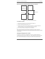
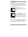
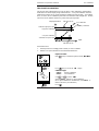
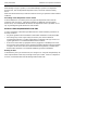
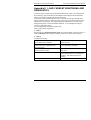
Panel cut-out and recommended minimum spacing of controllers
Figure 1-3 Panel cut-outs and minimum spacing
To install the controller
1. Prepare the control panel cut-out to the size shown in Figure 1-3.
2. Insert the controller through the panel cut-out.
3. Spring the upper and lower panel retaining clips into place. Secure the controller in
position by holding it level and pushing both retaining clips forward.
4. Peel off the plastic film protecting the front of the indicator.
Note: If the panel retaining clips subsequently need removing, in order to extract the
controller from the control panel, they can be unhooked from the side with either your fingers
or a screwdriver.
Unplugging and plugging-in the controller
If required, the controller can be unplugged from its sleeve by easing the latching ears
outwards and pulling it forward out of the sleeve. When plugging the controller back into its
sleeve, ensure that the latching ears click into place in order to secure the IP65 sealing.
38mm (1.5in)
10mm (0.4in)
Panel cut-out
45 x 45mm
1.77 x 1.77in
-0
+0.6
-0
+0.02

Installation Installation and Operation Handbook
1-4 2416 Controller
ELECTRICAL INSTALLATION
This section consists of five topics:
• Rear terminal layout
• Fixed connections
• Plug-in module connections
• Typical wiring diagram
• Motorised valve connections
All electrical connections are made to the screw terminals at the rear of the controller. These
screw terminals accept wire sizes from 0.5 to 2.5mm
2
(14 to 22 awg) and should be tightened
to a torque of 0.4 Nm (3.5 lb in). If you wish to use crimp connectors, we recommend AMP
part number 16500. These accept wire sizes from 0.5 to 1.5 mm
2
(16 to 22 AWG).
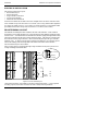
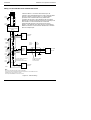
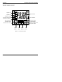
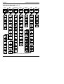
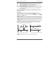
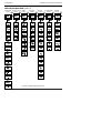
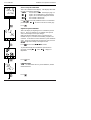
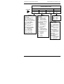
REAR TERMINAL LAYOUT
The terminals are arranged in three columns at the rear of the controller. Each column is
protected by a clear plastic hinged cover to prevent hands or metal making accidental contact
with live wires. Viewed from the rear and with the controller upright, the right-hand column
carries the connections for the power supply and sensor input. The other two columns carry
the connections to the plug-in modules. The connections depend upon the type of module
installed, if any. To discover which plug-in modules are installed in your controller, please
refer to the ordering code and wiring data on the labels on the sides of the controller.
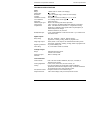
The rear terminal layout is shown below.
Note: The plug-in sleeve supplied with high voltage controllers are keyed to prevent a low
voltage unit being inserted into them.
Figure 1-4 Rear terminal layout
*The ground connection is provided as a return for internal EMC filters. It is not required
for safety purposes, but must be connected in order to satisfy EMC requirements.
+
PV
−
RTD/
Pt100
N
L
2B
1B
1A
3B
2A
3A
Line
Neutral
Ground*
+
−
T/C
VI
HD
M
O
D
U
L
E
3
V+
HE
V
−
HF
HA
HB
HC
C
O
M
M
S
M
O
D
U
L
E
2
M
O
D
U
L
E
1
20
−
29Vac/dc
Neutral
N
24
+
−
Low voltage supply
85 to 264Vac

Installation and Operation Handbook Installation
2416 Controller 1-5
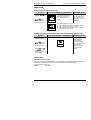
FIXED CONNECTIONS
The power supply and sensor inputs are always wired to the same fixed positions whatever
plug-in modules are installed.
Power supply connections
These are as shown in Figure 1-4.
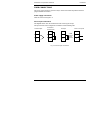
Sensor input connections
The diagrams below show the connections for the various types of input.
The input will have been configured in accordance with the ordering code.
Fig 1-5 Sensor input connections
VI
V+
V-
VI
V+
V-
VI
V+
V-
VI
V+
V-
Thermocouple
Resistance
thermometer
mA input Volts or mV inputs
+
-
PV
2.49Ω
current
sense
resistor

Installation Installation and Operation Handbook
1-6 2416 Controller
PLUG-IN MODULE CONNECTIONS
In Figure 1-4, Modules 1, 2 and 3, and Comms are plug-in modules.
Modules 1, 2 and 3
Module positions 1, 2 and 3 each have two terminals. They will accept four types of module:
Relay, Logic (non-isolated), Triac, and DC (non-isolated) output.
Collectively, these can be configured to operate in six different ways:
Heating control
Cooling control
Alarm output
Program event output
PDSIO mode 1*, which provides logic heating using a Eurotherm TE10S solid state relay
with feedback of a load failure alarm.
PDSIO mode 2*, which provides logic heating using a Eurotherm TE10S solid state
relay, with feedback of the load current reading and two alarms: solid state relay failure
and heater circuit failure.
* PDSIO stands for ‘Pulse Density Signalling Input/Output’. This is a proprietary technique
developed by Eurotherm for bi-directional transmission of analogue and digital data over a
simple 2-wire connection.
Snubbers
The relay and triac modules have an internal 15nF/100Ω ‘snubber’ connected across their
output, which is used to prolong contact life and to suppress interference when switching
inductive loads, such as mechanical contactors and solenoid valves.
WARNING
When the relay contact is open or the triac is off, the snubber circuit passes 0.6mA at
110Vac and 1.2mA at 240Vac. You must ensure that this current, passing through the
snubber, will not hold on low power electrical loads. It is your responsibility as the
installer to ensure that this does not happen. If the snubber circuit is not required, it
can be removed from the relay module (but not
the triac) by breaking the PCB track
that runs crosswise adjacent to the edge connectors of the module. Insert the blade of a
screwdriver into one of the two slots that bound it, and twist.
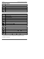
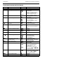
The table below shows the module connections and which functions each module can
perform. The heating output is normally connected to module 1, the cooling output to
module 2 and the alarm output to module 3, although the actual function of each module will
depend upon how your controller has been configured.
Note: Module 1 is connected to terminals 1A and 1B
Module 2 is connected to terminals 2A and 2B
Module 3 is connected to terminals 3A and 3B.

Installation and Operation Handbook Installation
2416 Controller 1-7
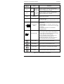
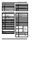
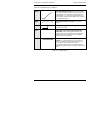
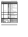
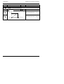
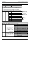
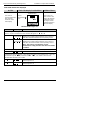
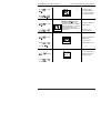
Module type Terminal identity Possible functions
A B
Relay: 2-pin
(2A, 264 Vac max.)
Heating, Cooling, or Alarm output
Program event output
Valve raise or lower
Logic: non-isolated
(18Vdc at 20mA)
+
−
Heating, Cooling, or Alarm output
PDSIO mode 1,
PDSIO mode 2,
Program event
Triac
(1A, 30 to 264Vac)
Heating, Cooling,
Program event
Valve raise or lower
DC control: non-isolated
(10Vdc, 20mA max.)
+
−
Heating, Cooling.
Retransmission of PV, setpoint or
control output
Table 1-1 Module 1, 2 and 3 connections
To check which modules are installed in your particular controller, and which functions they
are configured to perform, refer to the ordering code and the wiring information on the
controller side labels.
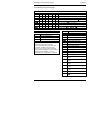
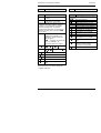
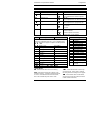
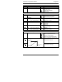
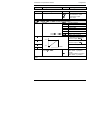
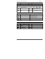
Communications module
The Communications module position will accept any of the modules listed in Table 1-2
below.
The serial communications can be configured for either Modbus, or EI bisynch protocol.
Communications module
Terminal identity (COMMS)
Module type HA HB HC HD HE HF
2-wire EIA-485 serial
communications
−− −
Common A (+)
B (−)
EIA-232 serial
communications
−− −
Common Rx Tx
4-wire EIA-485 serial
communications
− A′
(Rx+)
B′
(Rx−)
Common
A
(Tx+)
B
(Tx−)
PDSIO Setpoint
retransmission
−− − −
Signal Common
PDSIO remote setpoint input -- -- -- --
Signal Common
Table 1-2 Communications connections
Line
Load

Installation Installation and Operation Handbook
1-8 2416 Controller
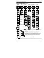
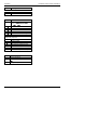
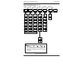
Wiring of 2-wire EIA-485 serial communications link
Com
Note:
All resistors are 220 ohm 1/4W carbon composition.
Local grounds are at equipotential. Where equipotential is not available wire into
separate zones using a galvanic isolator.
Use a repeater (KD845) for more than 32 units.
A
B
PC
Eurotherm Universal
Communications Interface
KD485
RXTX
Com
Com
TXRX
Up to 32 S2000 controllers or
Interface Units may
be included on the
network
232
Com B
A
Com
A
B
Com
A
B
Com
A
B
Local Earth
Local
Ground
Zone 1
Local
Ground
Zone 2
Area 1
Com
A
B
E
F
D
Local
Earth
HE
HF
HD
Series 2000
Controller
HE
HF
HD
Series 2000
Controller
For reasons of safety
do
not
connect to
local earth here.
Local
Earth
Local
Earth
Local
Earth
Local
Earth
Local
Earth
HE
HF
HD
Series 2000
Controller
Galvanic
Isolation
Barrier
Local
Ground
Zone 1
Local
Ground
Zone 1
Local
Ground
Zone 1
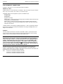
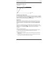
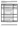
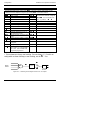
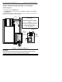
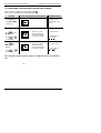
Figure 1-6 EIA-485 wiring
2-wire EIA-485 is a connection which allows up to 32
controllers to be multi-dropped from a single communications
link over a distance of up to 1.2Km. To ensure reliable
operation of the communications link, (without data
corruption due to noise or line reflections) the connections
between the controller should be made using a twisted pair of
wires inside a screened cable with the connections
terminated with resistors in the manner shown in this
diagram. This diagram also shows the use of a Eurotherm
KD485 converter to connect the EIA-485 link into a standard
EIA-232 computer port.

Installation and Operation Handbook Installation
2416 Controller 1-9
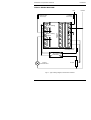
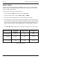
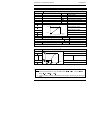
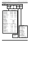
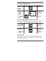
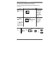
TYPICAL WIRING DIAGRAM
Fig 1-7 Typical wiring diagram, Model 2416 Controller
TE10 Solid
State Relay
Cooling Power
Fuse 1A(T)
Heating power fuse
(load dependent)
Cooling
Solenoid Valve
Heater
T/C
+
N
L
V+
VI
V-
2B
1B
1A
3B
2A
3A
C
O
M
M
S
Logic heating
output
Triac cooling
output
Line Neutral
Controller
Fuse 2A(T)
-
HD
HE
HF
HA
HB
HC

Installation Installation and Operation Handbook
1-10 2416 Controller
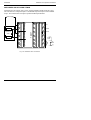
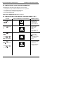
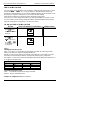
MOTORISED VALVE CONNECTIONS
Motorised valves are wired to relay, or triac, outputs installed in module positions 1 and 2.
The convention is to configure Output 1 as the RAISE output and Output 2 as the LOWER
output. The controller does not require a position feedback potentiometer.
Fig 1-8 Motorised valve connections
RTD/
Pt100
Line
Neutral
Ground
+
−
+
PV
−
Motor supply
LOWER
RAISE
Motorised
valve
T/C
M
O
D
U
L
E
3
C
O
M
M
S
M
O
D
U
L
E
2
M
O
D
U
L
E
1
N
L
V+
VI
V-
2B
1B
1A
3B
2A
3A
HD
HE
HF
HA
HB
HC

Installation and Operation Handbook Operation
2416 Controller 2-1
Chapter 2 OPERATION
This chapter has nine topics:
• FRONT PANEL LAYOUT
• BASIC OPERATION
• OPERATING MODES
• AUTOMATIC MODE
• MANUAL MODE
• PARAMETERS AND HOW TO ACCESS THEM
• NAVIGATION DIAGRAM
• PARAMETER TABLES
• ALARM MESSAGES

Operation Installation and Operation Handbook
2-2 2416 Controller
FRONT PANEL LAYOUT
AUTO
RUN
HOLD
2416
MAN
OP1
OP2
SP2
REM
Figure 2-1 Front panel layout
Remote setpoint active
(flashes for comms)
Output 2 on
Output 1 on
Setpoint 2 active
Auto/Man button
Auto mode active
Upper readout
Lower readout
Manual mode active
Program running
Run/Hold button
(Press & hold to reset)
Program in Hold
Page
Button
Scroll
Button
Down
Button
Up
Button
2416
REM
OP1
SP2
OP2

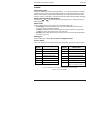
Installation and Operation Handbook Operation
2416 Controller 2-3
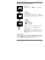
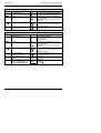
Button or
indicator
Name Explanation
OP1
Output
1
If a DC
output is
installed
When lit, it indicates that the output installed in
module position 1 is on. This is normally the heating
output on a temperature controller.
OP2
Output
2
OP1 &
OP2 will
not light
When lit, it indicates that the output installed in
module position 2 is on. This is normally the cooling
output on a temperature controller.
SP2 Setpoint 2
When lit, this indicates that setpoint 2, (or a setpoint
3-16) has been selected.
REM Remote setpoint
When lit, this indicates that a remote setpoint input
has been selected.
‘REM’ will also flash when communications is active.
AUTO
MAN
Auto/Manual
button
When pressed, this toggles between automatic and
manual mode:
• If the controller is in automatic mode the AUTO
light will be lit.
• If the controller is in manual mode, the MAN light
will be lit.
The Auto/Manual button can be disabled in
configuration level.
RUN
HOLD
Run/Hold button
• Press once to start a program (RUN light on.)
• Press again to hold a program (HOLD light on)
• Press again to cancel hold and continue running
(HOLD light off and RUN light ON)
• Press and hold in for two seconds to reset a
program (RUN and HOLD lights off)
The RUN light will flash at the end of a program.
The HOLD light will flash during holdback.
Page button Press to select a new list of parameters.
Scroll button Press to select a new parameter in a list.
Down button Press to decrease a value in the lower readout.
Up button Press to increase a value in lower readout.
Figure 2-2 Controller buttons and indicators

Operation Installation and Operation Handbook
2-4 2416 Controller
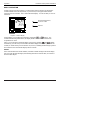
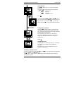
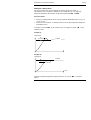
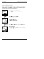
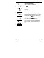
BASIC OPERATION
Switch on the power to the controller. It runs through a self-test sequence for about three
seconds and then shows the temperature, or process value, in the upper readout and the
setpoint in the lower readout. This is called the Home display. It is the one that you will use
most often.
Figure 2-3 Home display
On this display you can adjust the setpoint by pressing the or buttons. Two
seconds after releasing either button, the display blinks to show that the controller has
accepted the new value.
Note: You can get back to the Home display at any time by pressing
and together.
Alternatively you will always be returned to the Home display if no button is pressed for 45
seconds, or whenever the power is turned on. If, however, a flashing alarm message is present
the controller reverts to the Home display after 10 seconds.
Alarms
If the controller detects an alarm condition, it flashes an alarm message in the Home display.
For a list of all the alarm messages, their meaning and what to do about them, see Alarms at
the end of this chapter.
Measured temperature,
or process value
Setpoint
D
D

Installation and Operation Handbook Operation
2416 Controller 2-5
OPERATING MODES
The controller has two basic modes of operation:
• Automatic mode in which the output power is automatically adjusted to maintain the
temperature or process value at the setpoint.
• Manual mode in which you can adjust the output power independently of the setpoint.
You toggle between the modes by pressing the
AUTO/MAN
button. The displays which
appear in each of these modes are explained in this chapter.
Two other modes are also available:
• Remote Setpoint mode in which the setpoint is generated from an external source.
In this mode the
REM
light will be on.
• Programmer mode which is explained in Chapter 5, Programmer Operation.

Operation Installation and Operation Handbook
2-6 2416 Controller
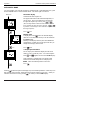
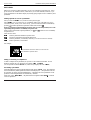
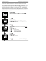
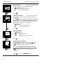
AUTOMATIC MODE
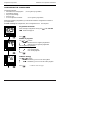
You will normally work with the controller in automatic mode. If the
MAN
light is on, press
the
AUTO/MAN
button to select automatic mode. The
AUTO
light will come on.
Power on
x 2
The Home display
Check that the
AUTO
light is on.
The upper readout shows the measured temperature, or
process value. The lower readout shows the setpoint.
To adjust the setpoint up or down, press
or .
(Note: If Setpoint Rate Limit has been enabled, then the
lower readout will show the active setpoint. If
or
is pressed, it will change to show and allow adjustment of,
the target setpoint.)
Press
once
Display units
A single press of the
button will flash the display
units for 0.5 seconds, after which you will be returned to
the Home display.
Flashing of the display units may have been disabled in
configuration, in which case a single press will take you
straight to the display shown below.
Press
twice
% Output power demand
The % output power demand is displayed in the lower
readout. This is a read-only value. You cannot adjust it.
Press and together to return to the Home display.
If the controller is configured as Valve Position and
Manual is selected the Output Power is displayed as
. This is the inferred position of the valve
Press
Pressing from the Output Power display may access further parameters. These may be in
this scroll list if the ‘Promote’ feature has been used (see Chapter 3, Edit Level). When you
reach the end of this scroll list, pressing
will return you to the Home display.
D
D
0

Installation and Operation Handbook Operation
2416 Controller 2-7
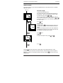
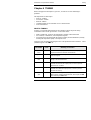
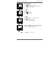
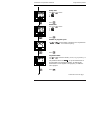
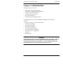
MANUAL MODE
If the
AUTO
light is on, press the
AUTO/MAN
button to select manual mode. The
MAN
light will come on.
Power on
x 2
The Home display
Check that the
MAN
light is on.
The upper readout shows the measured temperature or
process value. The lower readout shows the % output.
To adjust the output, press
or .
(Note: If Output Rate Limit has been enabled, then the
lower readout will show the working output. If
or
is pressed, it will change to show and allow adjustment of,
the target output.)
Press once
Display units
A single press of
will flash the display units for 0.5
seconds, after which you will be returned to the Home
display.
Flashing of the display units may have been disabled in
configuration in which case you a single press will take
you straight to the display shown below.
Press
twice
Setpoint
To adjust the setpoint value, press
or .
Press
Pressing from the Output Power display may access further parameters. Other
parameters may be in this scroll list if the ‘Promote’ feature has been used (see Chapter 3,
Edit Level). When you reach the end of this scroll list, pressing
will return you to the
Home display.
D
D
0

Operation Installation and Operation Handbook
2-8 2416 Controller
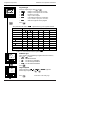
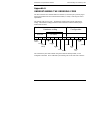
PARAMETERS AND HOW TO ACCESS THEM
Parameters are settings within the controller that determine how it will operate.
For example, alarm setpoints are parameters that set the points at which alarms will occur.
For ease of access, the parameters are arranged in lists as shown in the navigation diagram on
the following page. The names of these lists are called the list headers. The lists are:
Home list
Run list
Programmer list
Alarm list
Autotune list
PID list
Motor list
Setpoint list
Input list
Output list
Communications list
Information list
Access list.
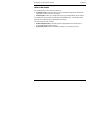
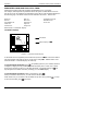
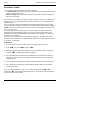
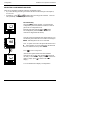
Each list has a ‘List Header’ display.
List header displays
Figure 2-4 Typical list header display
A list header can be recognised by the fact that it always shows
‘
’ in the lower readout.
The upper readout is the name of the list. In the above example, indicates that it is the
Alarm list header. List header displays are read-only.
To step through the list headers press
. Depending upon how your controller has been
configured, a single press may momentarily flash the display units. In this case, a double
press will be necessary to take you to the first list header. Continued pressing of
will
step through the list headers eventually returning you to the Home display.
To step through the parameters within a particular list, press
.
When you reach the end of the list, you will return to the list header.
From within a list you can return to the list header at any time can by pressing
. To step
to the next list header, press once again.
List header
Always displays ‘
’
)
)O6

Installation and Operation Handbook Operation
2416 Controller 2-9
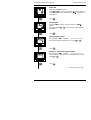
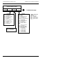
Parameter names
In the navigation diagram, (Fig2-6) each box depicts the display for a selected parameter.
The upper readout shows the name of the parameter and the lower readout its value.
The Operator parameter tables later in this chapter list all the parameter names and their
meaning.
The navigation diagram shows all the parameters that can, potentially, be present in the
controller. In practice, only those associated with a particular configuration will appear.
The shaded boxes in the diagram indicate parameters that are hidden in normal operation.
To see all the available parameters, you must select Full access level. For more information
about this, see Chapter 3, Access Levels.
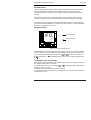
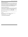
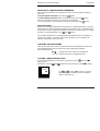
Parameter displays
Figure 2-5 Typical parameter display
Parameter displays show the controller’s current settings. The layout of parameter displays
is always the same: the upper readout shows the parameter name and the lower readout its
value. Alterable parameters can be changed using
or . In the above example, the
parameter mnemonic is (indicating Alarm 1, full scale low), and the parameter value
is .
To change the value of a parameter
First, select the required parameter. The parameter name is shown in the upper readout and
the parameter value in the lower readout.
To change the parameter value, press either
or . During adjustment, single presses
change the value by one digit.
Keeping the button pressed speeds up the rate of change.
Two seconds after releasing either button, the display blinks to show that the controller has
accepted the new value.
Parameter name
Parameter value
)
D
Page is loading ...
Page is loading ...
Page is loading ...
Page is loading ...
Page is loading ...
Page is loading ...
Page is loading ...
Page is loading ...
Page is loading ...
Page is loading ...
Page is loading ...
Page is loading ...
Page is loading ...
Page is loading ...
Page is loading ...
Page is loading ...
Page is loading ...
Page is loading ...
Page is loading ...
Page is loading ...
Page is loading ...
Page is loading ...
Page is loading ...
Page is loading ...
Page is loading ...
Page is loading ...
Page is loading ...
Page is loading ...
Page is loading ...
Page is loading ...
Page is loading ...
Page is loading ...
Page is loading ...
Page is loading ...
Page is loading ...
Page is loading ...
Page is loading ...
Page is loading ...
Page is loading ...
Page is loading ...
Page is loading ...
Page is loading ...
Page is loading ...
Page is loading ...
Page is loading ...
Page is loading ...
Page is loading ...
Page is loading ...
Page is loading ...
Page is loading ...
Page is loading ...
Page is loading ...
Page is loading ...
Page is loading ...
Page is loading ...
Page is loading ...
Page is loading ...
Page is loading ...
Page is loading ...
Page is loading ...
Page is loading ...
Page is loading ...
Page is loading ...
Page is loading ...
Page is loading ...
Page is loading ...
Page is loading ...
Page is loading ...
Page is loading ...
Page is loading ...
Page is loading ...
Page is loading ...
Page is loading ...
Page is loading ...
Page is loading ...
Page is loading ...
Page is loading ...
Page is loading ...
Page is loading ...
Page is loading ...
Page is loading ...
Page is loading ...
Page is loading ...
Page is loading ...
-
 1
1
-
 2
2
-
 3
3
-
 4
4
-
 5
5
-
 6
6
-
 7
7
-
 8
8
-
 9
9
-
 10
10
-
 11
11
-
 12
12
-
 13
13
-
 14
14
-
 15
15
-
 16
16
-
 17
17
-
 18
18
-
 19
19
-
 20
20
-
 21
21
-
 22
22
-
 23
23
-
 24
24
-
 25
25
-
 26
26
-
 27
27
-
 28
28
-
 29
29
-
 30
30
-
 31
31
-
 32
32
-
 33
33
-
 34
34
-
 35
35
-
 36
36
-
 37
37
-
 38
38
-
 39
39
-
 40
40
-
 41
41
-
 42
42
-
 43
43
-
 44
44
-
 45
45
-
 46
46
-
 47
47
-
 48
48
-
 49
49
-
 50
50
-
 51
51
-
 52
52
-
 53
53
-
 54
54
-
 55
55
-
 56
56
-
 57
57
-
 58
58
-
 59
59
-
 60
60
-
 61
61
-
 62
62
-
 63
63
-
 64
64
-
 65
65
-
 66
66
-
 67
67
-
 68
68
-
 69
69
-
 70
70
-
 71
71
-
 72
72
-
 73
73
-
 74
74
-
 75
75
-
 76
76
-
 77
77
-
 78
78
-
 79
79
-
 80
80
-
 81
81
-
 82
82
-
 83
83
-
 84
84
-
 85
85
-
 86
86
-
 87
87
-
 88
88
-
 89
89
-
 90
90
-
 91
91
-
 92
92
-
 93
93
-
 94
94
-
 95
95
-
 96
96
-
 97
97
-
 98
98
-
 99
99
-
 100
100
-
 101
101
-
 102
102
-
 103
103
-
 104
104


