Page is loading ...


2016-02-15
PHOENIX CONTACT 8089_en_03
Smart Managed Narrow Switch
UM EN FL SWITCH SMN 6TX/2POF-PN
03
—
Designation Version Order No.
FL SWITCH SMN 6TX/2POF-PN 2700290
FL SWITCH SMN 8TX-PN 2989501
FL SWITCH SMN 6TX/2FX 2989543
FL SWITCH SMN 6TX/2FX-SM 2989556
User manual
Designation:
Revision:
Order No.:
This user manual is valid for:

PHOENIX CONTACT
Please observe the following notes
User group of this manual
The use of products described in this manual is oriented exclusively to:
– Qualified electricians or persons instructed by them, who are familiar with applicable
standards and other regulations regarding electrical engineering and, in particular, the
relevant safety concepts.
– Qualified application programmers and software engineers, who are familiar with the
safety concepts of automation technology and applicable standards.
Explanation of symbols used and signal words
How to contact us
Internet Up-to-date information on Phoenix Contact products and our Terms and Conditions can be
found on the Internet at:
phoenixcontact.com
Make sure you always use the latest documentation.
It can be downloaded at:
phoenixcontact.net/products
Subsidiaries If there are any problems that cannot be solved using the documentation, please contact
your Phoenix Contact subsidiary.
Subsidiary contact information is available at phoenixcontact.com.
Published by PHOENIX CONTACT GmbH & Co. KG
Flachsmarktstraße 8
32825 Blomberg
GERMANY
Should you have any suggestions or recommendations for improvement of the contents and
layout of our manuals, please send your comments to:
This is the safety alert symbol. It is used to alert you to potential personal injury
hazards. Obey all safety measures that follow this symbol to avoid possible
injury or death.
There are three different categories of personal injury that are indicated with a
signal word.
DANGER This indicates a hazardous situation which, if not avoided, will
result in death or serious injury.
WARNING This indicates a hazardous situation which, if not avoided, could
result in death or serious injury.
CAUTION This indicates a hazardous situation which, if not avoided, could
result in minor or moderate injury.
This symbol together with the signal word NOTE and the accompanying text
alert the reader to a situation which may cause damage or malfunction to the
device, hardware/software, or surrounding property.
This symbol and the accompanying text provide the reader with additional
information or refer to detailed sources of information.

Please observe the following notes
PHOENIX CONTACT
General terms and conditions of use for technical documentation
Phoenix Contact reserves the right to alter, correct, and/or improve the technical
documentation and the products described in the technical documentation at its own
discretion and without giving prior notice, insofar as this is reasonable for the user. The
same applies to any technical changes that serve the purpose of technical progress.
The receipt of technical documentation (in particular user documentation) does not
constitute any further duty on the part of Phoenix Contact to furnish information on
modifications to products and/or technical documentation. You are responsible to verify the
suitability and intended use of the products in your specific application, in particular with
regard to observing the applicable standards and regulations. All information made
available in the technical data is supplied without any accompanying guarantee, whether
expressly mentioned, implied or tacitly assumed.
In general, the provisions of the current standard Terms and Conditions of Phoenix Contact
apply exclusively, in particular as concerns any warranty liability.
This manual, including all illustrations contained herein, is copyright protected. Any
changes to the contents or the publication of extracts of this document is prohibited.
Phoenix Contact reserves the right to register its own intellectual property rights for the
product identifications of Phoenix Contact products that are used here. Registration of such
intellectual property rights by third parties is prohibited.
Other product identifications may be afforded legal protection, even where they may not be
indicated as such.

8089_en_03 PHOENIX CONTACT 3
Table of contents
1 Smart Managed Narrow Switch .................................................................................................9
1.1 Features ................................................................................................................9
1.1.1 Dimensions of the SMN .......................................................................11
1.2 Status and diagnostics indicators ........................................................................13
1.2.1 Firmware versions and their functions ..................................................14
2 Mounting and installation .........................................................................................................15
2.1 Mounting and removing the SMN ........................................................................15
2.2 Installing the Smart Managed Narrow Switch ......................................................16
2.2.1 Connecting the 24 V DC supply voltage ...............................................16
2.2.2 Signal contact ......................................................................................17
2.2.3 Assignment of the RJ45 Ethernet connectors ......................................17
2.2.4 RS-232 interface for external management ..........................................18
2.3 Grounding............................................................................................................18
3 Startup and functions ...............................................................................................................19
3.1 Basic settings ......................................................................................................19
3.1.1 Delivery state/default settings ..............................................................19
3.2 Using Smart mode...............................................................................................20
3.2.1 Activating Smart mode .........................................................................20
3.3 Frame switching ..................................................................................................22
3.3.1 Store and forward ................................................................................22
3.3.2 Multi-address function ..........................................................................22
3.3.3 Learning addresses .............................................................................22
3.3.4 Prioritization .........................................................................................23
4 Configuration and diagnostics ..................................................................................................25
4.1 Making contact between the SMN and PC for initial configuration.......................25
4.1.1 Operation with static IP addresses .......................................................25
4.2 Web-based management (WBM) ........................................................................27
4.2.1 General function ...................................................................................27
4.2.2 Requirements for the use of WBM .......................................................28
4.2.3 Functions/information in WBM .............................................................28
4.3 Simple Network Management Protocol (SNMP)..................................................47
4.3.1 General function ...................................................................................47
4.3.2 Schematic view of SNMP management ...............................................47
4.3.3 RFC 1213 MIB - MIB II .........................................................................51
4.3.4 RMON MIB (1.3.6.1.2.1.16) .................................................................58
4.3.5 Bridge MIB (1.3.6.1.2.1.17) ..................................................................64
4.3.6 pBridgeMIB (1.3.6.1.2.1.17.6) ..............................................................66
4.3.7 qBridgeMIB (1.3.6.1.2.1.17.7) ..............................................................67
4.3.8 rstp MIB (1.3.6.1.2.1.17.11) .................................................................70
4.3.9 IANAifType MIB (1.3.6.1.2.1.30) ..........................................................70

FL SWITCH SMN
4PHOENIX CONTACT 8089_en_03
4.3.10 IF MIB (1.3.6.1.2.1.31) .........................................................................70
4.3.11 pnoRedundancy MIB 1.3.6.1.4.1.24686 ..............................................73
4.3.12 Private MIBs .........................................................................................74
4.4 Management via local RS-232 communication interface ...................................103
4.4.1 General function .................................................................................103
4.4.2 User interface functions .....................................................................104
4.4.3 Starting with faulty software (firmware) ..............................................107
5 (Rapid) Spanning Tree ...........................................................................................................109
5.1 General function ................................................................................................109
5.2 (R)STP startup...................................................................................................110
5.2.1 Enabling (R)STP on all switches involved ..........................................110
5.2.2 Connection failure - Example .............................................................118
5.2.3 Mixed operation of RSTP and STP ....................................................119
5.2.4 Topology detection of a Rapid Spanning Tree network (RSTP) .........119
5.2.5 Configuration notes for Rapid Spanning Tree ....................................122
6 Media Redundancy Protocol (MRP) ......................................................................................133
6.1 General function ................................................................................................133
6.2 MRP manager ...................................................................................................133
6.2.1 Network examples .............................................................................134
6.3 Enabling web pages for using MRP in WBM......................................................135
6.4 Configuration of MRP ........................................................................................136
6.4.1 MRP general ......................................................................................136
6.4.2 MRP configuration .............................................................................137
7 Multicast filtering ...................................................................................................................139
7.1 Basics................................................................................................................139
7.2 Enabling the web pages for multicast filtering in WBM.......................................139
7.3 Static multicast groups.......................................................................................139
7.3.1 “Current Multicast Groups” web page ................................................140
7.3.2 Creating static multicast groups .........................................................140
7.3.3 Procedure for creating a multicast group ............................................142
7.4 Dynamic multicast groups..................................................................................144
7.4.1 Internet Group Management Protocol (IGMP) ....................................144
7.4.2 “General Multicast Configuration” web page ......................................146
8 Virtual Local Area Network (VLAN) ........................................................................................147
8.1 Basics................................................................................................................147
8.2 Enabling the VLAN web pages in web-based management ..............................147
8.2.1 Management VLAN ID .......................................................................147
8.2.2 Changing the management VLAN ID .................................................148

Table of contents
8089_en_03 PHOENIX CONTACT 5
8.3 General VLAN configuration ..............................................................................148
8.4 Current VLANs ..................................................................................................149
8.4.1 Static VLANs ......................................................................................150
8.4.2 VLAN port configuration .....................................................................151
8.4.3 VLAN port configuration table ............................................................151
8.5 Setting up static VLANs .....................................................................................152
8.6 VLAN and (R)STP .............................................................................................153
9 Operation as a PROFINET device .........................................................................................155
9.1 Preparing the switch for PROFINET mode ........................................................155
9.2 Switch as a PROFINET device ..........................................................................156
9.2.1 Configuration in the engineering tool ..................................................156
9.2.2 Configuring the switch as a PROFINET device ..................................157
9.2.3 Configuration via the engineering tool ................................................158
9.2.4 PROFINET flashing function ..............................................................159
9.2.5 Device naming ...................................................................................159
9.2.6 Operating in the PROFINET environment ..........................................159
9.3 PROFINET alarms.............................................................................................159
9.3.1 Alarms in WBM ..................................................................................160
9.4 Process data communication.............................................................................160
9.4.1 Control word .......................................................................................160
9.5 PDEV function description .................................................................................161
9.5.1 PROFINET stack and PDEV function .................................................162
10 Link Layer Discovery Protocol (LLDP) ...................................................................................163
10.1 Basics................................................................................................................163
10.2 Topology representation via an engineering tool ...............................................166
11 Technical data and ordering data ...........................................................................................167
11.1 Technical data ...................................................................................................167
11.2 Ordering data.....................................................................................................170
A Appendixes.............................................................................................................................173
A 1 List of figures .....................................................................................................173
B 2 List of tables ......................................................................................................177


Smart Managed Narrow Switch
8089_en_03 PHOENIX CONTACT 9
1 Smart Managed Narrow Switch
1.1 Features
The Smart Managed Narrow Switch (Smart Managed Narrow Switch - SMN) is an indus-
trial Ethernet switch, which is available in the following versions:
– Six Fast Ethernet ports in RJ45 format and two fiber optic ports in POF format (FL
SWITCH SMN 6TX/2POF-PN)
– Eight Fast Ethernet ports in RJ45 format
(FL SWITCH SMN 8TX-PN)
– Six Fast Ethernet ports in RJ45 format and two fiber optic ports in SC multi-mode format
(FL SWITCH SMN 6TX/2FX)
– Six Fast Ethernet ports in RJ45 format and two fiber optic ports in SC single-mode for-
mat (FL SWITCH SMN 6TX/2FX-SM)
Figure 1-1 Smart Managed Compact Switch (versions)
Future-proof networks for the highest demands
Maximum performance 10/100 Mbps on each RJ45 port, 100 Mbps for fiber optic ports
Maximum availability Maximum network availability
A device design that does not use a fan, the redundant power supply, and conformance with
all relevant industrial standards in terms of EMC, climate, mechanical load, etc. ensure the
highest possible level of availability.
Quick media redundancy Redundancy can be created with standards: the (Rapid) Spanning Tree Protocol or MRP
(Media Redundancy Protocol) ensure safe operation of the entire network regardless of to-
pology, even in the event of a cable interrupt.
NOTE: By default upon delivery, the Smart Managed Compact Switch switch operates in
“PROFINET” mode.

Smart Managed Compact Switch
10 PHOENIX CONTACT 8089_en_03
All information Clear information
Two LEDs per port with switchable information ensure that you always have sufficient local
information. A web server and an SNMP agent are provided for diagnostics, maintenance,
and configuration via the network. A terminal access point can be used for on-site operation.
Port mirroring Port mirroring can be used to monitor data traffic on the network connections or as an im-
portant service function.
Features and fields of application of the Smart Managed Compact Switch
– Increased network performance by filtering data traffic:
- Local data traffic remains local.
- The data volume in network segments is reduced.
– Easy network expansion and network configuration.
– Coupling of copper segments with different transmission speeds.
Automatic detection of 10 Mbps or 100 Mbps data transmission speed with auto cross-
ing for the RJ45 ports.
– Flexible use of fiber optics in SCRJ format.
– Increased availability through the use of redundant transmission paths with the shortest
switch-over times using Rapid Spanning Tree and fast ring detection. Support of vari-
ous topologies and meshed structures as well as ring topologies with special ring de-
tection.
– Switch configuration using web-based management, SNMP or locally via an RS-232 in-
terface.
– Port mirroring.
– Topology detection using LLDP (Link Layer Discovery Protocol).
– Address assignment via BootP, DCP or statically.
– Media Redundancy Protocol (MRP) supported as a client or as the MRP master. The
MRP ring can thus be created using any SMN ports.
– Can be used in the PROFINET environment.
– Operating mode can be easily changed using Smart mode.
– POF port diagnostics.

Smart Managed Narrow Switch
8089_en_03 PHOENIX CONTACT 11
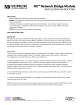
1.1.0.1 View of the SMN
Figure 1-2 View of the FL SWITCH SMN 6TX/2POF-PN
– Diagnostic/status indicators
Important information is displayed directly on the device. Each port has two LEDs. The
top LED always indicates the “LINK”, the display of the bottom LED is set with the func-
tion switch.
– MODE switch for LEDs and Smart mode
The MODE switch can be used to specify which information is displayed by the second
port-specific LED. The three LEDs below the switch indicate the selected mode. This
information is then displayed by all port-specific LEDs (see also example on page 14).
In addition, this button is used to set the switch to Smart mode (for details, see “Using
Smart mode” on page 20).
– Mini-DIN RS-232
RS-232 interface in Mini-DIN format for on-site configuration via the serial interface.
– Signal contact
The floating signal contact can be connected here via a 2-pos. COMBICON connector.
– Supply voltage connection
The supply voltage can be connected via the 4-pos. COMBICON connector (redundan-
cy is optional).
1.1.1 Dimensions of the SMN
Depth from top edge of DIN rail including MEM PLUG: 175 mm


Smart Managed Narrow Switch
8089_en_03 PHOENIX CONTACT 13
1.2 Status and diagnostics indicators
Please note that the meaning of the LEDs differs in Smart mode (see “Using Smart mode”
on page 20).
Des. Color Status Meaning
US1 Green On Supply voltage 1 within the tolerance range
Off Supply voltage 1 too low
US2 Green On Supply voltage 2 within the tolerance range
Off Supply voltage 2 too low
FAIL Red On Signal contact open, i.e., an error has occurred
Off Signal contact closed, i.e., an error has not occurred
A Link LED is located on the front of the SMN for each port
LNK
(Link)
Green On Link active
Off Link not active
An additional LED is located on the front of the SMN for each port. The function of the second LED (MODE) for each port
can be set using the MODE switch (see also example below). There are three options (during the boot process the mode
and port LEDs are permanently on):
ACT
(Activity)
Green On Transmitting/receiving telegrams
Off Not transmitting/receiving telegrams
SPD
(Speed)
Green ON (green) 100 Mbps
Off 10 Mbps if Link LED is active (for RJ45 ports only)
FD
(Duplex)
Green On Full duplex
Off Half duplex
FO
(Fiber Optic)
Orange Off The system reserve of the optical path is >2 dB
Flashing
0.5 Hz
The system reserve of the optical path is between 2 dB and 0 dB
Flashing
2 Hz
The system reserve of the optical path is <0 dB
On Diagnostic alarm
ACT/SPD/FD Yellow Flashing Switch is in Smart mode (see “Using Smart mode” on page 20)

Smart Managed Compact Switch
14 PHOENIX CONTACT 8089_en_03
Example:
In Figure 1-4, the LED indicators have the following meaning:
A: The MODE switch has been used to select duplex mode (FD); the mode LEDs now indi-
cate that port 1 is in full duplex mode.
B: The switch has been used to select the data transmission speed (SPD); the mode LEDs
now indicate that port 1 is operating at 10 Mbps, port 2 is operating at 100 Mbps, port 3 is
operating at 100 Mbps, and port 4 is not operating at all.
Figure 1-4 Example of status indicators
1.2.1 Firmware versions and their functions
Firmware version 1.00 provides the standard switch functions.
MODE
ACT SPD FD
AB

Mounting and installation
8089_en_03 PHOENIX CONTACT 15
2 Mounting and installation
2.1 Mounting and removing the SMN
Mount the SMN on a clean DIN rail according to DIN EN 50022 (e.g., NS 35 ... from Phoenix
Contact). To avoid contact resistance, only use clean, corrosion-free DIN rails. End brack-
ets (E/NS 35N, Order No. 0800886) can be mounted to the right and left of the SMN to stop
the modules from slipping on the DIN rail.
Mounting:
1Place the module onto the DIN rail from above (1). The upper holding keyway of the
module must be hooked onto the top edge of the DIN rail. Push the module from the
front towards the mounting surface (2).
Figure 2-1 Snapping the SMN onto the DIN rail
2Once the module has been snapped on properly, check that it is fixed securely on the
DIN rail. Check whether the positive latch is facing upwards, i.e., snapped on correctly.
Removal:
1Pull down the positive latch using a suitable tool (e.g., screwdriver). Then swivel the
bottom of the module away from the DIN rail slightly (1). Next, lift the module upwards
away from the DIN rail (2).
Figure 2-2 Removing the SMN
1
2
A
1
2

Smart Managed Compact Switch
16 PHOENIX CONTACT 8089_en_03
2.2 Installing the Smart Managed Narrow Switch
2.2.1 Connecting the 24 V DC supply voltage
The SMN is operated using a 24 V DC voltage, which is applied via COMBICON. If required,
the voltage can also be supplied redundantly (see Figure 2-4).
Figure 2-3 Supplying the SMN using one voltage source
Redundant 24 V DC supply
Figure 2-4 Supplying the SMN using two voltage sources
If redundant power supply monitoring is active (default setting), an error is indicated if only
one voltage is applied. A bridge between US1 and US2 prevents this error message.
However, it is also possible to deactivate monitoring in web-based management or via
SNMP.
OUT
24 V DC
US1
GND
US2
GND
R1
R2
In order to reset the SMN on power up, the power supply must be interrupted for at least
3 seconds.
OUT
24 V DC
US1
GND
US2
GND
R1
R2

Mounting and installation
8089_en_03 PHOENIX CONTACT 17
2.2.2 Signal contact
The switch has a floating signal contact. An error is indicated when the contact is opened.
Figure 2-5 Basic circuit diagram for the signal contact
The indicated error states are configured in web-based management or via SNMP. For a list
of error states that can be configured, please refer to Section ““Diagnostics, Alarm Contact”
Menu” on page 44.
2.2.3 Assignment of the RJ45 Ethernet connectors
In the event of a non-redundant voltage supply, the switch indicates the voltage supply
failure by opening the signal contact. This error message can be prevented by connecting
the supply voltage to both terminal blocks in parallel, as shown in Figure 2-3, or by deac-
tivating redundant power supply monitoring in web-based management or via SNMP.
Table 2-1 Pin assignment of RJ45 connectors
Pin number 10Base-T / 10 Mbps 100Base-T / 100 Mbps
1 TD+ (transmit) TD+ (transmit)
2 TD- (transmit) TD- (transmit)
3 RD+ (receive) RD+ (receive)
4- -
5- -
6 RD- (receive) RD- (receive)
7- -
8- -
R1 R2
67842015

Smart Managed Compact Switch
18 PHOENIX CONTACT 8089_en_03
2.2.4 RS-232 interface for external management
The 6-pos. Mini-DIN socket provides a serial interface to connect a local management sta-
tion. It enables the connection to the management interface (for an appropriate cable,
please refer to page 170) via a VT100 terminal or a PC with corresponding terminal emula-
tion. Set the following transmission parameters:
Figure 2-6 Transmission parameters and assignment of the RS-232 interface
2.3 Grounding
All Factoryline devices must be grounded so that any possible interference is shielded from
the data telegram and discharged to ground potential.
A wire of at least 2.5 mm2 must be used for grounding. When mounting on a DIN rail, the
DIN rail must be connected to protective earth ground via grounding terminal blocks. The
module is connected to protective earth ground via the metal header.
Bits per second 38400
Data bits 8
Parity None
Stop bits 1
Flow control None
Grounding protects people and machines against hazardous voltages. To avoid these
dangers, as far as possible, correct grounding, taking the local conditions into account, is
vital.
12
34
56
TxD
RxD
res.
RTSCTS
RS-232 (V.24) interface
6151007

Startup and functions
8089_en_03 PHOENIX CONTACT 19
3 Startup and functions
3.1 Basic settings
3.1.1 Delivery state/default settings
By default upon delivery or after the system is reset to the default settings, the following
functions and properties are available:
– The password is: “private”
– All IP parameters are deleted. The switch has no valid IP parameters:
IP address: 0.0.0.0
Subnet mask: 0.0.0.0
Gateway: 0.0.0.0
– PROFINET is activated as the addressing mechanism.
– All available ports are activated with the following parameters:
- Autonegotiation
- Autocrossing
– All counters of the SNMP agent are deleted.
– The web server, SNMP agent, and RS-232 interface are active.
– Port mirroring, Rapid Spanning Tree, broadcast limiter, and MRP are deactivated.
– The alarm contact only opens in the event of non-redundant power supply.
– The transmission of SNMP traps is deactivated and the switch has no valid trap desti-
nation IP address.
– The aging time is set to 40 seconds.
– The WBM refresh interval is set to 30 seconds.
– The switch is in “PROFINET” mode.
– The transmission of SNMP traps is deactivated and the switch has no valid trap desti-
nation IP address.
The basic Ethernet functions do not have to be configured and are available when the
supply voltage is switched on.
The procedure for switching to the supported operating modes via Smart mode is de-
scribed in Section “Using Smart mode” on page 20.
The aging time is set using the “dot1dTpAgingTime” MIB object (OID 1.3.6.1.2.1.17.4.2).
The available setting range is 10 to 825 seconds. For static configuration, an aging time
of 300 seconds is recommended.

Smart Managed Compact Switch
20 PHOENIX CONTACT 8089_en_03
3.2 Using Smart mode
Smart mode enables the user to change the operating mode of the switch without having
access the management interface.
The FL SWITCH SMN offers the following setting options via Smart mode:
– Reset to the default settings
– Set PROFINET mode
– Exit Smart mode without changes
3.2.1 Activating Smart mode
The mode button is used to call/exit Smart mode and to select the desired setting. The three
mode LEDs indicate the mode that is currently set and the mode which will apply when ex-
iting Smart mode.
3.2.1.1 Calling Smart mode
•Following the switch boot phase, as soon as the three mode LEDs go out, press and
hold down the mode button for more than five seconds. If Smart mode is active, the
three LEDs will flash.
•When Smart mode is started, the switch is initially in the “Exit without changes” state.
3.2.1.2 Selecting the desired setting
•To select the various settings, press the mode button briefly and select the desired op-
erating mode.
3.2.1.3 Exiting Smart mode
•To exit, press and hold down the mode button for at least five seconds. The previously
selected operating mode is saved.
3.2.1.4 Possible operating modes in Smart mode
The FL SWITCH SMN supports the selection of the following operating modes in Smart
mode (see also example below):
Table 3-1 Operating modes in Smart mode
Mode ACT
LED 1
SPD
LED 2
FD
LED 3
Exit Smart mode without changes Off Off On
Reset to the default settings Off On Off
Set PROFINET mode Off On On
/