Page is loading ...

INSTALLING OPTIONAL BIN GUIDES
DESCRIPTION
Bin guides are fences that prevent side-to-side movement of
the bins while traveling down the roller conveyors and are
most often used with smaller bins. They are usually installed
in pairs, spaced slightly wider than the bin width. With proper
conveyor strip spacing, one bin guide can be used between
two bin tracks.
INSTALLATION
1. Bin guides are attached using an
EE
EE--
--ZZ
ZZ
NN
NNUU
UUTT
TT
®on
each end (refer to Figure 9a). Determine proper
spacing for guides and insert
E-Z NUTS
through
slots in rails. NOTE:
For best results, bin guides must be installed
parallel with conveyor strips.
2. Finger tighten the bolts making sure the
E-Z NUTS
turn within the rail for a firm grip. Fully tighten bolts
when guides are properly positioned.
3. Test by placing bins on cart and reposition conveyor
strips and guides for best results.
DESCRIPTION
The
SS
SSuu
uupp
pppp
ppll
llyy
yy
‘‘
‘‘nn
nn
RR
RRee
eett
ttuu
uurr
rrnn
nn
Gravity Feed Cart provides a
mobile parts bin supply system with two levels of gravity feed
conveyors sloping toward the workplace and one bin return
conveyor sloping toward the aisle. Slope of all levels of con-
veyors can be adjusted for optimum performance with various
sizes and weights of bins. Bin boxes are not included.
Optional side guides can be added to stabilize bins on con-
veyors. Maximum rated capacity is 300 lbs.
NOTE:
Prior to assembly, become familiar with the following
instructions and names of components.
ASSEMBLY
1. Locate four angle brackets and two 48" aluminum
frame members. Place two 48" aluminum frame
members on floor with large slot down. Affix angle
brackets to frame members members by sliding
clamp plates into aluminum rails. Position as shown
in Figure 1, and tighten track nuts to secure.
ASSEMBLY INSTRUCTIONS
SS
SSuu
uupp
pppp
ppll
llyy
yy
‘‘
‘‘nn
nn
RR
RRee
eett
ttuu
uurr
rrnn
nn
TM
GRAVITY FEED CART
Printed in USA Bulletin No. 630436.a
P.O. Box 26 • 600 South Clark St.
Mayville, WI 53050
Phone 920–387–5195
HUBBELL
®
Workplace Solutions
IMPORTANT
ASSEMBLY NOTES
1. Components are assembled
using the Hubbell Workplace
Solutions “ALIGN – SET –
TIGHTEN” system. Brackets
are clamped to aluminum
extrusions with track nuts
(single bolt) or clamp bars (two
bolts) inside one of the two
cavities. Always install single
bolt track nuts with widest
dimension perpendicular to
aluminum rail.
2. All main frame
members are
extruded aluminum
rail. Install with
large cavity down.
3. Shelf, coil holders, bin bar and
all brackets are steel and
shipped with assembly
hardware (usually track nuts)
installed. Some
track nuts may have to be
reversed (bolt head on
opposite side of plate) for
proper assembly.
12. Install stop/guard brackets onto uprights of frame.
Slide brackets onto uprights from top (Fig. 10). The
top of stop brackets should be positioned 0.75"
ABOVE the end rollers on the low end. The top of
the guard brackets should be positioned 0.0625"
BELOW the end rollers on the high end.
NOTE:
Stop brackets and guard brackets are identical.
Stop brackets are used on the LOW end of the
conveyor strips to provide bin stops.
Guard brackets are installed on the HIGH end of the
strips to prevent injury to people using the cart.
13. Install end caps on the top of uprights and on each
end of 48" base rails.
14. Check to make sure all bolts are tight and that unit
is square (all four casters firmly on floor).
Adjust as necessary.
15. Test by placing loaded bins on cart, allowing them to
roll down against stop. Adjust spacing of conveyor
strips and, if required, increase or decrease
conveyor slope by raising or lowering cross rails to
obtain optimal performance with bin sizes and loads
to be used.
Figure 10.
INSTALLING STOP/GUARD BRACKETS
Figure 11.
INSTALLING OPTIONAL BIN GUIDES
GUARD
BRACKET
STOP BRACKET
48" ALUMINUM
RAILS
ANGLE
BRACKETS
ANGLE BRACKETS
FLUSH WITH ENDS
OF RAILS
SECURELY
TIGHTEN
CLAMP BOLTS
Figure 1.
ASSEMBLING BASE RAILS
BIN GUIDE REAR
CROSS
RAIL
STOP
BRACKET
GUARD
BRACKET
ROLLER
CONVEYOR
STRIP
FRONT
CROSS
RAIL

2. Assemble four 42.38" long uprights to angle
brackets on base rails as shown in Fig. 3. Wrench
tighten to secure.
7. Install cross rails from Step 5 by sliding brackets
down uprights until bottom of brackets are on marks
made in Step 6. Finger tighten bolts to hold on
marks (Fig. 7).
8. Push side frames together tight against cross rails
(uprights 44" o.c.) and fully tighten all bolts.
9. Tip assembled frame on
its side and install
casters (Fig. 8). Secure
with wrench supplied.
10. Stand frame upright.
Mark cross rails with
desired spacing of roller
conveyors, Six on each
level. Consider the size
and type of bins which
will be used on the cart.
11. Install the roller conveyor sections on the cross
rails by inserting the
EE
EE--
--ZZ
ZZ
NN
NNUU
UUTT
TT
®into the slot in the
rail, aligning the conveyor with the mark, and finger
tightening the bolt while making sure the
E-Z NUT
turns in the rail for maximum grip. Ensure conveyor
channel ends are equal distance from cross rails
(conveyor centered on rails). Fully tighten bolts
when conveyor sections are properly placed
(See Figures 9 & 9a).
6. Mark heights for other four cross rails on uprights
both side frames with (Fig 6). Note that top two
cross rails on front uprights are installed lower
than corresponding cross rails on back
uprights so that bins will roll to front on roller
conveyors. Bottom cross rails (already installed)
are higher at front to facilitate bin return (Fig. 6a).
NOTE: Slope and spacing of roller con-
veyors may be adjusted for optimal per-
formance following assembly.
3. Locate one right-hand and one left-hand framing
bracket. Slide framing brackets onto side frame
uprights on one side frame assembly as shown in
Figure 3. Position as shown and tighten. Repeat
for other side frame assembly.
NOTE:
“Right hand” and “Left hand” sub-assemblies
are required. Make side frames “mirror images”.
4. Join left and right side frames by standing
assemblies upright with two 42.38" rails. Slide rails
onto framing brackets with rails ends tight against
side frame uprights. Tighten securely. (Fig. 4).
5. Locate remaining four 42.38" long cross rails,
four left hand framing brackets and four right hand
framing brackets. Assemble framing brackets to
cross members. Finger tighten (Fig. 5).
Figure 2.
ASSEMBLING SIDE FRAMES
48" BASE
RAIL
SIDE UPRIGHTS ONTO
ANGLE BRACKETS WITH
CLAMP PLATE INSIDE RAIL
ANGLE
BRACKET
42.38" LONG
UPRIGHTS
Figure 4.
JOINING SIDE FRAMES
Figure 7.
INSTALLING CROSS RAILS
Figure 9.
ATTACHING CONVEYORS
Figure 9a.
E-Z NUT DETAIL
Figure 5.
ASSEMBLING CROSS MEMBERS
Figure 6.
MARKING CROSS RAIL LOCATIONS
Figure 6a.
32.0"
30.5"
44" o.c.
ref.
18.5"
MARK HEIGHT
ON BOTH RIGHT
AND LEFT SIDE.
CONVEYOR
SECTIONS
CART FRAME
42.38" ALUMINUM CROSS
RAIL ASSEMBLE WITH
LARGE SLOT DOWN
42.38" ALUMINUM CROSS
RAIL. ASSEMBLE WITH
LARGE SLOT DOWN
COMPLETED LEFT
SIDE FRAME
ASSEMBLY FROM
STEP 4
COMPLETED RIGHT
SIDE FRAME
ASSEMBLY FROM
STEP 4
1.125"
2.25"
Figure 3.
ASSEMBLING SIDE FRAMES
SIDE FRAME
FROM STEP 2
RIGHT HAND
FRAMING
BRACKET
FRAMING
BRACKETS
LEFT HAND
FRAMING
BRACKET
RIGHT HAND
FRAMING
BRACKET
LEFT HAND
FRAMING
BRACKET
LEFT HAND SIDE FRAME.
RIGHT HAND SIDE FRAME
OPPOSITE (MIRROR IMAGE)
FRONT
FRONT
FRONT
SLIDE BRACKETS
DOWN TO MARKS
FRONT
BACK
FEED
RETURN
Figure 8
INSTALLING
CASTERS
SWIVEL CASTER
WITH TRACK NUT
CASTER
WRENCH
E-Z NUT GOES
THROUGH SLOT IN
RAIL...TURNS TO LOCK
CONVEYOR
CHANNEL
17.0"

INSTALLING OPTIONAL BIN GUIDES
DESCRIPTION
Bin guides are fences that prevent side-to-side movement of
the bins while traveling down the roller conveyors and are
most often used with smaller bins. They are usually installed
in pairs, spaced slightly wider than the bin width. With proper
conveyor strip spacing, one bin guide can be used between
two bin tracks.
INSTALLATION
1. Bin guides are attached using an
EE
EE--
--ZZ
ZZ
NN
NNUU
UUTT
TT
®on
each end (refer to Figure 9a). Determine proper
spacing for guides and insert
E-Z NUTS
through
slots in rails. NOTE:
For best results, bin guides must be installed
parallel with conveyor strips.
2. Finger tighten the bolts making sure the
E-Z NUTS
turn within the rail for a firm grip. Fully tighten bolts
when guides are properly positioned.
3. Test by placing bins on cart and reposition conveyor
strips and guides for best results.
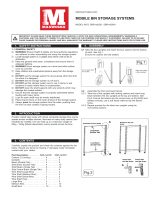
DESCRIPTION
The
SS
SSuu
uupp
pppp
ppll
llyy
yy‘‘
‘‘nn
nnRR
RRee
eett
ttuu
uurr
rrnn
nn
Gravity Feed Cart provides a
mobile parts bin supply system with two levels of gravity feed
conveyors sloping toward the workplace and one bin return
conveyor sloping toward the aisle. Slope of all levels of con-
veyors can be adjusted for optimum performance with various
sizes and weights of bins. Bin boxes are not included.
Optional side guides can be added to stabilize bins on con-
veyors. Maximum rated capacity is 300 lbs.
NOTE:
Prior to assembly, become familiar with the following
instructions and names of components.
ASSEMBLY
1. Locate four angle brackets and two 48" aluminum
frame members. Place two 48" aluminum frame
members on floor with large slot down. Affix angle
brackets to frame members members by sliding
clamp plates into aluminum rails. Position as shown
in Figure 1, and tighten track nuts to secure.
ASSEMBLY INSTRUCTIONS
SS
SSuu
uupp
pppp
ppll
llyy
yy‘‘
‘‘nn
nnRR
RRee
eett
ttuu
uurr
rrnn
nn
TM
GRAVITY FEED CART
Printed in USA Bulletin No. 630436.a
600 South Clark St.
Mayville, WI 53050
Phone 920–387–4120
HUBBELL
®
Workplace Solutions
IMPORTANT
ASSEMBLY NOTES
1. Components are assembled
using the Hubbell Workplace
Solutions “ALIGN – SET –
TIGHTEN”system. Brackets
are clamped to aluminum
extrusions with track nuts
(single bolt) or clamp bars (two
bolts) inside one of the two
cavities. Always install single
bolt track nuts with widest
dimension perpendicular to
aluminum rail.
2. All main frame
members are
extruded aluminum
rail. Install with
large cavity down.
3. Shelf, coil holders, bin bar and
all brackets are steel and
shipped with assembly
hardware (usually track nuts)
installed. Some
track nuts may have to be
reversed (bolt head on
opposite side of plate) for
proper assembly.
12. Install stop/guard brackets onto uprights of frame.
Slide brackets onto uprights from top (Fig. 10). The
top of stop brackets should be positioned 0.75"
ABOVE the end rollers on the low end. The top of
the guard brackets should be positioned 0.0625"
BELOW the end rollers on the high end.
NOTE:
Stop brackets and guard brackets are identical.
Stop brackets are used on the LOW end of the
conveyor strips to provide bin stops.
Guard brackets are installed on the HIGH end of the
strips to prevent injury to people using the cart.
13. Install end caps on the top of uprights and on each
end of 48" base rails.
14. Check to make sure all bolts are tight and that unit
is square (all four casters firmly on floor).
Adjust as necessary.
15. Test by placing loaded bins on cart, allowing them to
roll down against stop. Adjust spacing of conveyor
strips and, if required, increase or decrease
conveyor slope by raising or lowering cross rails to
obtain optimal performance with bin sizes and loads
to be used.
Figure 10.
INSTALLING STOP/GUARD BRACKETS
Figure 11.
INSTALLING OPTIONAL BIN GUIDES
GUARD
BRACKET
STOP BRACKET
48" ALUMINUM
RAILS
ANGLE
BRACKETS
ANGLE BRACKETS
FLUSH WITH ENDS
OF RAILS
SECURELY
TIGHTEN
CLAMP BOLTS
Figure 1.
ASSEMBLING BASE RAILS
BIN GUIDE REAR
CROSS
RAIL
STOP
BRACKET
GUARD
BRACKET
ROLLER
CONVEYOR
STRIP
FRONT
CROSS
RAIL
/