Lokar Cable Operated Sensor Kit Installation guide

Category
Car alarm
Type
Installation guide

Lokar Cable Operated Sensor Kit is a versatile device designed for Ford AOD, 4R70W, and AODE transmissions, providing accurate gear position sensing for various automotive applications. It features a sturdy adjustable cable mounting bracket for precise sensor positioning, ensuring compatibility with different transmission selector shafts. The kit includes a sensor bracket for direct transmission mounting or a universal mounting bracket for remote installation, offering flexible mounting options.

Lokar Cable Operated Sensor Kit is a versatile device designed for Ford AOD, 4R70W, and AODE transmissions, providing accurate gear position sensing for various automotive applications. It features a sturdy adjustable cable mounting bracket for precise sensor positioning, ensuring compatibility with different transmission selector shafts. The kit includes a sensor bracket for direct transmission mounting or a universal mounting bracket for remote installation, offering flexible mounting options.

Building American Quality… With A Lifetime Warranty!
TOLL FREE 1-877-469-7440 • [email protected] • www.lokar.com
®
Cable Operated Sensor Kit Installation Instructions
For Ford AOD, 4R70W, and AODE
With New Style Decoder Box
Cable Operated Sensor Kit Installation Instructions
For Ford AOD, 4R70W, and AODE
With New Style Decoder Box
INS0236 Rev. 08/23/2023Page 1
© 2023 Lokar, Inc.
General Installation Notes:
Please read these instructions completely before beginning the
installation. If you have any questions, please call.
Before beginning the installation, disconnect the negative battery
cable and use wheel chocks to block the vehicle's wheels. Do not
attempt to install this product while the engine is running.
Make sure the engine, transmission, and frame are properly
grounded. We recommend applying anti-seize lubricant to all
aluminum threads before final assembly.
All Lokar Installation Instructions can be found by visiting
www.lokar.com/instructions.html.
Refer to Fig. 1, 2 and 3 for the component names.
NOTE: There are two styles of decoder boxes: OLD and NEW. See
Fig. 3 to determine which type you have. If you have the OLD style
decoder box, these are NOT the correct instructions. You need
instructions # INS0039, which can be found on the Lokar website or
can be emailed to you by contacting Lokar Technical Support.
MOUNTING OPTIONS: The Lokar Cable Operated Sensor
Kit is equipped to mount the sensor either on the passenger
side of the transmission using the sensor bracket, or in a
remote location within 5 feet of the transmission selector
shaft using the provided universal mounting bracket.
To mount the sensor remotely inside the vehicle, a
Lokar Remote Mounting Cable Kit (part # CINR-1796) will
be required. This extends the cable 7 feet, for a total of
12 feet.
The decoder box should always be mounted inside the
vehicle and out of the elements.
Step 1: Assemble the upper and lower parts of the
adjustable cable mounting bracket by installing two
#8-32 x 5/16" button head screws and lock washers
using a 5/32" Allen wrench. Do not fully tighten
the screws yet. The orientation of the upper part of
the adjustable cable mounting bracket will depend
on the orientation of the trans arm on your selector
shaft. See Fig. 4.
Fig. 1Fig. 1
Wiring
Harness
Universal
Mounting
Bracket
#8-32 x 5/16"
Flat Head Phillips
Screws
Sensor
Bracket
Spacers
AOD
Indicator
Arm
Index Cable
Stop
(with Set Screw)
Adjustable Cable
Mounting Bracket (lower)
#8-32 x 5/16"
Button Head Screws
with Lock Washers
Adjustable Cable
Mounting Bracket
(upper)
Inner Wire Adjuster Nut Cable Housing
Spacer
Flat Washer
5/16" Lock
Washer
M8 x 30mm
Hex Head Bolt
Flat Washers
5/16" Lock Washers
M8 x 30mm Hex Head Bolts Neutral Safety Relay
Sensor
Spring
Cable Housing
#8-32 x 5/16" Button
Head Screws with
Lock Washers
Fig. 3Fig. 3
Decoder BoxesDecoder Boxes
OLD StyleOLD Style
NEW StyleNEW Style
Fig. 2Fig. 2
Index Cable Stop
(with Set Screw)
Page 2 INS0236 Rev. 08/23/2023
Step 2: Remove the second pan bolt to the rear of the selector shaft. Install the
adjustable cable mounting bracket there using the provided M8 x 30mm hex
head bolt, lock washer, flat washer, and spacer. Fig. 5 and Fig. 6
NOTE: If you have an aluminum transmission pan, the spacer may
not be required.
Step 3: Remove the sensor cap by removing the two #10-24 x 1/2" flat head screws
using a 1/8" Allen wrench, and separate the cable housing from the sensor. Fig. 7
Step 4: Make sure the sensor arm is parallel to the slot in the sensor shaft, with
the set screw in the top of the sensor arm aligned with the slot. If it is not,
loosen the set screw in the top of the sensor arm using a 1/16" Allen
wrench, and adjust the position of the sensor arm on the shaft. Fig. 8
Step 5: This step varies, depending on where you are mounting the sensor as
described below:
Directly onto the passenger side of the transmission: Use the
provided M8 x 30mm hex head bolts, lock washers, flat washers, and
spacers to mount the sensor and sensor bracket to the first and second
pan bolt to the rear of the dipstick tube. NOTE: If you have an aluminum
transmission pan, the spacers may not be required.
Adjust the sensor and sensor bracket forward or backward until you can
move the sensor arm through its full range of travel without the sensor
arm interfering with the transmission case. Tighten the M8 x 30mm hex
head bolts that are used to mount the sensor bracket. Fig. 9
In a remote location: Make sure the sensor is close enough that the
cable housing can be routed into the back side of the adjustable cable
mounting bracket. Install the universal mounting bracket onto the vehicle
using the two smaller holes in the bracket and your choice of fasteners
(not included). The small holes in the universal mounting bracket may be
drilled out larger if needed. Once the bracket is installed in the remote
location, remove the sensor from the other sensor bracket. Install the
sensor onto the universal mounting bracket, using the #8-32 x 5/16" flat
head Phillips screws. There are two pairs of countersunk holes on the
universal mounting bracket and three holes in the sensor to allow for
different mounting positions.
Fig. 4Fig. 4 Fig. 5Fig. 5 Fig. 6Fig. 6
© 2023 Lokar, Inc.
Fig. 7Fig. 7
Flat WasherFlat Washer
Flat Flat
Washer Washer
and Lock and Lock
WasherWasher
Selector Selector
ShaftShaft
Selector Selector
ShaftShaft
Lock WasherLock Washer
Spacer Spacer
(above (above
bracket)bracket)
Spacer Spacer
(above (above
bracket)bracket)
M8 x 30mm M8 x 30mm
Hex Head BoltHex Head Bolt
Adjustable Cable Adjustable Cable
Mounting BracketMounting Bracket Adjustable Cable Adjustable Cable
Mounting BracketMounting Bracket
M8 x 30mm
Hex Head Bolt
Trans Arm
Pointed Down
Adjustable Cable
Mounting Bracket
With Trans Arm
Pointed UP
Adjustable Cable
Mounting Bracket
With Trans Arm
Pointed DOWN
Inner Wire Cable Housing
Trans Arm Trans Arm
Pointed UpPointed Up
Hole for Indicator Hole for Indicator
ConnectionConnection
Hole for Indicator Hole for Indicator
ConnectionConnection
Sensor Cap
Sensor Housing
Sensor Arm
End of Cable
Housing Groove
#10-24 x 1/2"
Flat Head
Screws
Step 6: This step also varies depending on what selector shaft is
installed in the transmission.
With a Lokar selector shaft: The trans arm has a 3/16" diameter
hole in it for the indicator cable to connect to. Make sure that
this hole is to the rear of the slot in the trans arm. If it is not,
remove the trans arm and re-install it with the 3/16" hole to the
rear of the slot in the trans arm. Fig. 5 and Fig. 6
With any type of selector shaft EXCEPT a Lokar selector
shaft: Install the AOD indicator arm onto the trans arm. The
open part of the "J" shape in the AOD indicator arm should
face away from the selector shaft. Fig. 10
Step 7: Remove the inner wire from the cable housing. Temporarily
install the threaded end of the cable housing into the adjustable
cable mounting bracket and secure it with the adjuster nut.
The cable is designed to be cut-to-fit. Route the cable housing
from the adjustable cable mounting bracket to the sensor.
There is a groove in the sensor housing that the end of the cable
housing fits in to. Mark the cable housing at the end of the cable
housing groove. Remove the cable housing from the adjustable
cable mounting bracket. Fig. 7 and Fig. 8
Step 8: Make sure the inner wire has been removed from the
cable housing. Wrap tape around the area to be cut and use
a cutoff wheel or fine-toothed hacksaw to cut the cable housing
at your mark. You also may use heavy duty 8" diagonal cutting
pliers. Lokar recommends Klein brand Diagonal Cutting Pliers,
# D2000-28 available at The Home Depot or through W. W.
Graingers, Part # 4A838.
Before moving forward, make sure the end of the cable
housing that you just cut is open and the inner wire will slide in
without interference.
Step 9: Remove the sensor from the sensor bracket using a 5/32" Allen
wrench. Reattach the cable housing to the sensor by clamping
it between the sensor housing and the sensor cap, making sure
the cable housing does not extend beyond the end of the cable
housing groove in the sensor housing. Secure the sensor cap
using the #10-24 x 1/2" flat head screws you removed earlier.
Then, install the threaded end of the cable housing back into
the adjustable cable mounting bracket.
Step 10: Slide the inner wire into the cable housing until it is protruding
from both ends. Put the spring on the inner wire between the
sensor arm and the sensor cap.
Install the index cable stop into the sensor arm with the
cable hole between the sensor arm and the sensor. Slide the
inner wire through the index cable stop, so that at least 1" is
protruding beyond the index cable stop. Make sure the inner
wire is on the correct side of the sensor arm. Fig. 11
Step 11: Reinstall the sensor onto the sensor bracket using the #8-32 x 5/16"
button head screws and lock washers (transmission mounted
sensor bracket) or the #8-32 x 5/16" flat head Phillips screws
(universal mounting bracket).
Step 12: At the opposite end of the cable, install the index cable stop
into the trans arm or the AOD indicator arm. Slide the inner wire
through the hole in the index cable stop so that approximately
1" is protruding. You should now have excess inner wire at the
opposite end of the cable (at the sensor).
There is a set screw in the hex end of the index cable stop on
the trans arm or the AOD indicator arm. Tighten the set screw
using a 1/16” Allen wrench. Adjust the angle of the adjustable
cable mounting bracket so that the inner wire will not bind or
kink as it goes through the gear selections. Fig. 12 and Fig. 13
Note: It is very important that the cable housing is secured.
Fasten the cable housing tightly so there is no slack or
movement in the cable housing.
Step 13: Make sure the transmission is in Park.
All applications with the trans arm pointing UP: Push the
sensor arm up against the spring, so that the spring
is compressed approximately 1/8" at rest in Park. Fig.
14 While holding that position, tighten the set screw that is
installed in the index cable stop on the sensor arm using a
1/16" Allen wrench.
All applications with the trans arm pointing DOWN:
Push the sensor arm as far as it will go until the spring
is completely compressed. Then, let the spring expand
approximately 1/8". Fig. 15 While holding that position,
tighten the set screw that is installed in the index cable stop
on the sensor arm using a 1/16" Allen wrench.
Step 14: Trim the excess inner wire, leaving about 1” protruding. Shift
the transmission from Park, one gear at a time, and check each
gear to make sure the arm on the sensor does not hit anything
and the sensor does not bottom out on its internal stops. The
sensor arm does not need to be the same distance from the
stops in Park as it is in low gear. If the sensor bottoms out on its
internal stop before the shifter reaches first gear, loosen up one
end of the inner wire at either of the index cable stops and move
the trans arm/AOD indicator arm or sensor arm. Make sure you
maintain at least 1/8” or more of compression on the spring
at the sensor end of the cable when the transmission is in
Park (applications with the trans arm pointed up) or Low
gear (applications with the trans arm pointed down).
Once the sensor is operating properly and no more adjustments
need to be made, cut the excess inner wire within 1/2” of the
index cable stop on both ends of the cable.
Mounting The Decoder Box
The decoder box must be mounted in a dry place. When mounting
this unit, keep it within reach of the wires on the LED display and the
sensor. The decoder box can be mounted with two screws or double-
sided tape. Be sure it is still accessible for connecting the wiring and for
programming later.
Page 3 INS0236 Rev. 08/23/2023
© 2023 Lokar, Inc.
Fig. 8Fig. 8
Fig. 9Fig. 9
Fig. 10Fig. 10 Fig. 11Fig. 11
Spring
Cable Housing
Sensor Arm
Index Cable
Stop
(with Set Screw)
Inner Wire
Sensor Arm
Sensor Sensor
BracketBracket
M8 x 30mm Hex Head Bolts M8 x 30mm Hex Head Bolts
With Lock Washers, Flat With Lock Washers, Flat
Washers, and SpacersWashers, and Spacers
AOD Indicator AOD Indicator
ArmArm
SensorSensor
Slot in Sensor
Shaft is Parallel to
Sensor Arm
Set Screw
End of Cable
Housing Groove
INS0236 Rev. 08/23/2023
Page 4
© 2023 Lokar, Inc.
Fig. 13Fig. 13Fig. 12Fig. 12
Index Cable StopIndex Cable Stop
(with Set Screw)(with Set Screw)
Index Cable StopIndex Cable Stop
(with Set Screw)(with Set Screw)
Trans Arm Trans Arm
Pointed UpPointed Up
Trans Arm Trans Arm
Pointed DownPointed Down
Inner WireInner Wire
Fig. 14Fig. 14 Fig. 15Fig. 15
Spring compressed Spring compressed
approximately 1/8" at restapproximately 1/8" at rest Spring expanded Spring expanded
approximately 1/8" at restapproximately 1/8" at rest
(Sensor removed from transmission for photo)
Applications With Trans Arm Pointed UP Applications With Trans Arm Pointed DOWN
(Sensor removed from transmission for photo)
Page 5
© 2023 Lokar, Inc.
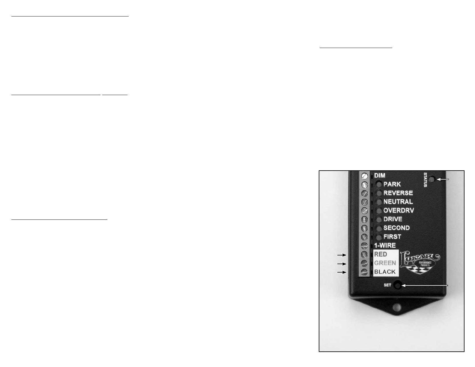
Wiring The Sensor and The Decoder Box
The sensor has a 10 foot long cable attached to it. This cable contains
three wires which connect to the decoder box: one red, one green or
white, and one black. To connect the wires to the decoder box, use a
small flat blade screwdriver to loosen the screw terminal. Strip 3/8” of the
insulation off of each of the wires. Connect the red wire to the terminal
marked RED. Connect the green or white wire to the terminal marked
GREEN. Connect the black wire to the terminal marked BLACK. Fig. 16
NOTE: The red, green or white, and black wires on the sensor
should ONLY be connected to the terminals marked RED”,
GREEN”, or BLACK” on the decoder box. DO NOT connect any
of these three wires to the IGNITION+” or GROUND-” terminals
on the decoder box.
Wiring a Lokar Three-Wire LED Indicator
Locate a fused (15A), switched 12V + power source that supplies
power when the ignition key is in the “ON” or “RUN” position, but does
not supply power when the key is off. (NOTE: If you are going to
use the optional Neutral Safety Relay discussed later, this wire
will also need to supply power while the key is in the START”
position.) Run a red wire (not supplied) from that power source to the
decoder box. Join the end of that wire to the end of the red wire from the
LED indicator. Insert the joined end of those wires into the “IGNITION+”
terminal on the decoder box and tighten the terminal screw.
Connect one end of a black wire (not supplied) to a solid chassis
ground. Join the other end of that wire to the black wire from the LED
indicator. Insert the joined end of those wires into the “GROUND-”
terminal on the decoder box and tighten the terminal screw. Fig. 16
NOTE: When you are finished with this step, there will be two (2)
wires connected to the IGNITION+” terminal on the decoder box,
and two (2) wires connected to the GROUND-” terminal on the
decoder box.
If installing a Lokar Three-Wire LED Indicator, DO NOT connect
the remaining green or white wire from the LED Indicator to the
decoder box until you have programmed the gear positions.
Programming The Gear Positions
Programming is done using the push-button SET switch on the top of
the decoder box and watching the programming LED’s located next to
each gear position designation on the decoder box.
NOTE: For the programming procedures below, you will be
watching the LEDs on the decoder box, NOT on the Boot Indicator
or Dash Indicator.
The programming sequence must be completed without interruption
for the settings to be saved. If you stop or turn the key off at any
point during the programming sequence, you will have to start
over from the beginning.
Step 1: Place the transmission in Park and make sure the key is off.
Reconnect the negative battery cable.
Step 2: Press and hold the set switch. Fig. 16 Turn the ignition key on
while holding the set switch down. Then, release the set switch.
Step 3: The programming lights will come on either all green or all
red, except for the STATUS light which will be red. All green
means the decoder box is currently set for ground (-) outputs,
which is correct for a Lokar indicator. If you are using a Lokar
indicator and your programming lights are green at this point
(except for the STATUS light), proceed to Step 4.
Step 3, continued: If the lights are all red, that means the decoder
box is currently set for positive (+) outputs, which some other
brands of indicators use. If your lights are all red and you are
using a Lokar indicator, press and release the set switch. This
will change the mode of the decoder box to ground (-)
outputs.
The programming lights will turn green, and you can then
proceed to Step 4.
If you are using an indicator from another manufacturer,
determine if your indicator requires ground (-) outputs or
positive (+) outputs. Press and release the set switch if needed
to put the decoder box in the correct mode for the other
manufacturer's indicator. Follow the instructions provided with
the other manufacturer's indicator.
Step 4: Press and hold the set switch for approximately 3 seconds
until all of the programming lights turn off, to save the output
setting and put the decoder box in programming mode. Then,
release the set switch. For a Lokar Indicator, the PARK light
should be flashing green.
If at any point in the programming the STATUS light starts flashing
red and green, that means the sensor is not moving.
Step 5: Press and hold the set switch for approximately 3 seconds,
until the PARK light remains on steady.
Step 6: Release the set switch. The PARK light will turn off, and the
REVERSE light should begin flashing.
Step 7: Shift the transmission to Reverse.
Step 8: Press and hold the set switch for approximately 3 seconds,
until the REVERSE light remains on steady.
Step 9: Release the set switch. The REVERSE light will turn off, and
the NEUTRAL light should begin flashing.
Step 10: Shift the transmission to Neutral.
Step 11: Press and hold the set switch for approximately 3 seconds,
until the NEUTRAL light remains on steady.
Step 12: Release the set switch. The NEUTRAL light will turn off, and
the OVERDRIVE light should begin flashing.
Step 13: Shift the transmission to Overdrive.
Step 14: Press and hold the set switch
for approximately 3 seconds,
until the OVERDRIVE light remains on steady.
Step 15: Release the set switch. The OVERDRIVE light will turn off
and the DRIVE light should begin flashing.
Step 16: Shift the transmission to Drive.
Step 17: Press and hold the set switch for approximately 3 seconds,
until the DRIVE light remains on steady.
Step 18: Release the set switch. The DRIVE light will turn off, and the
SECOND light should begin flashing.
Step 19: Press and release the set switch. The SECOND light will turn
off and the FIRST light should begin flashing.
Step 20: Shift the transmission to First.
Step 21: Press and hold the set switch
for approximately 3 seconds,
until the FIRST light remains on steady.
Step 22: Release the set switch. The FIRST light will turn off and the
STATUS light will begin flashing red.
Step 23: Press and hold the set switch
for approximately 3 seconds,
until the STATUS light turns off. Release the set switch. The
FIRST light should be on steady and the STATUS light should
be steady green.
Set
Switch
Fig. 16Fig. 16
Status
Light
Insert
sensor
wires
here
Step 24: Shift the transmission through each of the gears to verify that
the programming lights match correctly.
Step 25: Following the wiring diagram in Fig. 17, connect the rest of the
wires from the LED indicator to the decoder box.
Changing the LED Colors
Step 1: To enter the color setup mode, put the transmission in Park and turn
the ignition key to ON, but do not start the engine.
Step 2: With the ignition ON, press and hold the SET switch on the
decoder box until the PARK LED on the decoder box turns off
(approximately two seconds).
Step 3: Release the SET switch. Both the STATUS and PARK LEDs on
the decoder box should now be flashing.
Step 4: The PARK position on the indicator will now be lit with the current
color setting for PARK. To change the color, tap the SET switch (less
than one second). The PARK position on the indicator will cycle to
the next color. Continue tapping the SET switch until the PARK
position on the indicator is lit with the desired color.
Step 5: Once the PARK position on the indicator is lit with the desired
color, press and hold the SET switch until the STATUS and
PARK LEDs on the decoder box stop flashing (approximately two
seconds). The color for PARK is now stored.
Step 6: Release the SET switch. The STATUS and REVERSE LEDs
on the decoder box will now be flashing, and the REVERSE
position on the indicator will be lit with the current color setting
for REVERSE.
INS0236 Rev. 08/23/2023
NOTE: Some indicator sensors come with
a white wire instead of a green wire. If
your sensor has a white wire, connect it
to the terminal labeled GREEN.
INS0236 Rev. 08/23/2023Page 6
© 2023 Lokar, Inc.
Step 7: Follow the above procedure for each of the gear positions, tapping
the SET switch to cycle through to the desired color on the
indicator, holding the SET switch to save the setting, and
releasing the SET switch to advance to the next gear position.
Step 8: Once the color for all gear positions has been programmed, the
STATUS LED should be the only one on and flashing on the
decoder box, and the PARK position on the indicator should be on.
Step 9: Tapping the SET switch (less than one second) will now cycle
through eight intensity settings on the indicator. Watch the
PARK position on the indicator, and when the desired intensity
is found, press and hold the SET switch until the STATUS LED
stops blinking (approximately two seconds). The intensity for
the indicator is now set.
Step 10: Release the SET switch. The decoder box has now exited the
setup mode.
Optional Features and Wiring
NOTE: You must complete the "Programming the Gear Positions"
section before connecting the wiring for any of the "OPTIONAL"
sections below.
OPTIONAL: Connecting The Neutral Safety Relay
If your vehicle already has a neutral safety switch in the wiring harness
to prevent the vehicle from starting while it is in gear, then you do not
need to use the neutral safety switch feature in the decoder box, and
you will not need to connect this relay.
If your vehicle does not already have a neutral safety switch, cut the
wire that goes from your starter switch to the starter solenoid. Connect
the wire from the ignition switch to the GREEN wire from the relay,
and connect the BLACK wire from the relay to the wire going to the
starter solenoid. For wiring harnesses which provide wires for the
neutral safety relay, connect one side to the GREEN wire and the other
side to the BLACK wire.
The WHITE wire from the relay connects to the "SAFETY" terminal on
the decoder box. The RED wire connects to the power wire for the
decoder box. For the neutral safety switch to operate properly, the
"IGNITION+" terminal on the decoder box must have power when the
key is in the "START" position. Fig. 18
OPTIONAL: Connecting The Park/Neutral Signal To An ECM
If your vehicle is fuel injected and the ECM requires a signal when the
transmission is in either Park or Neutral, the neutral safety terminal on
the decoder box can be used. The "SAFETY" terminal provides a ground
when the transmission is in Park or Neutral. This can be connected to
the ECM in order to pass vehicle inspection. The "SAFETY" terminal can
be used for both a neutral safety and an ECM signal at the same time.
OPTIONAL: Connecting Backup Lights To The Decoder Box
If your vehicle already has a backup light switch, then you do not need
to connect anything to the "BACKUP" terminal. If you do not have a
backup light switch and will be using backup lights on your vehicle,
then connect the hot side of the backup lights to the terminal marked
"BACKUP". This circuit is designed to supply up to 15 amps.
OPTIONAL: Enabling the Indicator's "DIM" Function
If you want the Indicator's LEDs to dim at night, locate a wire or
terminal that only has power when your parking lights or headlights are
on. Connect a wire from that wire or terminal to the "DIM" terminal on
the decoder box.
TYPE OF INDICATOR SYSTEM
PARK REVERSE NEUTRAL OVERDRV DRIVE SECOND FIRST 1-WIRE
LOKAR 3-WIRE
INDICATOR NOT USED NOT USED NOT USED NOT USED NOT USED NOT USED NOT USED GREEN OR
WHITE WIRE
LOKAR 6-WIRE
INDICATOR
PURPLE
WIRE
YELLOW
WIRE
BLUE
WIRE
BROWN
WIRE
ORANGE
WIRE NOT USED WHITE
WIRE NOT USED
INDIVIDUAL BULBS RED WIRE (+) RED WIRE (+) RED WIRE (+) RED WIRE (+) RED WIRE (+) RED WIRE (+) RED WIRE (+) NOT USED
STR
SYSTEM
PARK
TERMINAL
REVERSE
TERMINAL
NEUTRAL
TERMINAL
OVERDRV
TERMINAL
DRIVE
TERMINAL
SECOND
TERMINAL
FIRST
TERMINAL NOT USED
DGS-1 GREEN WIRE
(+)
GRAY WIRE
(+)
PURPLE WIRE
(+)
YELLOW
WIRE (+)
ORANGE
WIRE (+)
BLUE WIRE
(+)
BROWN WIRE
(+) NOT USED
DGS-2 GREEN WIRE
(+)
GRAY WIRE
(+)
PURPLE WIRE
(+)
YELLOW
WIRE (+)
ORANGE
WIRE (+)
BLUE WIRE
(+)
BROWN WIRE
(+) NOT USED
VFD
SYSTEM NOT USED NOT USED NOT USED NOT USED NOT USED NOT USED NOT USED GEAR
TERMINAL
ODYR/SLX GAUGE NOT USED NOT USED NOT USED NOT USED NOT USED NOT USED NOT USED
WHITE/GREEN
WIRE
DGS-3
DGS-4 NOT USED NOT USED NOT USED NOT USED NOT USED NOT USED NOT USED YELLOW
WIRE
PARK
REVERSE
NEUTRAL
OVERDRV
DRIVE
SECOND
FIRST
1-WIRE
RED
GREEN
BLACK
DIM
SAFETY
GROUND-
IGNITION+
BACKUP
SET
STATUS
To Back-up Lights (optional)
To ECM Park-Neutral Input (optional)
To Neutral Safety Relay (optional)
Parking Lights (optional)
To sensor BLACK wire
To sensor GREEN or WHITE wire
To sensor RED wire
Fig. 17
Fused 12V+ with key in “On and “Start positions,
AND red wire from Lokar LED Indicator
Chassis Ground, AND
Black wire from Lokar LED Indicator
Fig. 18
  • Page 1 1
  • Page 2 2
  • Page 3 3
  • Page 4 4
  • Page 5 5
  • Page 6 6

Lokar Cable Operated Sensor Kit Installation guide

Category
Car alarm
Type
Installation guide

Lokar Cable Operated Sensor Kit is a versatile device designed for Ford AOD, 4R70W, and AODE transmissions, providing accurate gear position sensing for various automotive applications. It features a sturdy adjustable cable mounting bracket for precise sensor positioning, ensuring compatibility with different transmission selector shafts. The kit includes a sensor bracket for direct transmission mounting or a universal mounting bracket for remote installation, offering flexible mounting options.

Ask a question and I''ll find the answer in the document

Finding information in a document is now easier with AI