Programming The Gear Positions
Programming is done using the push-button SET switch on the top of the
decoder box and watching the programming LED’s located next to each
gear position designation on the decoder box.
NOTE: For the programming procedures below, you will be watching the
lights on the decoder box, NOT on the Boot Indicator or Dash Indicator.
The programming sequence must be completed without interruption for
the settings to be saved. If you stop or turn the key off at any point
during the programming sequence, you will have to start over from
the beginning.
Step 1: Place the transmission in Park and make sure the key is off.
Reconnect the negative battery cable.
Step 2: Press and hold the set switch. Fig. 13 Turn the ignition key on while
holding the set switch down. Then, release the set switch.
Step 3: The programming lights will be either all green or all red,
except for the STATUS light which will be red. All green
means the decoder box is currently set for ground (-) outputs, which
is correct for a Lokar Indicator. If you are using a Lokar Indicator
and your programming lights are all green (except for the STATUS
light) at this point, proceed to Step 4.
If the programming lights are all red, that means the decoder box
is currently set for positive (+) outputs, which some other
brands of indicators use. If your programming lights are all red,
and you are using a Lokar indicator, press and release the SET
switch. This will change the mode of the decoder box to ground
(-)
outputs. The programming lights will turn green, and you can then
proceed to Step 4.
If you are using an indicator from another manufacturer,
determine if your indicator requires ground (-) outputs or
positive (+) outputs. Press and release the SET switch if needed
to put the decoder box in the correct mode for the other
manufacturer’s indicator. Follow the instructions provided with the
other manufacturer’s indicator.
Step 4: Press and hold the SET switch for approximately 3 seconds until
all of the programming lights turn off, to save the output setting
and put the decoder box in programming mode. Then, release
the SET switch. For a Lokar Indicator, the PARK light should be
flashing green.
If at any point in the programming the STATUS light starts flashing red
and green, that means the sensor is not moving.
Step 5: Press and hold the SET switch for approximately 3 seconds, until
the PARK light remains on steady.
Step 6: Release the SET switch. The PARK light will turn off, and the
REVERSE light should begin flashing.
Step 7: Shift the transmission to Reverse.
Step 8: Press and hold the SET switch for approximately 3 seconds, until
the REVERSE light remains on steady.
Step 9: Release the SET switch. The REVERSE light will turn off, and the
NEUTRAL light should begin flashing.
Step 10: Shift the transmission to Neutral.
Step 11: Press and hold the SET switch for approximately 3 seconds, until the
NEUTRAL light remains on steady.
Step 12: Release the SET switch. The NEUTRAL light will turn off, and the
OVERDRIVE light should begin flashing.
INS0237 Rev. 08/24/2023
© 2023 Lokar, Inc.
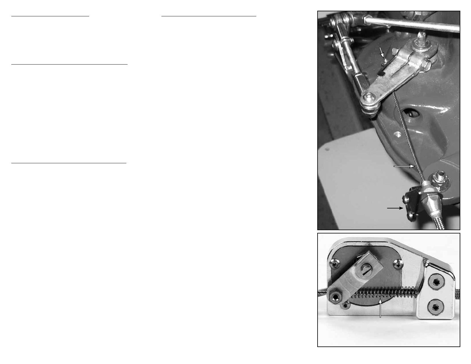
Fig. 11Fig. 11
Index Cable Index Cable
StopStop
(with Set Screw)(with Set Screw)
Inner WireInner Wire
Adjustable Cable Adjustable Cable
Mounting BracketMounting Bracket
Fig. 12Fig. 12
Spring compressed Spring compressed
approximately 1/8" at restapproximately 1/8" at rest
(Sensor removed from transmission for photo)
Mounting The Decoder Box
The decoder box must be mounted in a dry place. When mounting
this unit, keep it within reach of the wires on the LED display and the
sensor. The decoder box can be mounted with two screws or double-
sided tape. Be sure it is still accessible for connecting the wiring and for
programming later.
Wiring The Sensor and The Decoder Box
The sensor has a 10 foot long cable attached to it. This cable contains
three wires which connect to the decoder box: one red wire, one wire
that can be either green or white, and one black wire. To connect the
wires to the decoder box, use a small flat blade screwdriver to loosen
the screw terminal. Strip 3/8” of the insulation off of each of the wires.
Connect the red wire to the terminal marked RED. Connect the green or
white wire to the terminal marked GREEN. Connect the black wire to the
terminal marked BLACK. Fig. 13
NOTE: The red, green or white, and black wires on the sensor
should ONLY be connected to the terminals marked “RED”,
“GREEN”, or “BLACK” on the decoder box. DO NOT connect any
of these three wires to the “IGNITION+” or “GROUND-” terminals
on the decoder box.
Wiring a Lokar Three-Wire LED Indicator
Locate a fused (15A), switched 12V + power source that supplies power
when the ignition key is in the “ON” or “RUN” position, but does not supply
power when the key is off. (NOTE: If you are going to use the optional
Neutral Safety Relay discussed later, this wire will also need to
supply power while the key is in the “START” position.) Run a red
wire (not supplied) from that power source to the decoder box. Join the
end of that wire to the end of the red wire from the LED indicator. Insert
the joined end of those wires into the “IGNITION+” terminal on the decoder
box and tighten the terminal screw.
Connect one end of a black wire (not supplied) to a solid chassis
ground. Join the other end of that wire to the black wire from the LED
indicator. Insert the joined end of those wires into the “GROUND-”
terminal on the decoder box and tighten the terminal screw. Fig. 13
NOTE: When you are finished with this step, there will be two (2)
wires connected to the “IGNITION+” terminal on the decoder box,
and two (2) wires connected to the “GROUND-” terminal on the
decoder box.
If installing a Lokar Three-Wire LED Indicator, DO NOT connect
the remaining green or white wire from the LED Indicator to the
decoder box until you have programmed the gear positions.
Page 4


