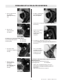
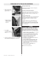
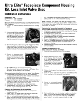
MSA FIREHAWK M7 ULTRA ELITE 10084822 Maintenance And Repair
- Type
- Maintenance And Repair
MSA FIREHAWK M7 ULTRA ELITE 10084822: Experience unparalleled respiratory protection with our revolutionary SCBA featuring a lightweight carbon fiber design, allowing for enhanced mobility and reduced user fatigue during firefighting operations.
MSA FIREHAWK M7 ULTRA ELITE 10084822: Experience unparalleled respiratory protection with our revolutionary SCBA featuring a lightweight carbon fiber design, allowing for enhanced mobility and reduced user fatigue during firefighting operations.


-
 1
1
-
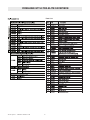 2
2
-
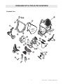 3
3
-
 4
4
-
 5
5
-
 6
6
-
 7
7
-
 8
8
-
 9
9
-
 10
10
-
 11
11
-
 12
12
-
 13
13
-
 14
14


MSA FIREHAWK M7 ULTRA ELITE 10084822 Maintenance And Repair
- Type
- Maintenance And Repair
MSA FIREHAWK M7 ULTRA ELITE 10084822: Experience unparalleled respiratory protection with our revolutionary SCBA featuring a lightweight carbon fiber design, allowing for enhanced mobility and reduced user fatigue during firefighting operations.
Ask a question and I''ll find the answer in the document
Finding information in a document is now easier with AI
Related papers

Other documents
-
Kmart 43094899 User manual
-
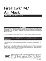 FireHawk M7 Air Mask Owner's manual
-
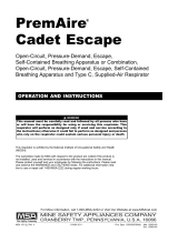 PremAire Cadet Escape Respirator Owner's manual
-
 Ultra Elite Full-Facepiece Respirators Owner's manual
-
 Ultra Elite Full-Facepiece Respirators Owner's manual
-
 Ultra Elite Full-Facepiece Respirators Owner's manual
-
 FireHawk Air Mask Upgrade Kits Owner's manual
-
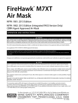 FireHawk M7XT Air Mask Owner's manual
-
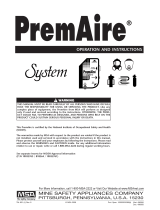 PremAire Supplied Air Respirator System Owner's manual
-
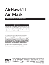 AirHawk II Air Mask Owner's manual


