Page is loading ...

421-000-438 MR Rev.1 8/03
1
Rechargeable Flashlight System™(Ni-Cad)
RX1019/RX1016
RX2019
RX3019
RX4019
RX5019
RX6019
RX7019
Mag-Lite®
Rechargeable
Flashlight
repair
manual
IMPORTANT NOTICE
This copyrighted Manual, bearing Copy Control #_______________, is the property of
Mag Instrument, Inc., and must be returned to Mag Instrument upon demand. It is for use only
by factory-certified technicians performing authorized warranty service on the Mag-Lite®
Rechargeable Flashlight and/or other Mag-Lite® Rechargeable Flashlight System™
components.
This Manual is a confidential document. It is not for sale and is not to be shown, lent or
otherwise disclosed to unauthorized personnel.
Copying of this document is not authorized. Copying would therefore constitute a violation of
the copyright laws. If additional copies are desired, they should be requested directly from
Mag Instrument, Inc.
Repairs must be performed by Mag Instrument
certified warranty service personnel

Rechargeable Flashlight
MR Rev.1 8/03 421-000-438
2
MAINTENANCE AND REPAIR INSTRUCTIONS
Rechargeable Flashlight
Warnings: Any battery may leak harmful chemicals which may damage skin, clothing,
or the inside of the flashlight TO AVOID RISK OF INJURY, DO NOT LET ANY MATERIAL
LEAKED FROM A BATTERY COME IN CONTACT WITH EYES OR SKIN. Any battery may
rupture or explode if put in a fire or otherwise exposed to excessive heat. TO AVOID
RISK OF INJURY, DO NOT EXPOSE BATTERIES TO EXCESSIVE HEAT.
INSPECTION AND MAINTENANCE
Battery Pack - Remove the battery pack from the flashlight and visually inspect for
signs of gas or chemical leakage. Indications of leakage are discoloration of the plastic
sleeve or white fuzzy material near the top (positive side button) of each cell. Another
indication would be a bulging deformation of the bottom (negative flat end) of the cell
can. If any of these signs are observed the battery pack should be removed from
service to prevent chemical damage to the inside of the flashlight.
Electrical Contacts - The bare (bright) metal surfaces between the tail cap and barrel
must be clean as well as the spring contact surface of the tail cap.
O-ring Seals and Screw Threads - To keep seals from drying out and the threads
operating smoothly, apply several drops of clean petroleum oil or jelly.

Rechargeable Flashlight MR Rev.1 8/03
3
421-000-438
RECHARGEABLE SWITCH REPLACEMENT
Rechargeable Flashlight
Tools Required:
1. Barrel Holder
2. Spanner Wrench
3. Multimeter
1. Bulb
a. Verify that you have a good LAMP and
BATTERY PACK
Probe placement
• Place red probe on one lamp pin
• Place black probe on the other lamp pin (it makes no
difference which probe goes to what pin)
• If the lamp is good you will get a (000) reading
• A (1.) is a bad lamp
2. Battery
a. Warranty – 12
months from the
four number
DATE CODE on
the battery pack
(0324). First two numbers (03) indicate
year Second two numbers (24) indicate
week of year.
b. Battery Damage. Look for:
1). Signs of gas or chemical leakage.
2). Discoloration.
3). Fuzzy material near positive button.
4). Bulging or deformation.
5). Charge for 15 minutes prior to test.
6). Test.
Battery Test
Meter Settings
Dial set at V-20 Volts
Probes: Black in
“COM” port
Red in “VΩmA” port.
Testing Procedures
(Troubleshooting)
1. Bulb 2. Battery 3. Charge Module 4. Converter 5. Circuit Board

Rechargeable Flashlight
MR Rev.1 8/03 421-000-438
4
d. Battery
Less than 6.00
volts but higher
than 4.8 volts
indicates battery
should be
charged longer
prior to test. Less
than 4.8 volts
indicates bad
battery.
c. Lead Placement
Red probe on positive button.
Black lead on flat negative end.
WARNING: do not touch bare leads
during test. Very Hot.
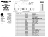
SCHEMATIC - FLASHLIGHT
PARTS LIST FOR RECHARGEABLE MAGLITE
ITEM NO. QTY PART NUMBER DESCRIPTION
1 1 205-000-001 FACE CAP
2 1 405-000-051 LENS SEAL
3 1 108-000-060 LENS (SODALIME)
4 1 108-000-020 LENS ASSEMBLY
5 105-000-002 FACE-REFLECTOR ASSEMBLY
6 1 108-000-104 REFLECTOR-HOUSING ASSEMBLY
7 1 108-000-557 SWITCH SEAL (old) or 108-000-643 (revised)
8 1 405-000-049 NYLON WASHER
9 1 205-000-014 SWITCH HOUSING CASING
10 1 405-000-016 O-RING, SWITCH HOUSING
11 2 LR00001 HALOGEN LAMP
12 1 108-000-106 SWITCH ASSEMBLY
13 1 108-000-025 O-RING, HEAD
14 1 205-000-007 HEAD
15 1 105-000-008 CHARGER MODULE
16 1 205-000-047 BARREL
17 1 108-000-032 MAIN SPRING
18 1 108-000-601 BULB PROTECTOR
19 1 108-000-207 O-RING, TAIL CAP
20 1 201-000-191 TAIL CAP
21 TAIL CAP ASSEMBLY
22 1 108-000-439 6 VOLT NI-CAD BATTERY PACK
23 1 INSULATOR SLEEVE, DIODE
24 1 105-000-010 DIODE

Rechargeable Flashlight MR Rev.1 8/03
5
421-000-438
U.S.A., STANDARD COMMERCIAL
FLASHLIGHT SPECIFICATION
FLASHLIGHT
OVERALL LENGTH: 12-19/32 in. 319.79 mm
BARREL DIAMETER: 1-9/16 in. 39.67 mm
HEAD DIAMETER: 2-5/16 in. 58.72 mm
WEIGHT WITHOUT BATTERY: 18.0 oz. 510.29 gm
WEIGHT WITH BATTERY: 32.0 oz. 907.18 gm
* BEAM CANDLEPOWER @ 10 feet / 3.0 meters 40,000 Peak Beam Candlepower
* BATTERY LIFE CONTINUOUS ON TIME: 2 hours from full charge
LAMP LIFE: 50-65 hours continuous
BATTERY VOLTAGE OUTPUT: 6 volts
EXTERIOR BODY COMPONENTS: Machined high strength aluminum alloy
EXTERIOR BODY FINISH: Anodized commercial type III hard, inside and outside
LENS: Ground and tempered glass
BATTERY: 6 volt 2.2 amp hr. to 2.5 amp hr. Five (5) 1/2 D size NI-CAD (Nickel-Cadmium) pack
REFLECTOR: Highly polished metal
SWITCH: Recessed push button, sealed, self cleaning, On-Off
and momentary on
LAMP: 6 volt 1.4 amp 8.4 watts High pressure Halogen, G-4 Bi-pin base
SPARE LAMP: Spare lamp located in tail cap
O-RING SEALED: Sealed throughout for improved water resistance
FOCUS: Adjustable beam, spot to flood (1/4) head turn
SERIAL NUMBERED: Stamped on barrel
CHARGE CONTACTS: 360 degree contacts. Flashlight charges in any position
* Candlepower and battery on time may vary between lamps and battery packs.
Note: The battery discharge rate when not in use is approximately 1% per day.
CHARGER
• Accepts 12-14 volts maximum DC input (Not for use with 24 volt circuits)
• Battery charge time to full charge 14-16 hours
• Charge rate: 220 mA constant current
• Reverse voltage protected output (battery in backwards)
• Red LED charge indicator
• Mounts in any position
• Two (2) detachable mounting brackets (i.e. for mounting in two locations)
CONVERTOR U.S.A.
• INPUT: 117 volts AC, 60 Hz
• OUTPUT: 14 volts DC, .22 Amps
CONVERTOR EUROPEAN (Not for all countries)
• INPUT: 230 volts AC, 50 Hz
• OUTPUT: 14 volts DC, .22 Amps.
Note: All information contained in this specification is for reference purposes only. Mag Instrument, Inc. reserves
the right to change any information without notice.

Rechargeable Flashlight
MR Rev.1 8/03 421-000-438
6
STEP 1
Remove TAIL CAP ASSEMBLY(21)
(counterclockwise) and BATTERY PACK (22).
STEP 2
Remove the FACE CAP ASSEMBLY (5)
(counterclockwise).
STEP 4
Remove the SWITCH SEAL (7) by grasping
the seal with your thumb and index finger,
buckle and pull to extract.
STEP 3
Remove the REFLECTOR (6) from the FACE
CAP (1). The REFLECTOR (6) unscrews
(counterclockwise) . To replace it push hard
on the REFLECTOR (6) to get it past the
threads.*Note: Removal of reflector should
not be necessary unless the LENS (3) or
REFLECTOR (6) is damaged.

Rechargeable Flashlight MR Rev.1 8/03
7
421-000-438
STEP 8
Unscrew BARREL (16) counterclockwise.
STEP 7
Push the plunger into the barrel switch hole.
STEP 5
Remove the LAMP (11) by pulling straight
up until the pins are clear of the receptacle.
*Note: It is easier to change the LAMP (11) if
you push the HEAD (14) down over the
SWITCH HOUSING (9).
CAUTION: This bulb is pressurized and CAN SHATTER OR EXPLODE,
causing PERSONAL INJURY. Wear protective eyeglasses and clothing
when handling; never exceed rated voltage (6.0 VDC); never scratch
bulb’s glass envelope; never splash bulb with liquids. Bulb BURNS
VERY HOT and CAN CAUSE BURN INJURY OR HEAT OR FIRE DAMAGE.
Remove battery pack and let bulb cool before handling; avoid operating
near materials that are flammable or prone to heat or drying damage.
Dispose of lamp with care.
STEP 6
Lift up the plunger of the barrel holder and
insert the flashlight, BARREL (16), first into
the front of the barrel tool holder, lining the
switch hole up with the plunger.

Rechargeable Flashlight
MR Rev.1 8/03 421-000-438
8
STEP 10
Unscrew (counterclockwise) the CHARGER
MODULE (15) 2-3 turns.
STEP 12
Unscrew and remove the CHARGER
MODULE (15) from the SWITCH HOUSING (9)
STEP 11
Lift up the plunger and remove the HEAD
(14), SWITCH HOUSING (9), and CHARGER
MODULE (15) from the TOOL HOLDER.
STEP 9
Insert the SPANNER WRENCH into the back
of the BARREL HOLDER TOOL and match
the pins of the holder with the holes in the
CHARGER MODULE (15).

Rechargeable Flashlight MR Rev.1 8/03
9
421-000-438
B. LEAD PLACEMENT
1. The black lead is on the spring.
2. The red lead is on the outer
charging ring.
PROBLEM
Occasionally the CHARGER MODULE
(15) will stay in the BARREL (16) when it
is unscrewed. If this happens do the
following:
A. CHARGE MODULE METER SETTINGS
Meter reading is .005 – .764 mA. A bad
module will register .000 or 1 mA.
A. METER SETTINGS
Dial should be at 2k Ωohms.
1. The black probe in the“COM” Port
2. The red probe in the “V_mA” port.
3. The meter should be reading “1.”
CHARGER MODULE TEST

Rechargeable Flashlight
MR Rev.1 8/03 421-000-438
10
After you have removed the silver ring and
insulator ring you will see the flat surface
where the rings had been.
Try to unscrew the MODULE (15) without
damaging the flat surface or the threads. Use
a pair of pliers and a rubber band, grip the
flat surface as gently as possible and
unscrew the MODULE (15)
(counterclockwise).
PROBLEM (cont.)
Separate the silver ring and black insulator
from the MODULE (15) by inserting your
finger nail or a knife blade between the ring
and the second insulator. The ring is held in
place by the spring loaded diode shown
next to the top thumb.
The diode shown in the picture is attached to a
spring and insulated by a plastic sleeve. In this
picture the sleeve is not shown and is still in
the diode hole of the MODULE (15).
Occasionally the diode might fall out when you
are unscrewing the MODULE (15), note how it
goes back into the hole and MAKE SURE THE
PLASTIC SLEEVE IS IN PLACE. A severe SHORT
will occur if the sleeve is missing.

Rechargeable Flashlight MR Rev.1 8/03
11
421-000-438
Before replacing the plastic insulator note
the lip on one side of the insulator ring.
The lip on the insulator ring goes against the
silver ring so that the flat side will be facing
out. It will snap into place.
When replacing the ring onto the MODULE
(15) place the ring over the diode pin, push
down and snap the ring in place.
STEP 13
Push the HEAD (14) down and over the
O-RING (10) and remove it from the SWITCH
HOUSING (9).

Rechargeable Flashlight
MR Rev.1 8/03 421-000-438
12
FIGURE 1
REPLACEMENT SWITCH
The Replacement SWITCH (12) should come
with the internal mechanism partially out of
the housing, the push button will be down
and held in place by the housing so that the
SWITCH (12) can easily fit into the SWITCH
HOUSING (9).
STEP 15
REPLACE SWITCH
Insert the SWITCH ASSEMBLY (12) into
the rear of the SWITCH HOUSING (9).
FIGURE 2
If the push button is up, use a ball point pen
or pencil and: Push the button down and at
the same time push the entire mechanism
out the back of the housing.
When you remove the pen the button
should be locked under the housing as
shown in figure 1.
STEP 14
Depress the switch button on the SWITCH
(12) and at the same time push the SWITCH
ASSEMBLY (12) out the back of the SWITCH
HOUSING (9).

Rechargeable Flashlight MR Rev.1 8/03
13
421-000-438
STEP 17
Push hard on the black plastic portion of the
SWITCH (12) and it should click into place
with the push button centered in the switch
hole of the HOUSING (9).
STEP 18
Slide the HEAD (14) over the SWITCH
HOUSING (9), make sure it slides over the
O-RING (10).
STEP 16
Make sure the SWITCH (12) is seated evenly
in the SWITCH HOUSING (9). Do not press on
the black plastic portion of the SWITCH (12)
until you are certain it is seated properly.
STEP 19
Screw the CHARGER MODULE (15)
(clockwise) into the SWITCH HOUSING
(9), finger tight.

Rechargeable Flashlight
MR Rev.1 8/03 421-000-438
14
STEP 21
Push the flashlight into the tool holder until
the HEAD (14) stops at the holder. Push the
plunger down into the switch hole.
STEP 22
Insert the spanner wrench into the tool
holder and rotate until the pins in the holder
fall into the holes in the CHARGER MODULE
(9). Tighten the CHARGER MODULE (9)
(clockwise) as tight as possible.
STEP 20
Pull the plunger on the tool holder up and
place the flashlight, CHARGER MODULE (9)
end first into the front of the tool holder.
Make sure the switch hole is lined up with
the plunger.
STEP 23
Insert the silver ringed portion of the
BARREL (16) into the rear of the tool
holder and screw it into the CHARGER
MODULE ( 9) (clockwise), tighten by
hand as tight as possible.

Rechargeable Flashlight MR Rev.1 8/03
15
421-000-438
STEP 25
Push the head down and replace the LAMP
(11) by lining up the pins of the LAMP (11)
with the two holes in the switch receptacle
and apply a straight downward pressure.
STEP 26
Replace the SWITCH SEAL (7) by bowing it
slightly with the thumb and index finger to
get it started into the hole in the BARREL
(16). Push all outside edges of the SEAL (7)
into the BARREL (16) hole.
STEP 24
Remove the flashlight from the barrel
holder tool.
STEP 27
Replace the BATTERY PACK (22) be sure
you insert the positive (button end) into
the light first. replace the TAIL CAP
ASSEMBLY (21), make sure you put
lubrication on all o-rings and threads.
CAUTION: This bulb is pressurized and CAN SHATTER OR EXPLODE,
causing PERSONAL INJURY. Wear protective eyeglasses and clothing
when handling; never exceed rated voltage (6.0 VDC); never scratch
bulb’s glass envelope; never splash bulb with liquids. Bulb BURNS
VERY HOT and CAN CAUSE BURN INJURY OR HEAT OR FIRE DAMAGE.
Remove battery pack and let bulb cool before handling; avoid operating
near materials that are flammable or prone to heat or drying damage.
Dispose of lamp with care.

Rechargeable Flashlight
MR Rev.1 8/03 421-000-438
16
STEP 29
Hold the REFLECTOR (6) down with your
thumb as you hold the HEAD (14) with your
fingers as shown. This allows you to hold
the REFLECTOR (6) down and turn the HEAD
(14) for adjustment.
STEP 30
Using a pencil eraser and with the light OFF,
center the LAMP) (11) in the REFLECTOR (6)
hole. DO NOT TOUCH THE REFLECTORS
SURFACE or TRY TO CLEAN IT WITH
ANYTHING.
STEP 28
BULB ALIGNMENT
Before replacing the FACE CAP ASSEMBLY
(5) check for proper bulb alignment.
Using a test REFLECTOR (6) place it into the
head as shown.
STEP 31
While still holding the REFLECTOR (6) in the
HEAD (14) turn on the light, put it in spot
mode and observe the spot pattern. If the
LAMP (11) is aligned properly you should see
a dark “V” shape on each side of the spot.
(This is with all LAMPS after January 2002).


Rechargeable Flashlight MR Rev.1 8/03
19
421-000-438
ITEM NO# QTY PART NUMBER DESCRIPTION
1 1 109-000-485 CHARGER CRADLE ASSEMBLY
2 1 405-000-025 SPRING CLAMP
3 1 105-000-021 CIRCUIT BOARD ASSEMBLY
4 1 405-000-028 SCREW, CIRCUIT BOARD #6X5/16
5 1 405-000-103 FIBER WASHER
6 4 405-000-047 SCREW, BASE PLATE #6X3/4
7 1 405-000-096 BASE PLATE
8 1 108-000-440 CHARGER BRACKET
1 108-000-437 110 VOLT AC CONVERTER
1 108-000-438 12 VOLT DC CORD W/CIG. LIGHTER PLUG
1 405-000-089 12 VOLT DC STRAIGHT WIRE

Rechargeable Flashlight
MR Rev.1 8/03 421-000-438
20
CHARGER TESTS
Tests should be performed to determine the problem area prior to
replacing the circuit board.
CONVERTER TEST
METER READING
1. Dial is at V-20 volts.
2. Black probe is in the “COM” port.
3. Red probe is in the “VΩmA” port.
CONVERTER
METER READING
1. Between 13.00 & 22.00 volts.
CIRCUIT BOARD TEST
METER SETTING
1. Set the dial at “A- 10A” Amps.
2. Black probe in “COM” port.
3. Red probe in “10ADC” port.
CONVERTER
LEAD REPLACEMENT
1. Place the leads, Red & Black into the pin
receptacles of the converter plug, (it does
not make a difference which lead goes into
which hole).
/