Page is loading ...

Rev. A
June 2023 TTKK 5577224499--1199--IIMM--EENN
TriPac® Envidia™ 2
Auxiliary Heating and Cooling Temperature Management
System
Installation Manual

©2023 Trane Technologies TK 57249-19-IM-EN
Introduction
This manual was written only to assist with the installation of the TThheerrmmoo KKiinngg TTrriiPPaacc EEnnvviiddiiaa 22 AAuuxxiilliiaarryy HHeeaattiinngg
aanndd CCoooolliinngg SSyysstteemmss onto a typical Class 8 semi truck with sleeper. The TThheerrmmoo KKiinngg TTrriiPPaacc IInnssttaallllaattiioonn SSttaannddaarrddss
GGuuiiddee (TK 56498) provides more detailed information that must be followed to safely and properly complete the entire
installation.
Before beginning the installation, the installer should confirm with the customer the location for each of the APU’s
components by using the AAPPUU IInnssttaallllaattiioonn QQuueessttiioonnnnaaiirree. The customer should also be made aware that
modifications to existing equipment might be necessary to complete the installation.
MMooddiiffiiccaattiioonnss mmaayy iinncclluuddee::
• Truck’s engine must be fitted with an upgraded alternator of 270 amps or more and with upgraded alternator wiring
of OEM approved design.
• APU condenser may be directly mounted to the outside of the sleeper.
• APU evaporator, power inverter and/or converter may be installed in existing storage spaces under the bunk or in
the toolbox areas.
• APU heating and A/C duct work may to be routed with vents installed in existing closets or storage compartments.
• OEM components on the chassis may need to be relocated to accommodate the installation of the APU battery box.
• OEM fuel tank may need to be changed to a smaller size to accommodate the installation of the APU battery box.
• For base level performance - truck battery box must have four 12Vdc batteries connected to provide 12Vdc output.
• For optimum level performance - truck batteries may be upgraded to Thermo King NXT 1150 CCA absorbed glass
mat (AGM) batteries.
DDuuee ttoo iittss ccoommpplleexxiittyy,, yyoouu sshhoouulldd nnoott aatttteemmpptt tthhiiss iinnssttaallllaattiioonn uunnlleessss yyoouu::
• Are an experienced mechanic.
• Can safely lift 34 kilos (75 lbs.)
• Are EPA Section 609 certified and trained in the repair and maintenance of mobile air conditioning systems (in the
United States).
• Have a basic understanding of electricity and electrical wiring.
• Have the necessary tools and equipment to complete the installation.
• Follow the safety precautions outlined in the Thermo King TriPac Installation Standards Guide (TK 56498).
This manual is published for informational purposes only. Thermo King makes no representations warranties express
or implied, with respect to the information recommendations and descriptions contained herein. Information provided
should not be regarded as all-inclusive or covering all contingencies. If further information is required, Thermo King
Corporation Service Department should be consulted. Thermo King’s warranty shall not apply to any equipment which
has been “so installed, maintained, repaired or altered as, in the manufacturer’s judgment, to affect its integrity.”
Manufacturer shall have no liability to any person or entity for any personal injury, property damage or any other direct,
indirect, special, or consequential damages whatsoever, arising out of the use of this manual or any information,
recommendations or descriptions contained herein.
Revision History
Revision A (6/23) Released new manual.

TK 57249-19-IM-EN 3
Customer Satisfaction Survey
Let your voice be heard!
Your feedback will help improve our manuals. The survey is accessible through any internet-connected device with a
web browser.
Scan the Quick Response (QR) code or click Technical Publications TK Americas Feedback to complete the survey.
IInnttrroodduuccttiioonn

4TK 57249-19-IM-EN
TTiippss FFoorr aa SSuucccceessssffuull IInnssttaallllaattiioonn ............................................................................................................................ 77
Before Beginning the Installation Recommendations . . . . . . . . . . . . . . . . . . . . . . . . . . . . . . . . . . . . . . . . . . . . . . 7
Truck’s Alternator Requirements . . . . . . . . . . . . . . . . . . . . . . . . . . . . . . . . . . . . . . . . . . . . . . . . . . . . . . . . . . . . . . . . . 7
Truck’s Battery Recommendations . . . . . . . . . . . . . . . . . . . . . . . . . . . . . . . . . . . . . . . . . . . . . . . . . . . . . . . . . . . . . . . 7
APU Battery Requirements . . . . . . . . . . . . . . . . . . . . . . . . . . . . . . . . . . . . . . . . . . . . . . . . . . . . . . . . . . . . . . . . . . . . . . 7
Battery Box Installation Requirements . . . . . . . . . . . . . . . . . . . . . . . . . . . . . . . . . . . . . . . . . . . . . . . . . . . . . . . . . . . . 9
A/C Condenser Installation Requirements . . . . . . . . . . . . . . . . . . . . . . . . . . . . . . . . . . . . . . . . . . . . . . . . . . . . . . . . . 9
A/C Evaporator / Control Box Installation Requirements . . . . . . . . . . . . . . . . . . . . . . . . . . . . . . . . . . . . . . . . . . . . 9
A/C Hose Connections and Routing Requirements . . . . . . . . . . . . . . . . . . . . . . . . . . . . . . . . . . . . . . . . . . . . . . . . 10
Electrical Wiring and HMI Controller Installation Requirements . . . . . . . . . . . . . . . . . . . . . . . . . . . . . . . . . . . . 11
D2 / D4 Heater Installation Requirements (Units with Heat Option) . . . . . . . . . . . . . . . . . . . . . . . . . . . . . . . . . 11
Auxiliary Power Accessories Requirements . . . . . . . . . . . . . . . . . . . . . . . . . . . . . . . . . . . . . . . . . . . . . . . . . . . . . . 12
RReeqquuiirreedd TToooollss aanndd AAddddiittiioonnaall SSuupppplliieess............................................................................................................ 1133
TTrriiPPaacc EEnnvviiddiiaa aanndd EEnnvviiddiiaa 22 CCoommppoonneenntt DDiimmeennssiioonnss .............................................................................. 1155
Battery Box Dimensions . . . . . . . . . . . . . . . . . . . . . . . . . . . . . . . . . . . . . . . . . . . . . . . . . . . . . . . . . . . . . . . . . . . . . . . . 15
Condenser Dimensions. . . . . . . . . . . . . . . . . . . . . . . . . . . . . . . . . . . . . . . . . . . . . . . . . . . . . . . . . . . . . . . . . . . . . . . . . 17
Evaporator/Control Box Dimensions. . . . . . . . . . . . . . . . . . . . . . . . . . . . . . . . . . . . . . . . . . . . . . . . . . . . . . . . . . . . . 18
HMI Controller Dimensions . . . . . . . . . . . . . . . . . . . . . . . . . . . . . . . . . . . . . . . . . . . . . . . . . . . . . . . . . . . . . . . . . . . . . 19
Standard Heater Dimensions . . . . . . . . . . . . . . . . . . . . . . . . . . . . . . . . . . . . . . . . . . . . . . . . . . . . . . . . . . . . . . . . . . . 20
High Output Heater Dimensions. . . . . . . . . . . . . . . . . . . . . . . . . . . . . . . . . . . . . . . . . . . . . . . . . . . . . . . . . . . . . . . . . 21
AC/DC Shore Power Converter Dimensions . . . . . . . . . . . . . . . . . . . . . . . . . . . . . . . . . . . . . . . . . . . . . . . . . . . . . . 22
1000 Watt Power Inverter Dimensions . . . . . . . . . . . . . . . . . . . . . . . . . . . . . . . . . . . . . . . . . . . . . . . . . . . . . . . . . . . 23
TTyyppiiccaall CCoommppoonneenntt LLooccaattiioonnss .......................... .............................. .............. .................... ........................ ................ 2244
BBaatttteerryy BBooxx IInnssttaallllaattiioonn ................................................................................................................................................ 2266
Standard Installation Method – Mounting Claws. . . . . . . . . . . . . . . . . . . . . . . . . . . . . . . . . . . . . . . . . . . . . . . . . . 26
Optional Installation Method – Direct Mount . . . . . . . . . . . . . . . . . . . . . . . . . . . . . . . . . . . . . . . . . . . . . . . . . . . . . 28
RReecceeiivveerr DDrriieerr IInnssttaallllaattiioonn .................. .............................. ................ ............................ ................ ............................ .. 3300
A/C Condenser Installation. . . . . . . . . . . . . . . . . . . . . . . . . . . . . . . . . . . . . . . . . . . . . . . . . . . . . . . . . . . . . . . . . . . . . . 32
AA//CC EEvvaappoorraattoorr // CCoonnttrrooll BBooxx IInnssttaallllaattiioonn .............................................. .............. .............................. ................ 3333
AA//CC HHoossee IInnssttaallllaattiioonn.............................. ................ .............................. .............. .............................. .............. ................ 3366
AA//CC SSyysstteemm EEvvaaccuuaattiioonn aanndd LLeeaakk CChheecckk PPrroocceedduurreess .................................................................................. 3377
DD22//DD44 HHeeaatteerr IInnssttaallllaattiioonn ((HHeeaatt OOppttiioonn))...................................... .......................... ................ .............................. 3388
Heater Location. . . . . . . . . . . . . . . . . . . . . . . . . . . . . . . . . . . . . . . . . . . . . . . . . . . . . . . . . . . . . . . . . . . . . . . . . . . . . . . . 38
Heater Subassembly and Installation . . . . . . . . . . . . . . . . . . . . . . . . . . . . . . . . . . . . . . . . . . . . . . . . . . . . . . . . . . . . 39
Table of Contents

TK 57249-19-IM-EN 5
Exhaust and Combustion Air Intake Installation . . . . . . . . . . . . . . . . . . . . . . . . . . . . . . . . . . . . . . . . . . . . . . . . . . 40
Return and Discharge Ducts and Vents Installation. . . . . . . . . . . . . . . . . . . . . . . . . . . . . . . . . . . . . . . . . . . . . . . . 41
AA//CC DDuucctt IInnssttaallllaattiioonn .. .. ........ .... .............. .... ............ .... .......... ............ .... .............. .... .......... .... ............ .......... .... ................ 4422
Discharge Air Outlet Options. . . . . . . . . . . . . . . . . . . . . . . . . . . . . . . . . . . . . . . . . . . . . . . . . . . . . . . . . . . . . . . . . . . . 42
Discharge Air Duct Installation . . . . . . . . . . . . . . . . . . . . . . . . . . . . . . . . . . . . . . . . . . . . . . . . . . . . . . . . . . . . . . . . . . 43
Discharge Air Vent Installation . . . . . . . . . . . . . . . . . . . . . . . . . . . . . . . . . . . . . . . . . . . . . . . . . . . . . . . . . . . . . . . . . . 43
Backflow Damper Installation . . . . . . . . . . . . . . . . . . . . . . . . . . . . . . . . . . . . . . . . . . . . . . . . . . . . . . . . . . . . . . . . . . . 45
BBaatttteerryy BBooxx HHaarrnneessss IInnssttaallllaattiioonn ............................................................................................................................ 4466
CCoonnddeennsseerr FFaann aanndd SSeennssoorr HHaarrnneessss IInnssttaallllaattiioonn .......................................................................................... 5500
IIggnniittiioonn SSwwiittcchh aanndd HHaarrnneessss IInnssttaallllaattiioonn............................................................................................................ 5511
HHMMII IInnssttaallllaattiioonn .. .. .... .... ...... ........ .............. .... ............ .... .......... ........ ........ .............. .... .......... .... ............ ...... ........ ................ 5522
UUSSBB SSeerrvviiccee CCoommmmuunniiccaattiioonn CCaabbllee IInnssttaallllaattiioonn............................................................................................ 5533
DD22//DD44 HHeeaatteerr HHaarrnneessss IInnssttaallllaattiioonn ((HHeeaatt OOppttiioonn)) .............. .... ............ .... .......... .... ............ .............. .... ............ 5544
HHeeaatteerr FFuueell PPiicckkuupp TTuubbee IInnssttaallllaattiioonn ((HHeeaatt OOppttiioonn)) .. .. ...... .... .......... .... .......... ............ .... .............. .... ............ 5555
Direct Tank Installation – with OEM Fuel Tank Fittings. . . . . . . . . . . . . . . . . . . . . . . . . . . . . . . . . . . . . . . . . . . . . 55
Alternative Installation – Drilling Hole in Fuel Tank. . . . . . . . . . . . . . . . . . . . . . . . . . . . . . . . . . . . . . . . . . . . . . . . 57
FFuueell PPuummpp aanndd FFuueell LLiinnee IInnssttaallllaattiioonn ((HHeeaatt OOppttiioonn)) .. .. ...... ............ .... ............ .... ............ .... .......... .............. .. 5599
Tank Mounted Fuel Pump . . . . . . . . . . . . . . . . . . . . . . . . . . . . . . . . . . . . . . . . . . . . . . . . . . . . . . . . . . . . . . . . . . . . . . 59
Remote Mounted Fuel Pump with L-Bracket. . . . . . . . . . . . . . . . . . . . . . . . . . . . . . . . . . . . . . . . . . . . . . . . . . . . . . 60
HHeeaatteerr FFuueell PPuummpp CCoonnnneeccttiioonnss ((HHeeaatt OOppttiioonn)) .. .... ...... .......... .............. .... .......... .... ............ ...... ........ ................ 6611
AAuuxxiilliiaarryy AACC PPoowweerr AAcccceessssoorriieess ((OOppttiioonn)).. .... .... ...... .......... ...... .............. .... .......... .... ............ .......... .... ................ 6622
DC/AC Power Inverter Only . . . . . . . . . . . . . . . . . . . . . . . . . . . . . . . . . . . . . . . . . . . . . . . . . . . . . . . . . . . . . . . . . . . . . 62
AC/DC Shore Power Converter Only . . . . . . . . . . . . . . . . . . . . . . . . . . . . . . . . . . . . . . . . . . . . . . . . . . . . . . . . . . . . . 63
Dual System – DC/AC Power Inverter and AC/DC Shore Power Converter . . . . . . . . . . . . . . . . . . . . . . . . . . . 64
BBaatttteerryy CCaabbllee IInnssttaallllaattiioonn ............................................................................................................................................ 6655
PPrriimmiinngg tthhee HHeeaatteerr FFuueell PPuummpp ((HHeeaatt OOppttiioonn)) .................................................................................................. 6677
HHeeaatteerr SSttaarrtt--UUpp PPrroocceedduurreess ((HHeeaatt OOppttiioonn)) .. .. .... .... ................ .... .......... .... .......... ...... .......... .............. .... ............ 6688
Diagnostic Tool Overview . . . . . . . . . . . . . . . . . . . . . . . . . . . . . . . . . . . . . . . . . . . . . . . . . . . . . . . . . . . . . . . . . . . . . . 68
Perform the Start-Up Procedure. . . . . . . . . . . . . . . . . . . . . . . . . . . . . . . . . . . . . . . . . . . . . . . . . . . . . . . . . . . . . . . . . 68
Heater Start-Up . . . . . . . . . . . . . . . . . . . . . . . . . . . . . . . . . . . . . . . . . . . . . . . . . . . . . . . . . . . . . . . . . . . . . . . . . . . . 70
Clearing Faults . . . . . . . . . . . . . . . . . . . . . . . . . . . . . . . . . . . . . . . . . . . . . . . . . . . . . . . . . . . . . . . . . . . . . . . . . . . . . . . . 70
QuitStart-Up.................................................................................. 71
Unable to Perform the Diagnosis . . . . . . . . . . . . . . . . . . . . . . . . . . . . . . . . . . . . . . . . . . . . . . . . . . . . . . . . . . . . . . . . 71
TTaabbllee ooff CCoonntteennttss

6TK 57249-19-IM-EN
AA//CC SSyysstteemm CChhaarrggiinngg PPrroocceedduurreess .. .. .... .......... .......... .... ................ .... .......... .... .......... ............ .... .............. .... ............ 7722
OOppeerraattiioonn CChheecckkoouutt PPrroocceedduurreess...................... .............. .... ............ .... .......... ............ .... .............. .... .......... .... ............ 7733
Step 1 – Basic Operation Checkout Procedures . . . . . . . . . . . . . . . . . . . . . . . . . . . . . . . . . . . . . . . . . . . . . . . . . . . 73
Step 2 - Detailed Operation Checkout Procedures . . . . . . . . . . . . . . . . . . . . . . . . . . . . . . . . . . . . . . . . . . . . . . . . . 74
Unit Setup Procedures . . . . . . . . . . . . . . . . . . . . . . . . . . . . . . . . . . . . . . . . . . . . . . . . . . . . . . . . . . . . . . . . . . . . . . . . . 74
Envidia 2 HVAC Function Check Procedures . . . . . . . . . . . . . . . . . . . . . . . . . . . . . . . . . . . . . . . . . . . . . . . . . . . . . . 75
Air Conditioning Test . . . . . . . . . . . . . . . . . . . . . . . . . . . . . . . . . . . . . . . . . . . . . . . . . . . . . . . . . . . . . . . . . . . . . . . 75
Heat System Check . . . . . . . . . . . . . . . . . . . . . . . . . . . . . . . . . . . . . . . . . . . . . . . . . . . . . . . . . . . . . . . . . . . . . . . . . 75
Fan Only Check . . . . . . . . . . . . . . . . . . . . . . . . . . . . . . . . . . . . . . . . . . . . . . . . . . . . . . . . . . . . . . . . . . . . . . . . . . . . 75
Alarms........................................................................................ 76
EEnnvviiddiiaa 22 BBaatttteerryy CChheecckk PPrroocceedduurreess........................................................... 76
Battery Condition . . . . . . . . . . . . . . . . . . . . . . . . . . . . . . . . . . . . . . . . . . . . . . . . . . . . . . . . . . . . . . . . . . . . . . . . . . 76
Battery Discharge . . . . . . . . . . . . . . . . . . . . . . . . . . . . . . . . . . . . . . . . . . . . . . . . . . . . . . . . . . . . . . . . . . . . . . . . . . 76
Battery Charge . . . . . . . . . . . . . . . . . . . . . . . . . . . . . . . . . . . . . . . . . . . . . . . . . . . . . . . . . . . . . . . . . . . . . . . . . . . . . 76
Exiting Envidia Service Tool . . . . . . . . . . . . . . . . . . . . . . . . . . . . . . . . . . . . . . . . . . . . . . . . . . . . . . . . . . . . . . . . . . . . 77
TTaabbllee ooff CCoonntteennttss

TK 57249-19-IM-EN 7
Tips For a Successful Installation
Before Beginning the Installation Recommendations
IImmppoorrttaanntt:: Proper installation of each component onto the vehicle is critical! Refer to the Thermo King TriPac
Installation Standards Guide (TK 56498) before beginning the installation. Adhering to the installation
standards will help assure the components are installed correctly and the system operates as designed. It is
the responsibility of the installer to follow these standards.
• Review component location diagram and discuss with the customer where each component will be installed on the
truck.
• Verify tools and special equipment required for the installation are available and in good working condition.
• Open all installation kits and inspect the contents before beginning installation.
• It is recommended that one person performs the installation of all the components oouuttssiiddee the sleeper while a
second person installs all the components iinnssiiddee the sleeper. This will help minimize any damage to the sleeper’s
interior from grease, dirt, etc.
Truck’s Alternator Requirements
• The truck’s engine must be fitted with an upgraded alternator of 270 amps or more and with upgraded alternator
wiring of OEM approved design.
Truck’s Battery Recommendations
• It is important not to allow the truck’s batteries to become discharged during the APU installation process. A battery
charger should be connected to the batteries while the installation is in process or shut the truck’s battery power
supply completely off using the OEM main battery disconnect switch if available.
• An alternative method is to shut the truck’s battery power completely off using the OEM main battery disconnect
switch if available.
• For TriPac Envidia 2 bbaassee lleevveell ppeerrffoorrmmaannccee::The truck’s battery box must have four 12Vdc batteries connected in
parallel to provide 12Vdc output.
• For TriPac Envidia 2 ooppttiimmuumm lleevveell ppeerrffoorrmmaannccee::Thermo King recommends the truck’s batteries be upgraded to
Thermo King NXT 1150 CCA absorbed glass mat (AGM) batteries.
APU Battery Requirements
TriPac Envidia 2 units are shipped with Thermo King NXT AGM batteries fully charged and ready to use. Batteries that
are kept in stock should not require charging for 2 years if kept below 77 F (25 C). Batteries should be charged when the
open circuit voltage (OCV) falls below 12.50 volts.
To charge the NXT AGM battery, use the following guidelines:
1. Verify the output voltage of your battery charger is capable of maintaining 14.1 to 14.7 charging voltage. The
recommended charging voltage range for the NXT AGM battery is 14.1 to 14.7 volts. Voltages are to be measured at
the battery terminals with the battery connected to the charger.
IImmppoorrttaanntt:: Never exceed 15 volts when charging the NXT AGM battery. Exceeding 15 volts will cause pressure
relief valves to open and out-gas hydrogen and oxygen from inside the battery. This will shorten the life
of the battery and could lead to premature battery failure.
2. Battery chargers with the battery type output setting should be set to AGM type battery.
DDOO NNOOTT set the output type to gel cell or maintenance free settings.
3. Determine if your battery charger is an automatic or manual charger. Manual battery chargers must be closely
monitored during the charge period and for this reason an automatic battery charger is preferred over a manual
charger.
a. Automatic battery chargers either charge up to a preset voltage and shut off, or charge to a present voltage and
then switch to a trickle charge mode. Either one of these battery chargers is acceptable: however, the automatic
charger that shuts off may not fully charge the battery.
b. Manual battery chargers will have manual controls for setting the charge amperage rate. The charge amperage
rate will remain the same until the battery charger is manually shut off.

8TK 57249-19-IM-EN
IImmppoorrttaanntt:: When using a manual battery charger, set the charger to charge at 10 or 20 amps and limit the
charging time based on the batteries state of charge (SOC). Use the chart below as a general guide
to determine the amount of time necessary to charge the battery. DDOO NNOOTT oovveerrcchhaarrggee tthhee
bbaatttteerriieess!! See warning below.
Determining Maximum Charge Time Using a Manual Charger
Voltmeter Reading State of Charge Time @ 10 Amps Time @ 20 Amps
12.84 Volts 100% 0 Hours 0 Hours
12.50 Volts 75% 2 Hours 1 Hour
12.20 Volts 50% 4 Hours 2 Hours
11.88 Volts 25% 6 Hours 3 Hours
WWAARRNNIINNGG
RRiisskk ooff IInnjjuurryy!!
OOvveerrcchhaarrggiinngg aa bbaatttteerryy ccaann ccaauussee ddaammaaggee ttoo tthhee bbaatttteerryy aanndd ppoossssiibbllyy ccaauussee aa ffiirree oorr eexxpplloossiioonn.. FFoollllooww tthhee
bbaatttteerryy cchhaarrggeerr’’ss rreeccoommmmeennddaattiioonnss ffoorr mmoonniittoorriinngg bbaatttteerriieess wwhhiillee cchhaarrggiinngg.. BBaatttteerriieess sshhoouulldd bbee
mmoonniittoorreedd wwhhiillee cchhaarrggiinngg ffoorr ssiiggnnss ooff iinntteerrnnaall pprroobblleemmss.. SSiiggnnss ooff iinntteerrnnaall pprroobblleemmss iinncclluuddee bbuullggiinngg ccaasseess,,
eexxttrreemmee ggaassssiinngg,, ppuunnggeenntt ssmmeellll,, aanndd eexxttrreemmee hheeaatt.. IIff yyoouu nnoottiiccee aannyy ooff tthheessee ssiiggnnss ttuurrnn tthhee cchhaarrggeerr ooffff aanndd
aallllooww tthhee bbaatttteerryy ttoo ssttaabbiilliizzee bbeeffoorree hhaannddlliinngg oorr tteessttiinngg..
CClleeaanniinngg aa BBaatttteerryy
Use a damp cloth to clean the top of the battery to eliminate conductive paths created by dirt and dried or wet
electrolyte, and to prevent corrosion. Use a battery terminal-cleaning tool that has nonconducting (plastic or rubber)
cover to clean the battery terminals when corrosion is present. Replace any battery cables (or cable terminals) that
are frayed, corroded, swelled, or damaged to the extent that they cannot be cleaned.
BBaatttteerryy HHoolldd DDoowwnn HHaarrddwwaarree
Batteries are subjected to extreme shock loads and vibration. It is very important to make sure each battery is
secured by the proper mounting hardware. Failure to secure each battery correctly can result in premature battery
failure. Using a torque wrench, torque the hold down nuts in two step increments:
• STEP 1 - Torque each hold down nut to 60 in-lbs. (6.8 Nm)
• STEP 2 - Torque each hold down nut to 120 to 144 in-lbs. (13.5 to 16.3 Nm)
BBaatttteerryy CCaabbllee MMoouunnttiinngg
• On threaded stud type batteries, use only stainless steel nuts to fasten the cable to the battery. Torque the nut to
150 to 200 in-lbs. (17 to 22.5 Nm).
• On SAE post type batteries, use only stainless steel battery clamp bolts. Torque the nut to 60 in-lbs. (7 Nm).
TTiippss FFoorr aa SSuucccceessssffuull IInnssttaallllaattiioonn

TK 57249-19-IM-EN 9
Battery Box Installation Requirements
IImmppoorrttaanntt:: See “Battery Box Installation Standards” in Section 6 of the Thermo King TriPac Installation Standards
Guide (TK 56498). THESE STANDARDS MUST BE FOLLOWED!
• The battery box is designed to be mounted oonnllyy to the existing truck frame rails. NNOO OOTTHHEERR MMOOUUNNTTIINNGG
LLOOCCAATTIIOONN IISS AACCCCEEPPTTAABBLLEE!!
• Safely relocate components on the chassis that interfere with the installation of the battery box.
• Check clearance around battery box before beginning the installation.
• Lifting eyebolts (installer supplied) must be forged steel, 1/2"(12mm) diameter.
• Use only forged clevises and pins to attach to the lifting eyebolts.
• The use of a motorcycle/ATV lift or modified floor jack to raise battery box into position is recommended.
• Only the supplied spacer blocks and mounting claws must be used to install the battery box to the chassis frame
rail.
• If different mounting bolts are used, they must be Grade 5 and of the correct length. DDOO NNOOTT cut off excessive
length bolts and DDOO NNOOTT oil the bolt threads!
• Verify the upper and lower battery box mounting bolts are square and flat with the chassis frame rail before
tightening.
• The mounting hardware securing the battery box to the truck’s frame must be correctly positioned and torqued
using the four-step tightening sequence described in this manual.
A/C Condenser Installation Requirements
IImmppoorrttaanntt:: See “Condenser Installation Standards” in Section 6 of the Thermo King TriPac Installation and Standards
Guide (TK 56498). THESE STANDARDS MUST BE FOLLOWED!
• Keep all A/C fittings capped and sealed until installation of the refrigeration hoses. Refrigerant oil is extremely
hygroscopic and a system left open for more than 5 minutes may require extensive evacuation/dehydration time to
remove moisture.
• Verify all measurements before drilling any mounting holes.
• Verify there is no interference with any OEM electrical wiring, internal supports, etc. before drilling mounting holes.
• Confirm the condenser location does not interfere with the service or operation of existing tractor components.
• Provide protection to the tractor’s interior and or exterior finish to prevent damage during the installation process.
• Use the stainless steel mounting hardware (supplied in the kit) to mount the condenser.
• Use the large fender washers (supplied in kit) inside the sleeper to provide additional support.
• All mounting holes must be sealed with silicone caulking to prevent moisture or exhaust fumes from entering the
sleeper.
A/C Evaporator / Control Box Installation Requirements
IImmppoorrttaanntt:: See “Evaporator / Control Box Installation Standards” in Section 6 of the Thermo King TriPac Installation
and Standards Guide (TK 56498). THESE STANDARDS MUST BE FOLLOWED!
• This installation requires a two-person or mechanically assisted lift.
• Keep all A/C fittings capped and sealed until installation of the refrigeration hoses. Refrigerant oil is extremely
hygroscopic and a system left open for more than 5 minutes may require extensive evacuation/dehydration time to
remove moisture.
• Determine the best location for the A/C Evaporator/Control Box inside the sleeper, typically under the bunk and flush
to the front bulkhead.
• Allow adequate clearance for attaching the two air outlet tubes.
• Verify there is no interference with any OEM electrical wiring, internal floor supports, etc. before drilling any
mounting holes in the truck.
• The Evaporator/Control Box should be mounted directly onto the floor mat inside the sleeper. Use the supplied
template to properly locate the drain and mounting holes.
TTiippss FFoorr aa SSuucccceessssffuull IInnssttaallllaattiioonn

10 TK 57249-19-IM-EN
• Always install the drain valves (kazoos) into drain holes located on the bottom pan of the evaporator.
• The A/C vents should be located and installed to provide maximum air circulation in the sleeper such as: MEDIUM
(above lower bunk level) and HIGH (above upper bunk level). NOTE: Locating a vent LOW (floor level) is not
recommended. It will significantly reduce driver comfort and reduce maximum system run time.
• All mounting holes must be sealed with silicone caulk to prevent moisture or exhaust fumes from entering the
sleeper.
• All edges of access holes made in fiberglass and wood composite floors must be sealed correctly with (installer
supplied) fiberglass cloth and resin.
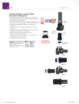
A/C Hose Connections and Routing Requirements
IImmppoorrttaanntt:: See “Refrigerant Hose and Fittings Standards” in Section 8 of the Thermo King TriPac Installation and
Standards Guide (TK 56498). THESE STANDARDS MUST BE FOLLOWED!
• Keep all the A/C fittings capped and sealed until the installation of the refrigeration hoses. Refrigerant oil is
extremely hygroscopic and a system left open for more than 5 minutes may require extensive evacuation/
dehydration time to remove moisture.
• Only cut refrigerant hoses with the correct hose cutting tool (204-677). NEVER USE A SAW!
• Always use the correct hose fitting tool (204-1045) when assembling refrigeration hoses.
• Always lubricate hose fittings with Alkyl Benzene Refrigerant Oil (670404TKA) when assembling to refrigeration
hoses.
• Always install and lubricate O-rings with Alkyl Benzene Refrigerant Oil (670404TKA) when connecting refrigeration
hose fittings to component connection fittings.
• Refrigeration hoses should be installed onto components in such a way as to allow for vibration and movement of
the cab. THEY SHOULD NEVER BE STRETCHED TIGHT!
• All refrigeration connections should be tightened securely using two wrenches.
• Always keep refrigeration hoses from rubbing or chafing against sharp metal objects, rotating components or hot
components.
• Protective covers or sleeves (installer supplied) for the refrigeration hoses may be required depending on the
installation.
• Always install the condenser’s receiver drier so refrigerant flow is in the direction indicated by the arrow.
• Thermo King Evacuation Station (204-725) and Evacuation Station Operation and Field Application Instructions (TK-
40612) are recommended.
• The oil in the evacuation station vacuum pump should be changed after each use.
• The A/C system must be leak free. Check for leaks by using an electronic leak detector.
• The A/C system will be charged with 2.0 lbs. of R134a refrigerant. NNOOTTEE:: AAccccuurraaccyy iiss iimmppoorrttaanntt.. OOvveerr oorr uunnddeerr
cchhaarrggee bbyy 33 oouunncceess wwiillll rreedduuccee ccoooolliinngg ccaappaacciittyy..
TTiippss FFoorr aa SSuucccceessssffuull IInnssttaallllaattiioonn

TK 57249-19-IM-EN 11
Electrical Wiring and HMI Controller Installation Requirements
IImmppoorrttaanntt:: See “Electrical Standards“ in Section 10 of the Thermo King TriPac Installation and Standards Guide (TK
56498). THESE STANDARDS MUST BE FOLLOWED!
• Electrical wiring should be installed and routed in such a way as to allow for vibration and movement of the cab.
THEY SHOULD NEVER BE STRETCHED TIGHT!
• Always keep electrical wiring from rubbing or chafing against sharp metal objects, rotating components or hot
objects.
• All electrical wiring should be neatly routed and secured with band wraps or clamps.
• Do note route or bundle 110Vac wires together with 12Vdc wires.
• Do not route electrical wires, harness or battery cables together with fuel lines.
• Excess length of battery cables should be cut off to reduce voltage drop.
• Superlube (203-524) or equivalent should be applied to all electrical connections.
• All main power and ground accessory connections must be installed directly on top of the truck’s battery terminal
posts and tightened securely. DO NOT INSTALL UNDER OEM BATTERY CABLES!
D2 / D4 Heater Installation Requirements (Units with Heat Option)
IImmppoorrttaanntt:: See “Heater Installation Standards” in Section 7 of the Thermo King TriPac Installation and Standards
Guide (TK 56498). THESE STANDARDS MUST BE FOLLOWED!
• Determine the best location of the heater inside the sleeper, typically under the bunk. Allow clearance for
dismantling for service.
• Install heater so it will maintain a minimum distance of 2.00 inches (50.8 mm) from any heat sensitive or flammable
material.
• The heater must only be mounted on a flat horizontal surface.
• Heater must be installed flush with the floor pan (i.e. sheet metal, fiberglass, etc.) to ensure proper sealing of the
mounting plate and gasket.
• All edges of access holes made in fiberglass and wood composite floors must be sealed correctly with (installer
supplied) fiberglass cloth and resin.
• Outside air intake and exhaust hoses must be installed correctly for the heater to operate safely.
• Exhaust hose should be mounted slightly downwards to help drain off condensation.
• Install exhaust hose so it will maintain a minimum distance of 2.00 inches (50.8 mm) from any heat sensitive or
flammable material.
• Inside air inlet and outlet ducts must be installed correctly for the heater to operate safely.
• Pulse type fuel pump outlet must be installed at a 15 to 35 degree angle up from horizontal to operate correctly.
• Fuel pickup tube must be installed correctly in the fuel tank or the heater will not operate.
• Fuel line from the pickup tube to the fuel pump to the heater should be routed at a continuous rise. Use a hose cutter
or sharp knife to cut plastic fuel lines. Do not use a wire cutter as this will pinch the plastic fuel line closed.
• Do not route electrical wires, harness or battery cables together with fuel lines.
• BEFORE operating the heater, the fuel lines must be bled of air using the Heater Priming Harness (204-1144) or
damage to the fuel pump will result.
• The Diagnostic Code Reader (204-1143) must be used to setup and operate the heater in the run-in mode.
TTiippss FFoorr aa SSuucccceessssffuull IInnssttaallllaattiioonn

12 TK 57249-19-IM-EN
Auxiliary Power Accessories Requirements
Envidia 2 installations may also include optional auxiliary power accessories such as:
• DC/AC Power Inverter
• AC/DC Shore Power Converter
• Solar Panel(s)
When installing any of these power accessories, they must be connected OONNLLYY to the tractor’s batteries per the
installation instructions.
IImmppoorrttaanntt:: DDOO NNOOTT connect auxiliary power accessories to the TriPac Envidia 2 batteries.
TTiippss FFoorr aa SSuucccceessssffuull IInnssttaallllaattiioonn

TK 57249-19-IM-EN 13
Required Tools and Additional Supplies
NNoottee:: While basic mechanics tools and refrigerant service equipment are a necessity, there are also special tools that
are required when installing Thermo King TriPac Units. For a complete listing of special tools, See “Special Tool
Requirements” Section 3 of the Thermo King TriPac Installation Standards Guide (TK 56498).
RREEQQUUIIRREEDD TTOOOOLLSS
1. Floor Jack or Motorcycle/ATV Lift
2. Drill Motor and Drill Bit Set
3. 7/8" dia. or 1" Step Reamer (for evaporator drain and controller holes)
4. Hole Saws
a. 1" dia. (for fuel tank pickup tube)
b. 2-1/2" dia. (for heater inlet/outlet louver)
c. 2" dia. (standard size for access hole for evaporator hoses and electrical wiring)
d. 3” dia. (optional size for access hole for evaporator hoses and electrical wiring)
e. 4-1/4" dia. (for mounting A/C louvers, routing A/C ducts, and and heater mounting hole)
5. Reciprocating Saw (return air opening)
6. 1/2" Wrench
7. Level
8. Tape Measure
9. Utility Knife
10. Caulk Gun
11. Digital Meter (204-1079)
12. Refrigerant Leak Detector (204-712)
13. Hose Fitting Tool (204-1045)
14. Hose Cutting Tool (204-677)
15. Heater Priming Harness (204-1144)
16. Shop Vacuum
17. R-134a Gauge Manifold with automotive connectors
18. Vacuum Pump (204-713)
19. Micron Gauge (204-720)
20. Accurate Refrigerant Scale
21. AGM Battery Tester (204-1959)
22. Heavy Duty AGM Battery Charger (204-1923)
23. Laptop Computer (IBM Compatible) with Microsoft Internet Explorer 10.0 or higher installed.
24. USB Adapter Cable (204-2000)

14 TK 57249-19-IM-EN
AADDDDIITTIIOONNAALL SSUUPPPPLLIIEESS ((aass rreeqquuiirreedd))
1. RTV Silicone Sealant
2. Sealer Tape (203-391)
3. Alkyl Benzene Refrigerant Oil (670404TKA for lubricating hose fittings and O-rings)
4. Refrigerant 134a
5. Return air wall louver (approximately 11” x 10”)
6. Band Wraps (assorted sizes and lengths)
7. Mounting Clamps #24 and #32 (to secure cables and hoses)
8. Upholstery cleaner
9. Cardboard or blankets (to protect truck interior)
10. Fiberglass repair kit (only used for fiberglass and wood composite floor)
RReeqquuiirreedd TToooollss aanndd AAddddiittiioonnaall SSuupppplliieess

TK 57249-19-IM-EN 15
TriPac Envidia and Envidia 2 Component Dimensions
Battery Box Dimensions


/