Thermo King TriPac User manual
- Type
- User manual

Operator’s Manual
Ingersoll Rand’s Climate Solutions sector delivers energy-effi cient HVACR solutions for
temperature control and Trane, a provider of energy effi cient heating, ventilating and
Ingersoll Rand’s Climate Solutions sector delivers energy-effi cient HVACR solutions for
temperature control and Trane, a provider of energy effi cient heating, ventilating and
Printed in U.S.A.
Printed in U.S.A.
TriPac™
Auxiliary Heating/Cooling
Temperature Management System
TK 53035-19-OP (Rev. 6, 12/11)


Copyright© 2005 Thermo King Corp., Minneapolis, MN, USA
Printed in USA
TriPac Auxiliary
Heating/Cooling
Temperature
Management
System
TK 53035-19-OP (Rev. 6, 12/11)

2
Disclaimer
This manual is published for informational purposes only. Thermo King Corporation makes no
representations or warranties, express or implied, with respect to the information, recommendations
and descriptions contained in this manual and such information, recommendations and descriptions
should not be regarded as all-inclusive or covering all contingencies. In the event you have any
questions or require further information, please contact your local Thermo King dealer.
The procedures described herein should only be undertaken by suitably qualified personnel. Failure to
implement these procedures correctly may cause damage to the Thermo King unit or other property or
personal injury.
Thermo King Corporation and its affiliates shall have no liability in contract or tort (including negligence
and/or strict liability) or otherwise, to any person or entity for any personal injury, property damage or
any other direct, indirect, special or consequential damage or liability whatsoever, arising out of or
resulting from any actions by any person that are contrary to this manual or any of the information,
recommendations or descriptions contained herein or the failure of any person to implement the
procedures described herein correctly or to follow caution and safety decals located on the Thermo
King unit.

Table of Contents
1
Table of Contents
Introduction . . . . . . . . . . . . . . . . . . . . . . . . . . . . . . . . . 5
Safety Precautions . . . . . . . . . . . . . . . . . . . . . . . . . . . 7
Refrigerant Oil . . . . . . . . . . . . . . . . . . . . . . . . . . . . . . . . 8
Refrigerant . . . . . . . . . . . . . . . . . . . . . . . . . . . . . . . . . . 8
First Aid . . . . . . . . . . . . . . . . . . . . . . . . . . . . . . . . . . . . . 9
First Aid—Refrigerant . . . . . . . . . . . . . . . . . . . . . . . 9
First Aid—Refrigerant Oil . . . . . . . . . . . . . . . . . . . . 9
Safety Decals . . . . . . . . . . . . . . . . . . . . . . . . . . . . . . . 10
Unit Description . . . . . . . . . . . . . . . . . . . . . . . . . . . . 11
Introduction . . . . . . . . . . . . . . . . . . . . . . . . . . . . . . . . . 11
Unit Features . . . . . . . . . . . . . . . . . . . . . . . . . . . . . . . 12
TriPac System . . . . . . . . . . . . . . . . . . . . . . . . . . . . . . . 12
Auxiliary Power Unit . . . . . . . . . . . . . . . . . . . . . . . . . . 13
Condenser . . . . . . . . . . . . . . . . . . . . . . . . . . . . . . . . . 13
Evaporator . . . . . . . . . . . . . . . . . . . . . . . . . . . . . . . . . 14
Heater . . . . . . . . . . . . . . . . . . . . . . . . . . . . . . . . . . . . . 14
HMI Controller . . . . . . . . . . . . . . . . . . . . . . . . . . . . . . . 15
Compressor . . . . . . . . . . . . . . . . . . . . . . . . . . . . . . . . 15
Control Circuits . . . . . . . . . . . . . . . . . . . . . . . . . . . . . .15
Refrigerant . . . . . . . . . . . . . . . . . . . . . . . . . . . . . . . . . .16
Protection Devices . . . . . . . . . . . . . . . . . . . . . . . . . . . .16
Engine Reset Switch . . . . . . . . . . . . . . . . . . . . . . . . . .17
Closed Loop Cooling Option . . . . . . . . . . . . . . . . . . . .17
Manual Pretrip Inspection (Before Starting the
TriPac Unit) . . . . . . . . . . . . . . . . . . . . . . . . . . . . . . . . .21
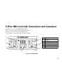
TriPac HMI Controller Description and .Operation 23
TriPac HMI Controller Description . . . . . . . . . . . . .24
HMI Controller Display . . . . . . . . . . . . . . . . . . . . .24
Main Power Key . . . . . . . . . . . . . . . . . . . . . . . . . .24
Mode Key . . . . . . . . . . . . . . . . . . . . . . . . . . . . . . .24
Up and Down Arrow Keys . . . . . . . . . . . . . . . . . . .24
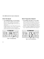
Fan Speed Key . . . . . . . . . . . . . . . . . . . . . . . . . . .25
APU System Key . . . . . . . . . . . . . . . . . . . . . . . . . .25
System Fault Indicator . . . . . . . . . . . . . . . . . . . . . .25
Operating Modes . . . . . . . . . . . . . . . . . . . . . . . . . . . . .26
Air Conditioning Mode . . . . . . . . . . . . . . . . . . . . . .26

Table of Contents
2
Heat Mode . . . . . . . . . . . . . . . . . . . . . . . . . . . . . . 26
Fan Mode . . . . . . . . . . . . . . . . . . . . . . . . . . . . . . . 26
Monitor (Null) Mode . . . . . . . . . . . . . . . . . . . . . . . 26
Engine On/Off Switch . . . . . . . . . . . . . . . . . . . . . . . . . 27
TriPac HMI Controller Operation . . . . . . . . . . . . . . . . . 28
Press HMI Controller Main Power Key . . . . . . . . . 28
Enable APU System . . . . . . . . . . . . . . . . . . . . . . . 28
Engine Hourmeter Display . . . . . . . . . . . . . . . . . . 29
Select Mode of Operation . . . . . . . . . . . . . . . . . . . 29
Select Fan Speed . . . . . . . . . . . . . . . . . . . . . . . . . 30
Select Temperature Setpoint . . . . . . . . . . . . . . . . 30
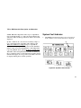
System Fault Indicator . . . . . . . . . . . . . . . . . . . . . 31
Alarm Codes . . . . . . . . . . . . . . . . . . . . . . . . . . . . . 32
To Clear Alarm Codes . . . . . . . . . . . . . . . . . . . . . 32
Optional Standby Operation . . . . . . . . . . . . . . . . . 33
Options Used With Standby Operation . . . . . . . . . 33
Standby Truck Integration . . . . . . . . . . . . . . . . . . . 33
Truck Integration Selector Switch . . . . . . . . . . . . . 33
Optional Power Inverter . . . . . . . . . . . . . . . . . . . . . . 35
Inverter Operation Warnings . . . . . . . . . . . . . . . . . 35
Specifications . . . . . . . . . . . . . . . . . . . . . . . . . . . . . . 37
Engine Specifications . . . . . . . . . . . . . . . . . . . . . . . . . 37
Compressor . . . . . . . . . . . . . . . . . . . . . . . . . . . . . . . . 40
R-134a Refrigeration System . . . . . . . . . . . . . . . . . . . 40
Fuses . . . . . . . . . . . . . . . . . . . . . . . . . . . . . . . . . . . . . 41
Belt Tension . . . . . . . . . . . . . . . . . . . . . . . . . . . . . . . . 43
Truck Sleeper Compartment Heater (D2) . . . . . . . . . 44
Optional Power Inverter . . . . . . . . . . . . . . . . . . . . . . . 48
Optional Extreme Arctic Package Components . . . . . 48
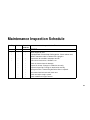
Maintenance Inspection Schedule . . . . . . . . . . . . . 49
Engine . . . . . . . . . . . . . . . . . . . . . . . . . . . . . . . . . . . . 49
Engine Oil Change Intervals ( . . . . . . . . . . . . . . . . . . . 50
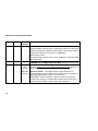
Electrical . . . . . . . . . . . . . . . . . . . . . . . . . . . . . . . . . . . 51
Structural . . . . . . . . . . . . . . . . . . . . . . . . . . . . . . . . . . 52
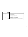
A/C System . . . . . . . . . . . . . . . . . . . . . . . . . . . . . . . . . 53
Heater . . . . . . . . . . . . . . . . . . . . . . . . . . . . . . . . . . . . . 53
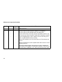
TriPac Warranty . . . . . . . . . . . . . . . . . . . . . . . . . . . . 55
Serial Number Locations . . . . . . . . . . . . . . . . . . . . . 57
TriPac Glossary . . . . . . . . . . . . . . . . . . . . . . . . . . . . 59
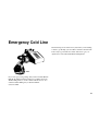
Emergency Cold Line . . . . . . . . . . . . . . . . . . . . . . . . 63

Table of Contents
3
Recover Refrigerant . . . . . . . . . . . . . . . . . . . . . . . . . 64
CALIFORNIA Proposition 65 Warning . . . . . . . . . . . 65

Table of Contents
4

Introduction
5
Introduction
There is nothing complicated about operating and maintaining
your Thermo King unit, but a few minutes studying this
manual will be time well spent.
Performing pre-trip checks and enroute inspections on a
regular basis will minimize on-the-road operating problems. A
regular maintenance program will also help to keep your unit
in top operating condition. If factory recommended procedures
are followed, you will find that you have purchased the most
efficient and dependable temperature control system available.
All service requirements, major and minor, should be handled
by a Thermo King dealer for four very important reasons:
• They are equipped with the factory recommended tools to
perform all service functions
• They have factory trained and certified technicians
• They have genuine Thermo King replacement parts
• The warranty on your new unit is valid only when the
repair and replacement of component parts is performed
by an authorized Thermo King dealer.
IMPORTANT: This manual is published for informational
purposes only and the information furnished herein should
not be considered as all-inclusive or meant to cover all
contingencies. If more information is required, consult your
Thermo King Service Directory for the location and
telephone number of the local dealer.

Introduction
6

7
Safety Precautions
Thermo King recommends all services be performed by a
Thermo King dealer. However, there are several general safety
practices you should be aware of:
DANGER: Always turn the TriPac Main Power
On/Off Key on the HMI Controller OFF while
refueling the truck. Fuel vapors could ignite if they
come in contact with TriPac electrical or heater
components.
WARNING: Always wear goggles or safety glasses
when working with or around the air conditioning
system or battery. Refrigerant or battery acid can
cause permanent damage if it comes in contact with
your eyes.
WARNING: Keep hands and loose clothing clear of
fans and belts at all times when the unit is operating
or when opening or closing compressor service
valves.
WARNING: Exposed coil fins can cause painful
lacerations. Service work on the evaporator or
condenser coils is best left to a certified Thermo King
technician.
CAUTION: Use extreme caution when drilling holes
in the unit. Drilling into electrical wiring or
refrigerant lines could cause a fire. Never drill into
structural components.
WARNING: Turn the unit HMI Controller Main
Power key to Off before opening the APU or
inspecting any part of the unit.

Safety Precautions
8
Refrigerant Oil
Observe the following precautions when working with or
around refrigerant oil:
Refrigerant
Although fluorocarbon refrigerants are classified as safe,
observe caution when working with refrigerants or around
areas where they are being used in the servicing of your unit.
WARNING: Always wear goggles or safety glasses to
protect eyes from refrigerant oil contact.
WARNING: Protect skin and clothing from
prolonged or repeated contact with refrigerant oil.
Rubber gloves are recommended.
WARNING: Wash thoroughly immediately after
handling refrigerant oil to prevent irritation.
DANGER: Fluorocarbon refrigerants may produce
toxic gases. In the presence of an open flame or
electrical short, these gases are severe respiratory
irritants CAPABLE OF CAUSING DEATH.
DANGER: Fluorocarbon refrigerants tend to
displace air and can cause oxygen depletion which
could result in DEATH BY SUFFOCATION. Provide
adequate ventilation in enclosed or confined areas.
WARNING: Fluorocarbon refrigerants evaporate
rapidly, freezing anything they contact if accidentally
released into the atmosphere from the liquid state.

Safety Precautions
9
First Aid
First Aid—Refrigerant
Eyes: For contact with liquid, immediately flush eyes with
large amounts of water. Seek prompt medical attention.
Skin: Flush areas with large amounts of warm water. Do not
apply heat. Wrap burns with dry, sterile, bulky dressing to
protect from infection or injury. Seek prompt medical
attention.
Inhalation: Move victim to fresh air and restore breathing if
necessary. Stay with victim until emergency personnel arrive.
First Aid—Refrigerant Oil
Eyes: Immediately flush eyes with large amounts of water for
at least 15 minutes while holding the eyelids open. Get prompt
medical attention.
Skin: Remove contaminated clothing. Wash thoroughly with
soap and water. Get medical attention if irritation persists.
Inhalation: Move victim to fresh air and restore breathing if
necessary. Stay with victim until emergency personnel arrive.
Ingestion: Do not induce vomiting. Immediately contact
local poison control center or physician.

Safety Precautions
10
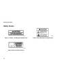
Safety Decals
Figure 1: Caution - Unit May Start Automatically
Figure 2: Belt and Pulley Warning
Figure 3: Shut Off Before Fueling Warning
AMA647
AMA646
AMA690

11
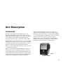
Unit Description
Introduction
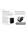
The Thermo King TriPac Auxiliary Heating & Cooling
Temperature Management System allows drivers to reduce
unnecessary truck engine idling, conserve diesel fuel and save
money. TriPac provides truck engine preheating, battery
charging and truck cab sleeper compartment climate control.
By using TriPac, drivers can reduce fuel cost, rest comfortably
during stops and comply with local, state and federal anti-idle
laws. Reducing unnecessary truck engine idling also reduces
engine wear and extends engine maintenance intervals.
TriPac’s own diesel engine uses an automatic start/stop feature
for additional fuel efficiency.
TriPac’s two-cylinder diesel engine is EPA Tier 2 approved.
An automotive type air conditioning compressor is used for
sleeper compartment cooling. A fuel-fired air heater provides
sleeper compartment heat in cold conditions. Voltage sensing
automatically charges the truck batteries from TriPac’s 12-volt
alternator. Noise dampening construction assures quiet
operation. Truck engine preheating provides easier cold-
climate starts by exchanging coolant between TriPac and the
truck engine. Optional Closed Loop Cooling allows the TriPac
to operate independently of truck engine coolant. An optional
inverter provides 120-volt power to operate on-board
appliances. The optional Arctic package aids truck engine
startups in cold weather by sensing low coolant temperature.
The TriPac is started to heat the coolant as required.
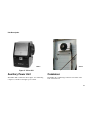
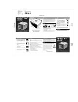
Figure 4: TriPac
AMA691

Unit Description
12
Unit Features
• Easy to operate Human Machine Interface (HMI)
Controller
• Truck cab sleeper compartment cooling and heating for
driver comfort in all climates
• Truck engine preheating for easy starts in cold climates
• Truck battery charging with automatic low voltage sensing
• 7.5 hp 2 cylinder diesel engine - EPA Tier II
• Thermo King TM-15-XD compressor for air conditioning
• Diesel fuel-fired sleeper compartment air heater
• 65 amp 12 VDC alternator
• Noise-dampening construction for quiet operation
• Automatic start/stop operation for maximum fuel
efficiency
• Optional Standby Truck Integration
• Optional dash mounted Truck Integration Selector Switch
(select normal or standby operation)
• Optional Arctic Package
• Optional Closed Loop Cooling (CLC)
• Optional Extreme Arctic Package
• Optional 12 Vdc to 120 Vac 1800 Watt inverter for
on-board appliances
• Optional chrome plated exhaust pipe
• Optional stainless steel condenser shroud
• Optional Exhaust Diesel Particulate Filter (DPF)
TriPac System
The TriPac system includes several major components:
• An APU (auxiliary power unit)
• Condenser
• Evaporator
• Heater
• HMI Controller.

Unit Description
13
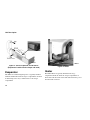
Figure 5: TriPac APU
Auxiliary Power Unit
The TriPac APU contains the diesel engine, air conditioning
compressor, alternator and engine power switch.
Figure 6: Condenser
Condenser
The TriPac Air Conditioning Condenser is mounted on the
back of the truck cab.
AMA691
AMA550

Unit Description
14
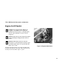
Figure 7: TriPac Evaporator and Air Ducts
(Evaporator installed under sleeper cab bunk)
Evaporator
The TriPac air conditioning Evaporator is typically installed
under the bunk in the truck cab sleeper compartment. Air ducts
from the Evaporator carry conditioned air to the sleeper
compartment
Figure 8: Heater
Heater
The TriPac Heater is typically installed in the cargo
compartment under the truck cab sleeper compartment. It
draws fuel from the truck’s diesel fuel tank and electric power
from the truck’s batteries.
AMA774
AMA653
AMA552

Unit Description
15
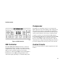
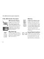
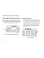
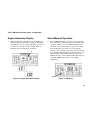
Figure 9: HMI Controller
HMI Controller
The TriPac HMI (Human Machine Interface) Controller is
installed in the truck cab, typically on a wall in the sleeper
compartment. It is easily accessible to the driver and controls
TriPac operation. Standard, typically used operating
parameters are enabled in the HMI Controller when TriPac is
installed. If necessary, HMI operating parameters can be
adjusted through programming by your Thermo King dealer.
Compressor
The TriPac air conditioning compressor is mounted in the
TriPac APU and is driven by the TriPac engine. Refrigeration
lines connect the compressor to the TriPac air conditioning
condenser on the back wall of the truck cab and the evaporator,
usually mounted under the truck sleeper compartment bunk.
Compressor operation is controlled by the TriPac Interface
Board. The Interface Board receives instructions from the HMI
Controller. The HMI Controller will instruct the Interface
Board to start the TriPac engine and energize the compressor
clutch when cab cooling is needed. The refrigeration system is
protected by high pressure and low pressure cutout switches.
Control Circuits
The control circuits operate on 12V DC supplied by the truck
batteries.

Unit Description
16
Refrigerant
The TriPac uses R-134a refrigerant.
Protection Devices
The High System Pressure Cutout Switch is a normally
closed system pressure sensitive switch. On models
manufactured prior to 9/06, it is part of the binary pressure
switch, mounted on the receiver-drier, typically near the TriPac
condenser. On models manufactured during 9/06 and after, a
High Pressure Cutout Switch (HPCO) is located at the
receiver/drier.
If the discharge pressure rises above the switch’s opening
pressure, the switch opens the circuit to stop the unit and
generates an AcS Alarm Code. When the discharge pressure
falls below the switch’s closing pressure, the switch closes to
allow compressor operation.
The Low System Pressure Cutout Switch is a normally
closed pressure sensitive switch.
On models manufactured prior to 9/06, it is part of the binary
pressure switch, mounted on the receiver-drier, typically near
the TriPac condenser. On models manufactured during 9/06
and after, a Low Pressure Cutout Switch (LPCO) is installed at
the evaporator coil.
If the pressure falls below the switch’s opening pressure, the
switch opens the circuit to stop the compressor. When the
pressure rises above the switch’s closing pressure, the switch
closes to allow compressor operation.
Page is loading ...
Page is loading ...
Page is loading ...
Page is loading ...
Page is loading ...
Page is loading ...
Page is loading ...
Page is loading ...
Page is loading ...
Page is loading ...
Page is loading ...
Page is loading ...
Page is loading ...
Page is loading ...
Page is loading ...
Page is loading ...
Page is loading ...
Page is loading ...
Page is loading ...
Page is loading ...
Page is loading ...
Page is loading ...
Page is loading ...
Page is loading ...
Page is loading ...
Page is loading ...
Page is loading ...
Page is loading ...
Page is loading ...
Page is loading ...
Page is loading ...
Page is loading ...
Page is loading ...
Page is loading ...
Page is loading ...
Page is loading ...
Page is loading ...
Page is loading ...
Page is loading ...
Page is loading ...
Page is loading ...
Page is loading ...
Page is loading ...
Page is loading ...
Page is loading ...
Page is loading ...
Page is loading ...
Page is loading ...
Page is loading ...
Page is loading ...
Page is loading ...
Page is loading ...
-
 1
1
-
 2
2
-
 3
3
-
 4
4
-
 5
5
-
 6
6
-
 7
7
-
 8
8
-
 9
9
-
 10
10
-
 11
11
-
 12
12
-
 13
13
-
 14
14
-
 15
15
-
 16
16
-
 17
17
-
 18
18
-
 19
19
-
 20
20
-
 21
21
-
 22
22
-
 23
23
-
 24
24
-
 25
25
-
 26
26
-
 27
27
-
 28
28
-
 29
29
-
 30
30
-
 31
31
-
 32
32
-
 33
33
-
 34
34
-
 35
35
-
 36
36
-
 37
37
-
 38
38
-
 39
39
-
 40
40
-
 41
41
-
 42
42
-
 43
43
-
 44
44
-
 45
45
-
 46
46
-
 47
47
-
 48
48
-
 49
49
-
 50
50
-
 51
51
-
 52
52
-
 53
53
-
 54
54
-
 55
55
-
 56
56
-
 57
57
-
 58
58
-
 59
59
-
 60
60
-
 61
61
-
 62
62
-
 63
63
-
 64
64
-
 65
65
-
 66
66
-
 67
67
-
 68
68
-
 69
69
-
 70
70
-
 71
71
-
 72
72


Thermo King TriPac User manual
- Type
- User manual
Ask a question and I''ll find the answer in the document
Finding information in a document is now easier with AI
Related papers
-
Thermo King TriPac EVOLUTION User manual
-
-
-
-
-
-
-
-
-
Other documents
-
Ingersoll-Rand Thermo King V-520 MAX 30 User manual
-
Ingersoll-Rand THERMO KING TriPac EVOLUTION Installation guide
-
 Boyel Living AZ46202 User manual
-
Subaru 2004 Legacy User manual
-
Webasto Thermo 90 S User manual
-
-
-
COMPANION COMP10201 Owner's manual
-
Master AC 24 ServiceM 097881 Owner's manual
-
Dometic Duo Therm Cab Comfort Heat Pump For Semi-Sleeper 42044.502_42055.502 Installation guide
