Page is loading ...

1. Verify power is OFF to heater controls.
2. Wire nut one black wire of thermostat to 24 VAC (red) wire.
3. Wire nut the second black wire of the thermostat to the heating device (white)
wire and the fan (green) wire in Electric heat applications.
4. Verify wiring is correct and then apply power.
5. Verify system functions correctly.
* Fan (green) wire must be connected to heat system (white) wire for electric
heat applications.
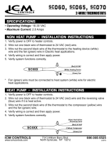
ACH060, ACH065, ACH070
2-WIRE THERMOSTATS
SPECIFICATIONS
• Operating Voltage: 18-30 VAC
• Maximum Current: 2.0 Amps
NON HEAT PUMP – INSTALLATION INSTRUCTIONS
1. Verify power is OFF to heater controls.
2. Wire nut one black wire of thermostat to 24 VAC (red) wire and the reversing valve
(blue) wire if it is heat active.
3. Wire nut the second black wire of the thermostat to the compressor (yellow) wire
and the fan (green) wire.
4. Verify wiring is correct and then apply power.
5. Verify system functions correctly.
HEAT PUMP – INSTALLATION INSTRUCTIONS
LII319-1
www.icmcontrols.com
800-365-5525
ICM CONTROLS
7313 William Barry Blvd.
North Syracuse, NY 13212
1. Verify power is OFF to heater controls.
2. Wire nut one black wire of thermostat to 24 VAC (red) wire.
3. Wire nut the second black wire of the thermostat to the heating device (white)
wire and the fan (green) wire in Electric heat applications.
4. Verify wiring is correct and then apply power.
5. Verify system functions correctly.
* Fan (green) wire must be connected to heat system (white) wire for electric
heat applications.
ACH060, ACH065, ACH070
2-WIRE THERMOSTATS
SPECIFICATIONS
• Operating Voltage: 18-30 VAC
• Maximum Current: 2.0 Amps
NON HEAT PUMP – INSTALLATION INSTRUCTIONS
1. Verify power is OFF to heater controls.
2. Wire nut one black wire of thermostat to 24 VAC (red) wire and the reversing valve
(blue) wire if it is heat active.
3. Wire nut the second black wire of the thermostat to the compressor (yellow) wire
and the fan (green) wire.
4. Verify wiring is correct and then apply power.
5. Verify system functions correctly.
HEAT PUMP – INSTALLATION INSTRUCTIONS
LII319-1
www.icmcontrols.com
800-365-5525
ICM CONTROLS
7313 William Barry Blvd.
North Syracuse, NY 13212
LII319-1.indd 1 2/14/19 8:09 AM
/