Page is loading ...

www.ledalite.compage10/12/2023 1
!ATTENTION: Install in accordance with local and national building and electric codes.
Architectural Linear
System Overview
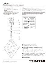
These instructions review how to install SyncLine suspended fixtures. SyncLine 4ft, 6ft, and 8ft modules
can be installed as individual standalone units, or they can be joined together to create a continuous
run. The graphic below shows the components required to install a typical run or a standalone fixture.
ID-SL SyncLine Suspended
SyncLine
10/12/2023 1
SyncLine Endcap Kit
- SL Endcap
- Bushing Strain
- Bushing Plug
- Cable relief
- A/C Cable
- Rubber Gasket
-#8-18 X 3/8 screws (2x)
SyncLine Joint Kit
- SL Locking Plate
- Bushing Strain
- Bushing Plug
- Cable relief
- A/C Cable
- Rubber Gasket
-#8-18 X 3/8 screws (2x)
TOOLS REQUIRED: Phillips screwdriver, flat head screwdriver
Module Lengths
SyncLine suspended fixtures come in 4ft, 6ft, and 8ft modules. Overall module lengths are shown below.
Module lengths do not include endcaps.
4' 3/16" 6' 8'
Indicates overall length of the fixture.
(excluding endcaps)
Endcaps
Two endcaps are required per run regardless of the length of the run. One endcap on each end of the run.

page
!ATTENTION: Install in accordance with local and national building and electric codes.
This equipment has been tested and found to comply with the limits for a Class A digital device, pursuant to part 15 of the FCC Rules.
These limits are designed to provide reasonable protection against harmful interreference when the equipment is
operated in a commercial environment. This equipment generates, uses, and can radiate radio frequency energy and, if
not installed and used in accordance with the instruction manual, may cause harmful interference to radio
communications. Operation of this equipment in a residential area is likely to cause harmful interference in which case
the user will be required to correct the interference at his own expense.
Arrange boxed fixtures on floor in specified mounting locations, based on supplied layout drawings. Remove fixtures from boxes. Install all
ceiling mount components and vertical aircraft cables using separate installation instruction for Aircraft Cable Mounting (Supplied).
Note: If conditions are dusty/dirty, recommended practice is to leave fixtures in their plastic bags.
Cut small holes in the bag as needed to complete the following installation sequence, and then completely remove the bag from the fixture
when conditions are clean. This prevents dust and dirt build up on the fixtures.
Prepare Fixtures / Install ceiling mounting components
i
10/12/2023 2
SyncLine Instruction Sheet –Standalone & Continuous Runs
ID-SL
IMPORTANT:
Disconnect or turn off
power before attempting
any installation, service or
maintenance.
Fixture must be connected
to building ground via the
provided ground wire
before re-connecting to
mains power supply.
Power Label Location
Power labels can be found
on top of the light engine
pans. If dustcover is
installed, please remove
before installation of
fixtures.
!
Continuous Run
The fixtures in continuous runs are connected with joiner kits. Each joint and both ends of the run will be
suspended by a sling mount and aircraft cable attached to the ceiling. A continuous run of two 8ft fixtures and
one 4ft fixture is shown below.
Power Feed Locations
Four power feed locations are provided on all lengths: two on each end of the fixture.

page
!ATTENTION: Install in accordance with local and national building and electric codes.
10/12/2023 3
SyncLine Instruction Sheet –Standalone & Continuous Runs
ID-SL
Remove dust cover from the fixture. Lightly
press in the center to disengage it from the
housing.
1
Hook A/C sling mount to endplate as shown.
Raise sling until seated in endplate. Install
on both side of the fixture.
2
In the case of a variable mount, press the
tabs along the sides of the fixture housing
forward and insert A/C sling mount in holes
along the top of the fixture body up to 6”
from the ends. Install on both sides of the
fixture.
3Remove Dust Cover Insert Sling Mount Install Variable Mount
With tabs pressed inwards and variable A/C
mount inserted, ensuring that the mounting
holes are lined up, insert screws as shown
on both sides of the fixture.
4
With two people, raise the first fixture to
the ceiling. At each end of the module,
insert aircraft cable through aircraft cable
sling.
5
NON-POWER LOCATIONS: Cap all wires and
tuck into wire cavity. POWER LOCATIONS:
Remove required 1/2" round knockout(s).
Insert power cord and apply strain relief to
secure cord. Remove installed quick-wire
connectors (if applicable) at power feed
locations and complete electrical
connections using wire nuts (supplied by
others). Tuck wires into wire cavity.
NOTE: Use smallest appropriate wire nuts.
6Install Variable Mount Suspend and Level First
Fixture Complete Electrical
Connection
½” EKO Remove ½” EKO
Strain relief
Wire nuts supplied by others
4

page
!ATTENTION: Install in accordance with local and national building and electric codes.
10/12/2023 4
SyncLine Instruction Sheet –Standalone & Continuous Runs
ID-SL
Cut, peel and stick the gasket to the edge of
the luminaire as shown. Every fixture end or
joint requires gasket installation.
7
Ensure gasket is seated properly. The gasket
should not protrude overall luminaire width
or height.
7.1
The gasket is shown in grey above.
If not joining additional fixture(s), skip to
step 11 for endcap installation instructions.
7.2Gasket Installation Gasket Installation Gasket Installation
For each additional fixture in the row, at the
end furthest from the existing suspended
fixture, attach A/C sling to the fixture (see
steps 2-4). At the end closest to the existing
suspended fixture, pull out the two tabs.
Repeat procedure for the luminaire it will be
joined to.
8
Using a set of pliers, ensure that tabs are
perpendicular to fixture. This is required to
ensure proper engagement to opposite
fixture.
With two people, raise second fixture to
ceiling. At other end (opposite joint), insert
aircraft cable through adjuster. At joint,
insert temporary hooks into suspended
fixture. Ensure temporary hook is engaged
on both fixtures.
IMPORTANT: Do not attempt to join
fixtures on floor. Instead, hang one fixture
at a time and join modules at ceiling level.
8.2
Join additional fixture to
create row
Join additional fixture to
create row Join additional fixture to
create row
PULL/BEND
OUT
Temporary
hook
Pliers
Temporary
hook
Tabs perpendicular to
crossplate
Temporary hooks
8.1
6"39
64(168mm)
1"3
16 (30mm)

page
!ATTENTION: Install in accordance with local and national building and electric codes.
10/12/2023 5
SyncLine Instruction Sheet –Standalone & Continuous Runs
ID-SL
Complete in-row electrical connections.
NON-POWER LOCATIONS: Use supplied
quick-wire connectors. Tuck wires into wire
cavity.
POWER LOCATIONS: Remove installed
quick-wire connectors and complete
electrical connections using wire nuts
(supplied by others). Tuck wires into wiring
cavity.
9
SLIDE MODULES TOGETHER: Drop in the
locking plate provided in the joint kit.
Locking plate will interlock the two fixtures
together.
After the locking plate is inserted, secure
the locking plate to the crossplate. Using a
Philips head screwdriver, tighten screws
until the two fixtures pull together creating
a seamless gap.
11
Complete Electrical
Connections Join additional fixture Secure with locking plate
Cut, peel and stick the gasket to the edge of
the luminaire as shown. Refer to steps 7-7.2
for more instructions.
12
Place the endcap on top of the crossplate.
Align to luminaire.
13Gasket Installation Install Endcaps 14
Using the provide Philips screws (black),
attach endcaps to bracket.
IMPORTANT: Do not over-tighten endcap
fasteners. Signify Ledalite recommends
tightening fasteners by hand. When
screwhead is flush with crossplate, turn an
additional full turn
Install Endcaps
10
Wire nuts
(By others)
Quick-wire
Connectors
(Supplied)
6"39
64(168mm)
1"3
16 (30mm)

page
!ATTENTION: Install in accordance with local and national building and electric codes.
10/12/2023 6
SyncLine Instruction Sheet –Standalone & Continuous Runs
ID-SL
Tuck the dust cover into the fixture.
15
On the power drop side of the luminaire,
trim the dust cover as shown above to clear
the power cord.
16 10Install Dust Cover Install Dust Cover
10.1 11 11.1
.

page10/12/2023 7
Interact Pro Foundation/Advance Install & Setup
PRF/PRA
www.ledalite.com
To configure a lighting system with Interact sensors or RF nodes;
•Ensure the luminaires are installed and powered on.
•Download the Interact Pro app from either Apple’s App Store (for iOS)
or Google’s Play Store.
Interact Pro Foundation
Quick Start Guide
Interact Pro
Documentation
•Register by tapping Request access on the login screen in the app.
•Click or scan the QR codes below to view instructions for setup.
Contact Us
1-800-555-0050
Interact Pro Advanced
Quick Start Guide
Interact Pro
Setup Video
*not for Enterprise or Signify Commissioned projects

page
!ATTENTION: Install in accordance with local and national building and electric codes.
Sensors in Rows
Single Sensor Controlling Whole Row
1. Purple & brown (or purple & grey/pink) control wires MUST be connected between fixtures.
Note:
•A maximum of 8 drivers can be wired to one sensor; confirm fixture driver count with factory.
Sensor
8ft4ft
1
Bottom view of fixtures
Multiple Sensors Controlling Separate Zones in a Row
2. Purple & brown (or purple & grey/pink) control wires MUST NOT be connected between zones.
Notes:
•A maximum of 8 drivers can be wired to one sensor; confirm fixture driver count with factory.
•Only one sensor is allowed on a wired zone. (Sensors can be paired together wirelessly via a mobile app).
Sensor
8ft 4ft
2
Bottom view of fixtures
Sensor Zone 2Zone 1
8ft4ft
Bottom view of fixtures
Sensor Sensors are too close together
for proper operation.
Sensors are at minimum required
distance for correct operation.
Sensors are at a maximum
distance of 40ft apart.
Sensor
40ft Max.
Sensor Sensor
Sensor Spacing
•For correct operation, sensors should be placed a minimum distance of 8ft apart.
•Wireless sensors should be placed no further than 40ft apart for good wireless signal connection.
Important Consideration When Using Sensors in a Row
•For fixtures with wireless sensors (CS, SB or RA options):
DO NOT connect fixture purple & brown (or purple & grey/pink) control wires to an external dimming switch.
Fixture mains wiring should not be connected to a circuit with an external on/off switch.
•For best aesthetic condition, place sensors at ends of row only so as not to break the continuous lens.
•For better occupancy coverage in longer rows, sensors may be placed mid run, but keep in mind this will
break the continuous lens into discrete sections.
Sensor
8ft 4ft
Bottom view of fixtures
Sensor Zone 2Zone 1
Bottom view of fixtures
10/12/2023 8

page www.signify.com
!ATTENTION: Install in accordance with local and national building and electric codes.
Daylight sensor
The light sensor measures the total amount of light in
a circular field of approximately 80% of the PIR
detection area. The following aspects should be
observed during installation:
• Minimum distance from the window ≥2ft (0.6m).
• Prevent light reflections from outside entering the
sensor (for example sunlight reflection on a car
hood) as this will lead to incorrect light regulation.
As a guideline the formula 0.72 x H can be used to
calculate the minimum distance between the window
and sensor whereby H is the height from the bottom
of the window to the sensor.
Occupancy Sensor Coverage:
Note: Longer dimension of detection area (Y1, Y2) is
parallel to longer dimension of the luminaire.
The detection area for the movement sensor can be
roughly divided into two parts:
• Minor movement (person moving ≤3ft/s or 0.9m/s).
• Major movement (person moving ≥3ft/s or 0.9m/s).
Photosensor spatial response
10/12/2023 9
/