Page is loading ...

©2009 McQuay International
®
Note: Installation and maintenance are to be performed only by qualied personnel who are familiar with local codes and regula-
tions and are experienced with this type of equipment. Caution: Sharp edges and coil surfaces are potential injury hazards.
Installation & Maintenance Data IM 950-1
Group: PTAC
Part Number: 669548801
Date: February 2009
PDAE/PDHE 16" x 44" Replacement Unit
Comfort Conditioner

IM 950-1 / Page 2 of 38
Now that you have made an investment in modern, efcient McQuay
®
equipment, its care and operation should
be a high priority. For training information on all McQuay HVAC products, please visit us at www.mcquay.com and
click on Training or phone 540-248-0711 and ask for the Training Department.
Table of Contents
Safety Information .......................................................3
Inspection .....................................................................3
Nomenclature ...............................................................4
Dimensional Data .......................................................5
W
all Opening Requirements ..................................6
Installation Considerations ....................................7
Preparing the Unit for Installation ...........................8
Installation of: ...........................................................8
Louver Frame ........................................................8
Cabinet/W
all Sleeve Extension .............................8
Optional Condensate Drain Kit .............................9
Room Cabinet/Wall Sleeve .............................10-11
Heating/Cooling Chassis .....................................12
Heat Fan Lock Out Control .................................12
Equipment Start-up ..............................................13
Start-up Report–Audit .........................................14
Contr
ols ..............................................................15-26
Standard Digital
Touchpad Control ................15-17
Modes of Operation ........................................17-21
Premium (Programmable) Digital
T
ouchpad Control Operating Instructions ......22-24
Remote
Wall Mounted Thermostats ...............25-27
Wiring Diagrams .................................................27-31
Remote
Thermostat With Secondary Units .........27
Premium (Programmable)
Digital Control Board ..........................................
28
Standard (Non-programmable)
Digital Control Board ..........................................
29
Digital Control Board
With Standby Power ........30
Digital Control Board
Without Standby Power ...31
Scheduled Maintenance ........................................32-33
Faults and Protection Codes for
PTAC/PTHP Control Board .......................................34
Solid State Digital Controls-LUI Interface
Display Codes ............................................................34
Troubleshooting Chart ..........................................35-36
Approximate Shipping Weights .................................37

IM 950-1 / Page 3 of 38
WARNING
The installer must determine and follow all applicable
codes and regulations. This equipment presents hazards
of electricity, rotating parts, sharp edges, heat and weight.
Failure to read and follow these instructions can result in
property damage, severe personal injury or death. This
equipment must be installed by experienced, trained
personnel only.
Safety Information
Follow all safety codes. Wear safety glasses and
work gloves. Use a quenching cloth for brazing
operations. Have a re extinguisher available. Follow
all warnings and cautions in these instructions and
attached to the unit. Consult applicable local building
codes and National Electrical Codes (NEC) for special
requirements.
Recognize safety information. When you see a
safety symbol on the unit or in these instructions, be
alert to the potential for personal injury. Understand
the meanings of the words DANGER, WARNING,
and CAUTION. DANGER identies the most serious
hazards that will result in death or severe personal
injury; WARNING means the hazards can result in
death or severe personal injury; CAUTION identies
unsafe practices that can result in personal injury or
product and property damage.
Improper installation, adjustment, service,
maintenance, or use can cause explosion, re,
electrical shock, or other conditions which may result
in personal injury or property damage. This product
must be installed only by personnel with the training,
experience, skills, and applicable licensing that makes
him/her “a qualied professional HVACR installer.”
IMPORTANT
This product was carefully packed and thoroughly
inspected before leaving the factory. Responsibility
for its safe delivery was assumed by the carrier upon
acceptance of the shipment. Claims for loss or damage
sustained in transit must therefore be made upon the
carrier, as follows:
VISIBLE
LOSS OR DAMAGE
Any external evidence of loss or damage must be noted
on the freight bill or carrier’s receipt, and signed by the
carrier’s agent. Failure to adequately describe such
external evidence of loss or damage may result in the
carrier’s refusal to honor a damage claim. The form
required to le such a claim will be supplied by the carrier.
CONCEALED
LOSS OR DAMAGE
Concealed loss or damage means loss or damage which
does not become apparent until the product has been
unpacked. The contents may be damaged in transit due
to rough handling even though the carton may not show
external damages. When the damage is discovered upon
unpacking, make a written request for inspection by the
carrier’s agent within fteen (15) days of the delivery
date. File a claim with the carrier since such damage is
the carrier’s responsibility.
CAUTION
Use copper conductors only. Unit terminals are not
designed to accept other types of conductors.
Failure to do so can damage equipment.
DANGER
Hazardous Voltage!
Disconnect all electric power including remote
disconnects before servicing. Failure to
disconnect power before servicing can cause
severe personal injury or death.
Inspection
When the equipment is received all items should
be carefully checked against the bill of lading to be
sure all crates and cartons have been received. All
units should be carefully inspected for damage when
received. If any damage is noticed, the carrier should
make the proper notation on the delivery receipt
acknowledging the damage. The carrier should also
ll out a carrier Inspection Report. The McQuay Inc.
Trafc Department should then be contacted. The unit
nameplate should be checked to make sure the voltage
agrees with the power supply available.
A complete unit consists of the following
components, ordered and shipped separately.
1.
Heating/Cooling Chassis
2. Front Panel.
2. Room Cabinet/Wall Sleeve.
3. Outdoor Louver.
4. Subbase – Optional for 208V and 230V units but
mandatory for all 265V.
5. Fixed heater with factory installed power cord.
6. Electrical receptacle – Required for 208V and
230V units but mandatory for all 265V and
Hydronic units.
7. Plug cord cover – Optional for 208V and 230V
units but mandatory for all 265V.

IM 950-1 / Page 4 of 38
Damper Type
Damper Control
A = Automatic (Required for Hydronic Heat)
M = Manual
Y = None
Unit Type
P = PTAC
Product Identier
PDAE = A/C PMES/EA Replacement
PDHE = H/P PMRS/RS Replacement
Design Series
1 = A Design 1
2 = B Design 2
3 = C Design 3
4 = D Design 4
5 = E Design 5
Unit Size
007 = 7,000
009 = 9,000
012 = 12,000
015 = 15,000
017 = 17,000 (Cooling Only)
Voltage
A = 115-60-1
E = 208/230-60-1
J = 265/277-60-1
P = 208/230-60-1 w/stndy 115-60-1
Brand Name
M = McQuay
Refrigerant
R = R22
Heating Type
E = Electric Heat
H = Hydronic (PDAE only)
Y = None (PDHP only)
Electric Heat
A = 2.5 Kw
B = 3.5 Kw
C = 5.0 Kw
Y = None
Hydronic Heat Type
S = Steam Top Mount (Normally Closed)
H = Hot Water Top Mount (Normally Open)
Y = None
SKU
A = Stock
B = Build to Order
P DAE 1 009 E M R H A B D M A A E
Controls
Control Board Type
B = Basic Control
P = Premium Controls
(Req'd for Hydronic Heat)
User Interface Type
P = Programmable (Unit Mtd. Touchpad)
N = Non-Programmable
(Unit Mtd. Touchpad)
Y = None (Wall Stat with Blank-off Plate)
Room Interface
Cabinet Type
D = 16" x 44" Replacement
Power Connection
L = Long Cord – 72" (Standard)
S - Short Cord – 18" (Optional)
18" Cord, Standard w/Hydronic
Subbase
Y = None
Upgrade Packages
S = Seacoast
Y = None
Warranty
A = Standard
E = Extended
X =Special
McQuay Model PDAE/PDHE Product Nomenclature
Note: For Illustration purposes only. Not all options available with all models.
Please consult a McQuay Sales Representative for specic availability.

IM 950-1 / Page 5 of 38
PDAE – Air Conditioner with Electric Heat / PTHE – Heat Pump with Electric Heat
16
3
/8"
(416mm)
44
7
/8" (1140mm)
41
1
/2" (1054mm)
1
11
/16"
(43mm)
3" (76mm)
or 4" (102mm)
10
1
/2" (267mm)
Minimum
Finished
Wall Line
6
1
/4"
(159mm)
4
1
/4" (108mm)
to 13
3
/4" (349mm)
20" (508mm)
1/2" (13mm)
A
A =
Louver thickness: 3/8" (10mm) stamped,
1
1
/8" (29mm) extruded architectural
Top View
Front View
Side View
Dimensional Data

IM 950-1 / Page 6 of 38
Installation – Considerations
The PDAE/PDHE 16" x 44" Replacement Unit is
designed and built for through-the-wall installation
in either existing or new buildings. Each conditioner
consists of the following components identied in their
typical installation sequence:
1.
Subbase – Optional on 208/230V, standard on 265V,
shipped in its own carton.
2
. Louver Frame – Optional, shipped ve (5) per
carton.
3.
Room Cabinet/Wall Sleeve with Front Panel and
Filter – Shipped in palletized carton.
4. Outdoor Louver – Shipped in its own carton.
IMPORTANT
Air ow required for PTAC units must not be restricted
by exterior plants or walls. Plants or shrubs must not
be planted in close proximity to the outside grille of the
PTAC unit. Vegetation planted too close to grilles will
cause discharge air to be recirculated, thereby increasing
electrical consumption. Warranty will be voided if it is
determined that the compressor life is shortened from
overheating due to close proximity of outside obstructions.
Note: Discharge air restrictions include, but are not
limited to:
• Vegetation
• Concrete walls or barriers
• Overhangs that do not allow discharge air to rise
• Installation of bug screen of any kind
5.
Heating/Cooling Chassis – Shipped in palletized
carton.
Figure 1. Panel Wall (Thin) Construction
Figure 3. Frame and Brick Construction
Figure 2. Masonry Wall (Thick) Construction
16
5
/8" x 45
1
/8"
Cabinet/Wall Sleeve
Rough Opening or
16
7
/8" x 45
3
/8" When using a
Louver Frame
(See page 9 for Installation)
Floor
Concrete
Pillars
Steel Studs
16
3
/8" x 44
7
/8"
Cabinet/Wall Sleeve
Lintel
(by others)
4
5
1
/
8
" Wide
Cabinet/Wall Sleeve
Rough Opening
16
5
/
8
" High
Wall Construction Types
Wall Opening Requirements
The rough opening should measure 16
5
/8" high x
45
1
/8" wide. When using a louver frame, the opening
must measure 16
7
/8" x 45
3
/8". Louver frames should be
used for panel wall and thin wall applications to assure
positive anchoring to the wall (Figure 13). When a
elecrical subbase is used, the opening must start 3"
to 4" above the nished oor (including carpeting) to
match the height of the subbase selected. The subbase
is available in 3" or 4" heights and has adjustable
leveling legs that provide up to an additional 1" height.
A 3" or 4" subbase is required for 265V models and
is optional for 208/230V models.
Wall Sleeve Extension
(See page 9 for
Installation)
Splitters
16
3
/8" x 44
7
/8"
Cabinet/Wall Sleeve
Lintels (by others)
Room Side

IM 950-1 / Page 7 of 38
General Information
Electric Service – All wiring should be done in accor-
dance with local and national electrical codes. Electric
service for the replacement unit is via a receptacle type
outlet furnished with 265V units. 208/230V units are
equipped with a plug and cord set to plug into a recep-
tacle which is supplied by others and eld installed.
The use of an extension cord to increase the length
of the plug/cord set furnished as a part of the unit is not
recommended.
Suggested Outlet Locations
1. Floor Mounted Conditioners – 208/230V units
only. Mount an outlet in the wall to the right or left
of the conditioner (see Figure 4). The chassis’ cord
has a 72 inch usable length from where it exits from
the lower right of the front panel.
2.
Wall Mounted Conditioner – 208/230V units
only. A receptacle is generally mounted beneath
the conditioner on, or recessed in, the wall so it is
concealed by the conditioner overhang (see Figure
5). The chassis’ cord has a 18 inch usable length
from where it exits from the lower right of the front
panel.
44
7
⁄8"
(1140mm)
20"
(508mm)
2
3
⁄4"
(70mm)
4
1
⁄8" (105mm)
8
1
⁄4"
(210mm)
Figure 7. Cabinet/Sleeve Base Pan - Top View
Note: Remove knockout from base pan if subbase is
used.
1
1
⁄2"
(38mm)
Knockout
Fig. 4. Floor-mounted Conditioner
Fig. 6. Conditioner with Subbase
Fig. 5. Wall-mounted Conditioner
3. Conditioner with Subbase – Required with 265V
units, optional with 208/230V units. The subbase
includes an electrical compartment in the right front
corner providing brackets for mounting a receptacle
directly beneath the base pan knockout. There is no
need for a junction box when this method is used
(see Figure 6). Since 265V units require a subbase,
the electrical cord is only long enough to reach a
receptacle in the subbase.
In all cases, excess cord should be rolled up an stored
in the conditioner.

IM 950-1 / Page 8 of 38
Cabinet/Wall Sleeve Extension for Thick Wall
Construction Types
The standard wall sleeve will accommodate a
maximum wall thickness of 10.25." For thicker walls,
wall sleeve extensions are required and are available
from your local representative. When it is supplied by
the representative, it is treated for maximum corrosion
resistance and matched to exact size of the standard
wall/sleeve. Be sure to provide air splitters to prevent
recirculation of condenser air. Air splitters should be
placed in the wall sleeve as shown in gure 9. It is
important that spacing of the air splitters match exactly
those dimensions shown in gure 9.
Cabinet/Wall Sleeve Extension Installation
Wall sleeve extensions are shipped in a separate
carton and tagged to match the proper unit. Be sure to
check tagging of the extension against that of the unit.
Install the wall sleeve extension as follows:
1.
Position the extension with standard wall
sleeve so proper alignment with drain and
mounting holes is achieved.
2. Place a bead of caulk around the perimeter of the
wall sleeve and another bead around the mating
side of the wall sleeve extension so that the joint
is watertight. Do not permit caulking to block the
weep holes. Be sure to use a resilient caulking
such as silicone.
3. Assemble the wall sleeve extension to the wall
sleeve. Clean out weep holes to assure proper
drainage.
4. Attach indoor drain kit (if used) according to the
instructions on page 9. Outdoor drain kits must
be installed to the wall sleeve extension.
5. Continue wall sleeve installation according to
instructions on page 10-11.
Preparing Unit for Installation
Note: rst install the louver frame following steps 1
and 2 as described in "Louver Frame Installation."
Remove the outer carton and inspect the conditioner
for damage. Report any damage found to the carrier.
Note: Save the outer carton for reuse to cover the
installed conditioner until ready for use.
Louver Frame Installation
When a louver frame is used, it must be installed
prior to, or at the same time, as the room cabinet/wall
sleeve, and it must be level and square (see Figure 8).
1.
Apply caulking compound on the surfaces of the
louver frame’s four anges which will come in
contact with the wall. Add caulking as required for
weather tight seal.
2.
Insert the sleeve of the louver frame into the wall
opening from the exterior of the building and apply
rm pressure so that the caulked frame anges are
snug against the exterior of the building. Secure
the louver frame to the wall if desired.
3.
Secure the louver frame to the wall through the
sides and top. Never secure the frame through the
bottom as it may cause leaks.
If the louver frame is to be installed in a panel wall,
it should be installed at the same time as the room cabi-
net/wall sleeve.
Figure 8.
Drill holes &
secure top
& sides
Louver
Frame
Caulk
4
sides
Nut &
washer
5 places
Leveling
bolt
Louver
Cabinet
Sleeve
Subbase
Receptacle
Secure to
Subbase
1
1
⁄16"
Flange
Note: Subbase is optional on 208/230V units, but
required on 265V.
Louver frame is optional on all units.
Figure 9. Wall Sleeve Extension
Wall Sleeve Extension
Room Side
16"
24"
44.50"
Air Splitters
as required
11
7
/8"
7
5
/8"
24"

IM 950-1 / Page 9 of 38
Condensate Drain Kit Installation
Figure 10 illustrates the installation of the indoor
drain kit. The indoor drain kit must be installed before
placing the cabinet/wall sleeve into the opening.
Assembly of the external drain kit should be completed
after the cabinet/wall sleeve has been installed.
Indoor Drain Kit Installation
1. Locate the drain so that it will be on the room side
of the wall when the wall sleeve is installed.
2. Drill a 1/2" diameter hole in the base of the wall
sleeve for the drain.
Alternate 6" Long, 1/2" O.D.
Straight Copper Tube
External Drain Kit
Figure 10. Indoor Drain Kit
Cover
Plate
Tube
Gasket
Screws
1/2"
(13mm) O.D.
Cabinet Bottom
Neoprene Sponge Gasket
Steel Mounting Plate
Indoor Drain Detail
Contractor To Drill Three (3) Holes To Accept
Drain Kit
3. Drill two (2)
5/32" pilot holes for the mounting
screws. These holes can be located using the drain
kit as a pattern.
4. Assemble the drain kit as shown in Figure 10 and
securely fasten it to the wall sleeve with the
screws provided. Use either the 90
o
elbow or 6"
straight tting as required.
5. Install the cabinet/wall sleeve as described on
pages 10-11.
Note: When using the external drain kit, the sleeve
must be ush or beyond the outside nished wall (do
not recess).
External Drain Kit Installation
1. Assemble the drain kit as shown in Figure 11.
2. Choose the side of the cabinet/wall sleeve to which
the drain kit is to be installed.
3. There are drain holes and pilot holes provided in
the wall sleeve from factory. Place the drain kit
against the chosen drain hole and fasten securely
with screws provided. Use either the 90
o
elbow or
6" straight tting as required.
4. Cover the unused drain hole with the block off
plate and gasket supplied with the drain kit.
Indoor Drain Kit
Room Side
Neoprene
Sponge
Gasket

IM 950-1 / Page 10 of 38
Note: Use of 6" straight drain
tube will require modication of
architectural louver.
Neoprene Sponge Gasket
Steel Mounting Plate
1/2" (13mm) O.D. Drain Tube
Alternate 6" Long,
1/2" O.D. Straight Copper Tube
Figure 11. External Drain Kit - installed after the cabinet/wall sleeve has been installed.
Room Cabinet/Wall Sleeve
Installation
Considerations
The cabinet/wall sleeve is a standard size 16
3
/8"
high, 44
7
/8" wide and 20
3
/4" deep. Slide channels
are factory welded into the sleeve to facilitate easy
installation and removal of the chassis.
All necessary fasteners are supplied to assemble the
chassis and the louver to the wall sleeve.
Panel and Thin Wall Applications
The PDAE/PDHE conditioner can be successfully
installed in various ways. However, this instruction is
based on the use of both a subbase and a louver frame.
1.
Install the subbase as described in the section "In-
stallation of Subbase. Also refer to IM 937 shipped
with the subbase.
2.
Install the louver frame as described in the section
“Louver Frame Installation.”
3.
Position the room cabinet/wall sleeve in the louver
frame opening and on the subbase. The rear face
of the cabinet should be recessed from the outside
edge of the louver frame by the depth of the louver
to be installed (see Figure 12).
4.
Level the subbase with leveling bolts provided.
Attach the subbase to the room cabinet/wall sleeve
per instructions provided with the subbase.
5.
After the room cabinet/wall sleeve is leveled side
to side and pitched 1/4 bubble to the outside,
secure the louver frame to the wall with screws
driven through the sides and top of the room cabi-
net/wall sleeve outward through the louver frame.
Never secure the frame through the bottom as it
may cause leaks.
6.
Caulk the outdoor joint between the room cabi-
net/wall sleeve and the louver frame: top, bottom,
and both sides. Do not permit caulking to block the
weep holes.
7.
Install the outdoor louver. Holding the louver with
a wire loop or other similar means, push the louver
out through the rear opening in the room cabinet/
wall sleeve and pull the louver back to the rear
face so that the louver studs pass through the holes
in the room cabinet/wall sleeve ange. Attach the
louver with the washers and nuts provided, and
securely tighten the louver in place.
8.
Cut the shipping carton as necessary to cover the
installed room cabinet/wall sleeve until ready to
use.
Neoprene Sponge Gasket
Room Side
Block off plate and gasket

IM 950-1 / Page 11 of 38
Masonry and Thick Wall Applications
1. Preparation of the wall opening — In new construc-
tion, the room cabinet/wall sleeve can be built into
the building wall as it progresses, or openings can
be left for later installation.
A
lintel by others must be used to support any brick
or masonry work above the conditioner.
2.
Set the room cabinet/wall sleeve in soft mortar and
position it in the wall opening. The rear face of the
conditioner should be recessed from the outside
edge of the wall opening by the depth of the louver
to be installed. When using the anged stamped
louver, the rear ange of the room cabinet/wall
sleeve will be ush with outside edge of the wall
opening. The center of gravity of the conditioner is
9
1
⁄2" from the rear face. For wall-mounted condi-
tioners, the center of gravity must be within the
load bearing portion of the wall; otherwise, sup-
port is required.
3.
Level the room cabinet/wall sleeve side to side and
pitch down 1/4 bubble to outside. Securely fas-
ten the room cabinet/wall sleeve in the wall from
inside the cabinet through the sides and/or top on
the outdoor side of the weather seal. Make sure
the cabinet is not distorted. Never secure through
the bottom of the cabinet. For installations using
a subbase, level the room cabinet/wall sleeve with
leveling bolts provided with the subbase. Attach
the subbase to the room cabinet/wall sleeve per
instructions provided with the subbase.
4.
After the room cabinet/wall sleeve is installed and
leveled side to side and pitched down 1/4 bubble
to the outside, secure it and the louver frame to the
wall with screws driven through the sides and top
of the room cabinet/wall sleeve outward through
the louver frame. Never secure the frame through
the bottom, as it may cause leaks. A
5
⁄32" diameter
hole has been added to each side of the wall sleeve
as a provision for securing the sleeve in the wall
opening. Each hole is located 2" down from the
top and 2" in from the rear of the sleeve. (See Fig-
ures 12 and 13.)
These holes or other non-perforated locations in
the sides and/or top of the sleeve may be used to
fasten the sleeve to the wall from the inside. Never
secure the room cabinet/wall sleeve to the wall
through the bottom.
5.
Caulk the outdoor joint between the room cabinet/
wall sleeve and the wall opening (or louver frame):
top, bottom and both sides. Do not permit caulking
to block the weep holes.
6.
Install the outdoor louver. Holding the louver
with a wire loop, or other similar means, push the
louver out through the rear opening in the room
cabinet/wall sleeve and pull the louver back to
the rear face so that the louver studs pass through
the holes in the room cabinet/wall sleeve ange.
Attach the louver with the washers and nuts, and
securely tighten the louver in place.
7.
Cut the shipping carton as necessary to cover the
installed room cabinet/wall sleeve until ready for
use.
5
⁄32" Dia.
(typical of 2)
Subbase
2"
2"
Figure 14.
Lintel by
others
Louver
Depth
Mortar Base
Outside wall
Note: Subbase is optional on 208/230V units, but
standard on 265V.
Louver frame is optional on all units.
Outside wall
3
3
⁄8"
(86mm)
Louver Depth
Room cabinet/
wall sleeve
Finished Wall
Louver
Frame
Finished Wall
Finished Floor
Optional
Subbase
5
⁄32" Dia.
(typical of 2)
Figure 12.
Finished Floor

IM 950-1 / Page 12 of 38
Residential and institutional cleaning compounds can
cause permanent damage to the packaged terminal
unit. To avoid damage to unit controls and heat transfer
surfaces, do not spray cleaning compounds onto the
discharge grille, return air opening, or unit controls.
Normal cleaning can be accomplished by wiping the
unit surface with a damp cloth. When using cleaning
compounds on carpets, oors or walls, turn the unit off
to avoid drawing potentially damaging vapors into the
package terminal unit.
Front Panel Operation and Air Filter Access
1. Front Panel - Remove the two sheetmetal screws
adjacent to the release buttons in the top of the
black border, if so equipped.
2.
Release the top of the panel from the room cabinet/
wall sleeve by depressing the two vertical but-
tons in the top of the black border
, if so equipped,
and/or by removing screws (Figure 13).
3.
Tilt the panel out from the cabinet and allow the
top to rest against your legs. Both hands are now
free to release the lter on the front side of the coil.
4.
To remove the panel, lift it up to disengage the
hinging tabs from the cabinet.
5.
To install the front panel, insert the hinging tabs
into the slots in the bottom of cabinet. Push the
top of front panel closed exerting sufcient thumb
pressure on the top of the black border area to al-
low the installation of the sheetmetal screws.
6.
Replace the two sheetmetal screws adjacent to the
latching buttons in the front panel (if so equipped)
or replace the two sheetmetal screws in the upper
left and right corners.
Heating/Cooling Chassis
Installation
1. Check the chassis for damage. Spin the fan wheels
manually to conrm free rotation. Check the refrig-
erant tubing to determine that there are no kinks
and that it does not rub against other parts. Report
any shipping damage to the carrier immediately.
2.
Check the interior of the installed room cabinet/
wall sleeve. Clean out any dirt or debris that may
have accumulated.
If Replacement chassis is being installed in an
existing RS/MQT cabinet/wall sleeve, the retain-
ing bracket, located in the center top and inside the
cabinet/wall sleeve, must be removed to allow the
chassis to be completely inserted into the cabinet/
wall sleeve. It is held in place with a 1/4" phillips
head screw.
Note: If this PDAE/PDHE chassis is replacing an EA/
MEA chassis that had originally been adapted into an
RS or MQT wall sleeve, you will need Replacement
Gasket Kit #106231301.
3.
Slide the chassis into the room cabinet/wall sleeve
until rmly seated against the seal. Push the chas-
sis on the capacitor box cover and/or sheetmetal
anges. Do not push on the coil surface, control
box cover, or fan scroll.
Note: If Hydronic is the heat source, the Heat Fan
Lock Out sensor must be installed. This control is
found coiled up between the evaporator coil and the
control box.
The factory supplied Heat Fan Lock Out (HFLO)
control is a eld mounted aquastat that clips on the
hot water return piping or the steam condensate return
line. After installing the sensor on the return line make
sure the sensor connector is rmly seated on the pins
on the control board. When the unit is in the Heat
Mode, but when hot water or steam is not available,
it prevents the indoor fan from operating. The indoor
fan will only operate in the “Fan Only” and “Cool
Modes”.
4.
Plug the electrical cord into the receptacle. Excess
cord should be coiled neatly and stored in the con-
ditioner.
5.
Replace the front panel as described in the section
“Front Panel Operation and Air Filter Access.”
CAUTION
Figure 13.
Room cabinet/
wall sleeve
Latching Button
Slot or sheetmetal
screws
Air Filter
Front Panel
Note: Subbase is optional in 208/230V unit, but
required on 265V. Louver frame is optional on all
units.
Optional
Louver Frame
Subbase

IM 950-1 / Page 13 of 38
Equipment Start-up
Initial start-up of any Incremental
®
conditioner by an
experienced technician is usually the responsibility of
the installing contractor. This consists of inspecting and
operating the equipment for all functions at the time of
initial installation and making necessary adjustments.
It also includes demonstrating its proper operation to
the owner or their agent.
Note: that unless otherwise specically agreed to in
writing, McQuay includes no eld labor, start-up ser-
vice, or the like, in the price of the equipment. After the
equipment leaves the McQuay factory, it may become
damaged or maladjusted during transportation or on
the job. Sometimes wires are disconnected accidentally
or fan motors move on their bases due to rough han-
dling, causing the fans to strike. The correction of such
conditions is part of the start-up.
Before starting equipment, make
certain that:
1. The correct voltage has been supplied to the equipment.
2. The electrical plug from the control box has been
inserted into the receptacle.
Note: The direction of the conditioned air may be ad-
justed by rotation of the discharge grilles to change the
airow pattern in a room. The building superintendent
or assistant manager should be requested to make any
changes as a thin at-edged tool is required to remove
the grille.

IM 950-1 / Page 14 of 38
PTAC/PTHP Startup
Report – Audit
Job Name __________________________________________ City ________________ G.O. # ____________
Installer __________________________________________________________________ Total No. of Units_____
Date of Final Inspection and Start-up ________________________________________ Unit Type
Manufacturers’ Representative Name ___________________________________ □ APTAC 16 × 42 □ Type K
□ APTAC 16 × 44 □ Type J
□ Enersaver
Name of Maintenance Manager Instructed ___________________________________ Other__________________
Essential Items Check
A. Voltage Check _____________ Volts (measured)
B. Yes No Condition Yes No Condition
□ □ Filters Clean □ □ Operates in Heating
□ □ Evaporator Coils/Drain Pans Clean □ □ Operates in Cooling
□ □ Wall Boxes Sealed To Wall, No Leaks □ □ Operates in Fan Only (if so equipped)
□ □ Wall Box Pitch Satisfactory □ □ Hi-Lo Fan Speed Operational (if so equipped)
□ □ Air Discharge Free of Obstruction □ □ Fans Rotate Freely Without Striking Fan Housing
□ □ Condenser Air Free of Obstruction □ □ Cycle/Continuous Fan (if so equipped)
□ □ Other Conditions Found: ___________________________________________________________
_______________________________________________________________________________
_______________________________________________________________________________
Note: “No” answers above require notice to installer by memorandum (attached copy).
Please include any suggestions or comments: _______________________________________________________
____________________________________________________________________________________________
____________________________________________________________________________________________
____________________________________________________________________________________________
____________________________________________________________________________________________
Above System is in Proper Working Order FOR INTERNAL USE
Release:
Date SM ______________
CTS _____________
Sales Representative Signature T________________
Customer Signature Service Manager Approval
Date
McQuay International
4900
Technology Park Boulevard, Auburn, New York 13021-9030 USA (315) 253-2771 Form No. 13F-1206

IM 950-1 / Page 15 of 38
Application
The PTAC Digital Control is used to control
a PTAC Unit that includes both an integral air
conditioner and a source of heat.
The Digital Control is operated with a Touchpad.
Inputs and Outputs
• Indoor coil sensor, (ICS)
• Outdoor coil sensor, (OCS)
• Indoor air sensor, (IAS)
• Outdoor air sensor, (OAS)
• Remote T’stat, T’STAT (RCWYBG)
• Heat Fan Lock Out (HFLO)
• Power supply, (24VAC)
• Line voltage input, (L1, L2)
• Indoor fan standby voltage, (L1STB L2STB)
• Control selection, (LUI, T’STAT
• Model selection, (AC/E, HP, HP/E)
• Time delay bypass, (TEST)
• Indoor off fan cycle, (FAN, OFF CYCLE–10, 20,
30, 1 HR)
Outputs
• Compressor output, COM
• Indoor fan, BLOWER LO, HI
• Outdoor fan, OUTDOOR FAN
• Electric heater, ELE
• Reversing valve, REV VALVE
User Interface
The user will by default control the Electronic
Controller via the touchpad. The user can select with
a jumper for the unit to receive commands from a
Controls (Non-programmable)
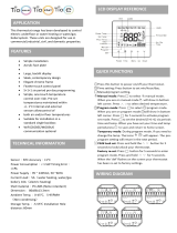
Standard Digital Touchpad Control
Keys and Indicators Labels
ON/OFF, FAN SPEED, MODE
7 Push Buttons FAN MODE, SLEEP
Temp buttons:
for
Temp UP and for Temp DOWN
9 LED Indicators SLEEP, COOL, COOL/DRY, FAN,
HEAT, HIGH, LOW, CYCLE, CONT.
LED 2 Digit Displays No Label
Display Function Legend
Tr = Room Temperature
hI = High Room Temperature
Lo = Low Room Temperature
LA = Low Ambient Lockout
rT = Remote Thermostat Control
tP = Touchpad Control
t = Time
Ts = Temperature Setpoint
Rf = Room Freeze Condition
CF = Coil Freeze Protection
F = Fahrenheit
C = Celsius
LC = Control Lockout Mode
Remote Thermostat Control
The Remote Thermostat can be any thermostat
that can interface with an electronic thermostat via
RCWYBG terminals. The Control Selection jumper
must be in T’STAT position. During a call the remote
thermostat will pass R back to the controller on a
respective terminal. The push buttons on the touchpad
become inactive in the remote thermostat mode.
However, the control pad LED display will indicate
the mode of operation, and the room temperature.
Note:
In terms of outputs, there are two types of thermostats:
relay contacts and solid state.
If you open the thermostat and don’t see relays then it
must be solid state.
Manufacturers of solid state output thermostats in-
clude loading resistors on their installation kits. They
are of 560 Ohm and 3W value. These resistors are
meant to load thermostat solid state outputs in order
for the output voltage to be either 0 or 24VAC, i.e. no
oating voltage. These resistors are connected from W,
Y, G to common (C), respectively.
You can wire any type of 24Vac thermostat straight
into the remote thermostat connector of PTAC control
boards, 667997101 and 667997201 (Basic and Pre-
mium models) and the control boards will recognize
the signals from them.
Figure 14. Standard Digital Touchpad Control
9- LED
Indicators
Figure 15. Standard Digital Control Indicators
LED
2-Digit Display
7- Push Buttons

IM 950-1 / Page 16 of 38
Controls
Standard Digital Touchpad Control
Indoor and Outdoor Fan Operation
The indoor fan can be set to operate on High
or Low speed with the Fan Speed Button on the
touchpad. It can also be set for Continuous or Cycle
operation on the touchpad. When set for Continuous,
the “CONT” LED will be on and the fan will run
continuously. When set for Cycle, the “CYCLE” LED
will be on and the fan will turn on at a call for heat or
cooling.
Fan Cycle Operation
On a call for Heating or Cooling, the indoor fan
and the heating source or the compressor will be
activated. When the call is satised and the heating
source or the compressor is deactivated, the indoor fan
will repeatedly run for 2 minutes on and the number
of minutes selected on the PC Board off, until the next
cut-in cycle. The number of cycles with timing as
described above is determined based on the OFF FAN
CYCLE jumper setting.
Remote T’Stat Mode
The unit can be jumper congured to take
commands from a Remote Thermostat. The Remote
Thermostat will call for Heat and Cool through the
electronic controller.
1.
The Remote T’stat will control through the board
the work of the compressor, indoor and outdoor
fans, the reversing valve, and the heater
2. System will run in Cool mode when Y signal is
high. In cool mode compressor (therefore
outdoor fan) shall turn on
3. Cold start feature (see Modes of Operation – Cold
Start), Cool dry mode (see Cold Dry Mode) and
Sleep feature (see Sleep Feature) are not available
in Remote T’stat cool mode
Operation
Memory Recall
The digital control shall start with the last settings
used prior to power down. These settings are saved in a
non-volatile memory. Factory set mode is OFF.
On/Off Triggering
Control can be turned On/Off via LUI, Remote
T’stat, or Sleep feature. The control will show the
temperature set point when the mode is Cool, Cool
Dry, or Heat. The display will be blank in Fan mode.
1. On/Off triggering with LUI
Control shall turn On or Of
f when the On/Off
button is pressed in LUI. Once turned on control
shall start on the last mode used before it was
turned Off.
2. On/Off triggering with the Remote T’stat
Control shall be turned On if it was Of
f from the
Remote T’stat when it is set up to be controlled by
a Remote T’stat. A call for heat or cool from the
Remote T’stat will be used to turn the control on.
Control remains on until manually turned Off.
3. On/Off triggering with the Sleep feature
Sleep feature works in combination with the
Timer
setting. Sleep time setting shall be user adjustable
from 1 to 15 hours via the Touchpad. The timer
will count down and when it reaches “0” it will
turn the control Off if control was previously On
and vice versa, if it was Off it will turn On after
time expires. As mentioned in
protections section
of this spec the Sleep operation is overridden by
room freeze protection.
Control Off
When the control is in the Off Mode, relay outputs
will be disabled with the exception of the indoor
fan (blower). It will stay on to meet the Hot Keep
specication. Indicator LED’s are all off.
Temperature Range
The maximum operating temperature range is
selectable via the Touchpad and is 60°F to 85°F with
the limits included. The Remote Thermostat selectable
operating range is 60°F to 90°F with limits included.
The range is set in the Set-up menu.

IM 950-1 / Page 17 of 38
System Select Operation Using Remote
Thermostat
System will run in Heat mode and engage certain
outputs based on the system selection (jumper) as
described below (see Standard Digital Control Board
Wiring Diagram on page 31).
AC/ELE
• If AC/ELE is selected then a signal on W
terminal will call for heating.
HP or HP/ELE
• If HP or HP/ELE is selected then signals on Y
and B terminals will call for heating.
NOTES:
1. Hot start and Sleep features are not available in
Remote T’stat heat mode.
2. Control’s operation is subject to its own protection
features when controlled by a Remote T’stat
3. Indoor fan mode and the speed will default to
“cycle” and “high” when unit is controlled by
Remote T’stat
4. The indoor fan is turned on when G signal is high.
When there is no signal on G terminal then the
indoor fan will be turned off.
Control Lockout Feature
The control is placed in a lockout mode of
operation when Mode button is held pressed for 10
seconds. Display will show “LC” to conrm Lockout
Mode has been entered. Once in this Lockout Mode
the control board will not take any commands at all. In
Lockout, unit will continue to operate with the same
settings just prior to Lockout Mode. This means the
touchpad will no longer be able to pass commands
to the control. User’s set point will normally be
displayed. Any button pushed will bring “LC” on
display for ve seconds.
To exit the Lockout Mode and return to normal
(regular) mode of operation, press the Mode button for
10 seconds. Display will show “nL” for ve seconds to
conrm normal mode has been resumed.
Controls
Standard Digital Touchpad Control
Modes of Operation
Cool Mode
In Cool Mode, the compressor will start if the
temperature at the space temperature sensor is 1°F
or higher than the set point. It will stop if the space
temperature sensor is 2°F or lower than the set point,
subject to timing requirements.
In the Cool Mode, the indoor fan will operate
according to the user settings for Fan Mode –
Continuous or Cycle and Speed.
Cold Start
Cold start is initiated when the control has not
called for cooling for more than two (2) hours or
during a power-on-reset. During cold start, the set
point is lowered by 4°F (Tset-4°F) if the differential
calls for cooling. The unit will operate in cold start
until the new set point is satised (+ or – 1°F) or until
the unit has run in cold start for at least 20 minutes.
After one or both conditions are met, the set point will
be reset to the user setting and the unit will run in the
regular cool mode.
The indoor fan will operate according to the user
settings for mode – Continuous or Cycle and Speed.
Cold start is not available with the Sleep feature.
Sleep Function
Sleep time is adjustable by the user from 1 to 15
hours in one (1) hour increments in a closed loop. The
sleep time is adjusted and set via the touchpad and by
pressing the Sleep Button repeatedly. On the touchpad,
the display will show the set time in numbers for ve
(5) seconds. Before the sleep time expires, the setting
can be adjusted above the number of hours passed by
pressing the Sleep Button. Pressing the On/Off Button
can terminate the Sleep Mode.
A changeover from Heat to Cool or another Mode
will reset the Sleep Timer.
The Sleep Function will be deactivated by pressing
the power-on-reset or any button (except sleep) on the
touchpad or the Remote Control.

IM 950-1 / Page 18 of 38
Compressor
Low Fan
t
On
Off
On
Off
30 secs.
30 secs.
8 mins.
4 mins.
t
Figure 16. Zone A
Compressor
Low Fan
12 mins.
On
Off
On
Off
*
t
t
*
= Zone Determination Time
Figure 17. Zone B
Figure 18. Zone C
Compressor
Low Fan
t
On
Off
On
Off
30 secs.
30 secs.
6 mins.
6 mins.
t
*
= Zone Determination Time
*
Figure 19. Zone D
Compressor
Fan
t
On
Off
On
Off
t
12 mins.
*
*
= Zone Determination Time
Cool Dry Mode
Select the Cool Dry Mode when the standard Cool
Mode does not provide sufcient dehumidication. In
Cool Dry Mode, the unit must run in Cool Mode for 12
minutes or until the temperature differential between
the room temperature and the set point is less than
2°F. This will also occur after a Cold Start or a Mode
change from Cool to Cool Dry. During this time the
fan will operate in the Mode and Speed selected.
Until one or both of the above conditions are met,
the control will determine which Dry Mode (Zone) is
initiated based on the temperature differential between
the room temperature (Tr) and the temperature set
point (Ts):
Note: Cool Dry is not available with Sleep Function.
Figure 16. if Tr - Ts > 4°F, operation will be in Zone A
Figure 17. if 2°F < Tr - Ts < 4°F, operation will be in
Zone B
Figure 18. if 0°F < Ts - Ts < 2°F, operation will be in
Zone C
Figure 19. if Ts - Tr > 5°F, operation will be in Zone D
The other temperature ranges are dead bands for zone
stability.

IM 950-1 / Page 19 of 38
Figure 20. Indoor Air and Indoor Coil Sensor
Locations
Indoor
Coil Sensor (ICS)
Indoor
Air Sensor (IAS)
Heat Mode
Unit will call for heating based on the type of
the heat source it has: heat pump in reverse cycle,
hydronic or electric.
1) Hot Start
Hot Start is possible when the control has not
called for heat in more than (2) hours or during power-
on-reset. During Hot Start, the user’s set point is raised
4°F (Ts + 4°F). The unit will only call for heat if room
temperature dif
ferential calls for heat.
The unit will continue in Hot Start Mode until the
new set point is satised (with a 1°F differential)
or unit has run for at least 20 minutes. After one or
both conditions are met, the set point will be reset
to the user’s setting and the unit will run in regular
heat mode. Hot start is not available with the Sleep
feature. The fan will operate per the Fan Mode and
Speed setting.
2) Hot Keep
In Hydronic Heat: When the water valve closes, the
indoor fan will operate per the user mode (Constant or
Cycle) and speed setting.
Heat Fan Lock Out Control: When the unit is in
the Heat Mode, but when hot water or steam is not
available, it prevents the indoor fan from operating.
The indoor fan will only operate in the “Fan Only” and
“Cool Modes”.
In Electric Heat: When the heater cuts out the indoor
fan will continue to run for 15 seconds at set speed
regardless of “On or Off” mode.
3) Sleep Function
Sleep time is user adjustable from 1 to 15 hours in
one hour increments in a closed loop via the touch
pad by pressing the Sleep button repeatedly. The
Sleep Mode can be terminated by pr
essing the
On/Off button.
The Sleep Function will lower the temperature
setting with time. Changing the Mode or a changeover
from Heat to Cool will reset the Sleep Timer.
The Sleep function will be deactivated by Power-
on-reset or by pressing any button on the Touchpad
except Sleep.
4) Fan Mode
In the Fan Mode, the fan will operate continuously
at the user’s speed setting. The compressor and
outdoor fan will not operate. In single motor units,
the outdoor fan will run along with the indoor fan.
Set Up Mode
To enter the Set Up Mode, simultaneously press the
Mode, Up and Down buttons for 5 seconds. To change
settings, press the Up or Down button. To move from
one screen to another, press the Mode button.
To exit Set Up, press the Mode, Up and Down
buttons simultaneously for 5 seconds or control will
automatically exit Set Up in 15 seconds.
Settings within the Set Up Mode are as follows:
1) Control Selection:
To view the Control Selection Screen, press and
hold the Up and Down buttons for 5 seconds. The
setting may be changed by pressing either the Up or
Down button. The “tP” setting is the default setting
and indicates the touchpad control.
2) Temperature Limit Settings
To advance from Control Selection to Temperature
Limit Settings, press the Mode button once. To set the
Cool Minimum set point, press and hold Fan Cycle
button and adjust the setting with the Up or Down
buttons. The minimum setting is 60°F.
To set the Heat Maximum set point, press and hold
Fan Speed button and adjust the setting with the Up or
Down buttons. Maximum setting is 85°F.
The Display will show the upper operating limits
rst. The default settings are Cool min. = 60°F and
Heat max. = 85°F.
3) Hydronic Valve Operation
To advance from Temperature Limit Settings to
Hydronic Valve operation, press the Mode button
once. To toggle the setting, press either the Up or
Down button. Settings are “no” (normally open) and
“nc” (normally closed). Default setting is “no.”
4) Indoor Air Sensor Reading
To advance from Hydronic Valve operation to
Indoor Air Sensor Reading, press the Mode Button
once. The control readout will show room temperature.
Modes of Operation-Description
Standard Digital Touchpad Control

IM 950-1 / Page 20 of 38
Outdoor Air Sensor Reading
To advance from Indoor Coil Sensor reading to
Outdoor Air Sensor reading, press the Mode button
once. The control readout will show the outdoor air
sensor temperature.
Thermistor Failure Code and Condition
The system treats a sensor open or short as
extremely cold or hot and reacts accordingly. The
exception is the room air sensor, in which case the
system will turn off. When the fault is corrected by
replacement or repair, the respective error code will
clear from the display (Table 1).
Compressor Random Restart
When power is interrupted, a random compressor restart
delay of 0 to 2 minutes is initiated. In the Cool Mode only,
the compressor will start operating only after the random
delay plus 2 minutes (minimum off time for thermostat,
ie. 2 to 4 minutes). Random delay is used only during
system startup or reset.
Unit Protective Logic
Compressor Minimum Run Time
For thermostat-controlled running cycles, the
compressor will have a minimum run time of 90
seconds. The compressor can be stopped at any time if
the system is switched to any Mode, except the Cool
Dry Mode.
Figure 21. Outdoor Air Sensor Location
Outdoor Air Sensor
(OAS)
Compressor Minimum Off Time (delay on
break)
When compressor is under the thermostat control,
it has a 3-minute delay before restarting when it has
cycled off.
Indoor Coil Freeze Protection
In Anti-Freeze Mode, the compressor and outdoor
fan will be stopped and the display will show “CF”.
The compressor and outdoor fan can be started only if
the following conditions are met:
1.
after the 3 minute delay on break, AND
2. the indoor coil reaches 49°F or above and remains
there for at least 1 minute, OR
3. another Mode is selected.
The system is in Anti-Freeze Mode when the
following conditions are met:
1.
The control is in either Cool or Cool/Dry Mode.
2. The indoor coil reaches 32°F and stays there for at
least ve (5) minutes.
3. The compressor has run for at least 90 seconds.
Sleep Timer is overridden during this operation.
Anti-freeze Protection is active in all modes of
operation and when the control is Off.
Room Freeze Protection
When room temperature falls below 41°F, the
hydronic valve is opened and the indoor fan operates
on High Speed. The compressor and outdoor fan are
off and the display will show “Rf”. The hydronic valve
will close when the room temperature rises back to
50°F. During room freeze conditions, the temperature
setting can be adjusted with the touchpad. Fan modes
and Sleep Operation are overridden during Room
Freeze Protection. Room Freeze Protection is active in
all modes of operation and when control is off.
Temperature Limiting
When the room temperature drops 5°F below set
point, the display will indicate “Lo.” When the room
temperature rises 5°F above set point, the display
will indicate “hI.” Alarm indications of 5°F above or
below set point will be consistent with the set up mode
settings for minimum and maximum temperatures.
Modes of Operation
Table 1. – Failure Code and Condition
Thermistor Sensor Condition Error Code
< - 58°F or
Room > 140°F or E1
Open or Close
< - 22°F for > 2s or
Indoor Coil > 176°F for > 2s or E2
Open or Close
< - 22°F for > 2s or
Outdoor Air > 176°F for > 2s or E4
Open or Close
/