Page is loading ...

IM 354 / Page 1
Bulletin No. IM 354-4
June 1995
Form No. 802048241
Installation and
Maintenance Data
®
MQT (Type RS)
Incremental
®
Heat Pump
©1995 McQuay International
Model Nomenclature
Product Family
MQT (previously Type RS)
Unit Size
06 = Nominal 6,000 Btuh cooling
09 = Nominal 9,000 Btuh cooling
11 = Nominal 11,000 Btuh cooling
14 = Nominal 14,000 Btuh cooling
Vintage Designation
B (Sizes 06, 09, 11)
C (Size 14)
Unit Type
A = Air conditioner with electric heat
B = Air conditioner with hydronic heat
C = Heat pump with supplemental electric heat
MQT 09 B C 5 B
Heater Code
A = 2.0 kW electric heat
B = 3.2 kW electric heat
C = 4.8 kW electric heat
G = Steam heat
W = Hot water heat
Voltage
3 = 230/60/1
5 = 208/60/1
7 = 265/60/1

Page 2 / IM 354
Installation and maintenance are to be performed only by qualified personnel who are familiar with local codes and
regulations, and experienced with this type of equipment. Caution: Sharp edges and coil surfaces are a potential
injury hazard.
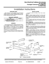
Conditioner Description
The McQuay MQT heat pump is designed and built for
through-the-wall installation in either new or existing build-
ings. The self-contained refrigerant system delivers cooling
or reverse cycle heating depending on which is called for and
has back-up electric resistance heating.
1. Subbase — Optional on 208 or 230 volt units; standard on
265 volt units. Shipped in a separate carton.
2. Louver Frame — Optional; shipped in separate carton.
3. Room Cabinet/Wall Sleeve — Shipped in palletized car-
ton with heating/cooling chassis.
4. Outdoor Louver — Shipped in separate carton.
5. Heating/Cooling Chassis — Shipped in palletized carton
with room cabinet/wall sleeve.
Figure 1.
20
3
⁄4"
(527mm)
Min. 9
3
⁄4"
(248mm)
Wall Line
44
7
⁄8"
(1140mm)
1
3
⁄8"
(35mm)
3
3
⁄4"
(95mm)
Filter
42
1
⁄2"
(1080mm)
1
3
⁄16"
(30mm)
5
1
⁄2"
(140mm)
4
3
⁄8" to 15
5
⁄8"
(111 to 397mm)
7
1
⁄4"
(184mm)
16
3
⁄8"
(416mm)
4"–4
1
⁄2"
(102 –114mm)
3
⁄8" (10mm) Louver-Stamped (Standard) or
1
1
⁄8" (29mm) Louver-Extruded (Optional)
3
⁄8" (10mm)
Louver-Stamped
(Standard) or
1
1
⁄8" (29mm)
Louver-Extruded
(Optional)
1
2
3
3
1
Note:
4" minimum space requirement between
underside of unit and floor for return air.
¿ Subbase is optional on 208 and 230
volt units but standard on 265 volt.
¡ A
3
⁄4" (19mm) drip lip.
¬ Optional condensate connection.
Figure 2. Conditioner — wall mounted
9
3
⁄4"
(248mm)
Min.
4" (102mm)
Min.
2" x 4" (51 x 102mm)
Junction Box
All wiring should be done in accordance with all local and
National Electrical Code requirements. The conditioners are
supplied as follows:
1. 208 or 230 Volt Models — Supplied with an attachment
cord and plug which exit from beneath the conditioner on
the right side through a grommeted hole. The cord has a
usable length of 48" (1220mm) from where it exits the
conditioner. The use of an extension cord to increase the
length of the plug/cord set is not recommended. The
attachment plug size should be used to determine the
Electrical Service
circuit ampacity and overcurrent protection. Time delay
fuses are recommended to avoid nuisance tripping. An
optional subbase is available and contains a junction box
for a field mounted receptacle. Suggested outlet loca-
tions are as follows:
a. Wall Mounted Conditioner — Generally mounted
beneath the conditioner on or recessed in the wall so
it is concealed by the conditioner overhang (see Figure
2). The space under the conditioner must be at least 4"
(102mm) high.

IM 354 / Page 3
b. Conditioner with Subbase — Where the optional
subbase is used, the rectangular knockout in the right
front bottom of the wall sleeve is removed to allow the
subbase junction box to be mounted directly beneath
the wall sleeve (see Figure 3).
2. 265 Volt Models — Permanently wired to the subbase
junction box receptacle. A short interconnecting cord is
furnished from the chassis to reach this receptacle to
preserve the ease of quick chassis changeout. The condi-
tioner is marked with the minimum circuit ampacity and
maximum fuse size. The subbase and receptacle are
standard factory supplied equipment on these models.
Incremental air conditioners can be installed in various ways.
This instruction is based on the use of an optional subbase,
an optional louver frame and an optional condensate drain.
The following is a recommended installation procedure:
Optional Condensate Drain
If it is used, provisions should be made in the stub-up area for
the condensate connection (see Figure 4). Since the MQT
Heat Pump has a reverse cycle heating feature, it generates
condensate during the heating season which may not be
completely removed by the normal condensate disposal
system. A condensate drain opening is therefore provided at
the left bottom front of the heating/cooling chassis; it is
shipped from the factory with a rubber plug inserted. An
optional condensate drain kit is available, and it is recom-
mended that it be used to connect the chassis to condensate
drain (by others). A knockout is provided in the basepan of
the wall sleeve for this purpose.
Optional Subbase
Whenever a subbase is used, it must be installed prior to the
room/cabinet wall sleeve.
The subbase, provided in four pieces, is adjustable from
4
3
⁄8" to 15
5
⁄8" (111 to 397mm) in depth to accommodate
various projections of the conditioner into the room. The
standard subbase height is 4" (102mm) with adjustable
leveling bolts to 4
1
⁄2" (114mm). In all cases, the subbase
provides a 5
1
⁄2" (140mm) toe space inset from the front edge
of the conditioner. Thus, for applications where the minimum
9
3
⁄4" (248mm) conditioner projection into the room is utilized,
only the 4
3
⁄8" (111mm) deep front section of the subbase is
required. The adjustable side extension pieces should be
discarded. The adjustable “L” shaped extension pieces are
used when the conditioner projection into the room is greater
that 9
3
⁄4" (248mm). The scoring at two-inch intervals on the
extension pieces can be broken at the desired depth. The
extensions are secured with two screws on each side to the
front section on the subbase. In all cases the back of the
subbase remains open and is butted against the wall (see
Figures 4 and 5).
Optional Subbase & Codensate Drain Installation
Figure 4.
Figure 3. Conditioner — with subbase
*Note: These are actual unit dimensions. The rough
opening through the wall should be at least
1
⁄4" (6mm)
larger without louver frame, or at least
5
⁄8" (16mm)
larger when louver frame is used.
Unit Outside
Dimensions
Optional Subbase
Optional Subbase Front
Access Cover
Opening for
Condensate Drain
Receptacle
Leveling Bolt
Screw
Receptacle
Cover
Centerline of Wall
Opening/Subbase
Screw
16
3
⁄
8
"
(416mm)*
Equipment
Ground Wire
Wall Opening
Electrical
Stub-up Area
44
7
⁄
8
" (1140mm)*

Page 4 / IM 354
C
L
5. Complete the electrical work in the subbase and the
junction box.
6. Rough-in the condensate drain (if used) to the left front
side of the subbase. A connection may be made between
this field supplied drain and the condensate drain which
will be installed later at the underside of the wall sleeve.
7. The subbase cavity should be fitted with a piece of 6"
(152mm) fiberglass batting to prevent condensation on
the wall sleeve basepan.
Subbase Installation:
1. The subbase provides a 1
3
⁄16" (30mm) inset on the sides of
the conditioner. Locate the subbase on the floor and align
its center line with the center line of the wall opening (see
Figure 5).
2. Determine the depth of the side extension pieces desired
and break at the proper score line. Insert the extension
pieces into the front assembly and secure with two short
screws on each side (see Figure 4).
3. Secure the assembly to the floor.
4. Insert the two leveling bolts into the subbase, one on each
end. Retain the two long screws to secure the wall sleeve
after it is installed.
Optional Louver Frame Installation
Whenever a louver frame is used, it must be installed prior to,
or at the same time as, the room cabinet/wall sleeve. It must
be level and square (see Figure 6).
1. Apply a bead of good caulking compound around the four
inner surfaces of the louver frame vertical flange (see
Figure 7).
2. Insert the sleeve of the louver frame into the wall opening
from the exterior of building and apply firm pressure so the
caulked louver frame vertical flanges are snug against the
exterior building surface.
3. Secure the louver frame to the wall through the sides and
top of the sleeve. Never secure the louver frame through
the bottom. Note: The louver frame may also be secured
from inside the room cabinet/wall sleeve by screws driven
through the sides and top of the louver frame sleeve.
Pre-Installation Conditioner Preparation
1. Remove the outer carton of the room cabinet/wall sleeve/
chassis package and inspect the conditioner for shipping
damage. Report any damage to the carrier.
2. Save the large inner cardboard liner which can be reused
to cover the installed conditioner until its ready for use. It
is scored, and can be easily folded to the proper depth for
the particular room cabinet exposure into the room.
Room Cabinet/Wall Sleeve Installation
Figure 5.
3. Remove the front panel and filter. Refer to page 7 for
details.
4. Remove the retaining clips at the bottom rear of the
chassis which hold the chassis in place during shipment.
5. Remove the chassis by pulling evenly at the positions
indicated as “Hand Holds” only. Caution: Do not pull on
the evaporator fan housings or control box.
6. Check the nameplate data on the chassis to ensure that
the correct jobsite distribution has been made with re-
spect to the heating and cooling capacities. Corner rooms
normally require larger capacities.
9
⁄16" (14mm)
Outline of Cabinet/Wall Sleeve
0" to 11
1
⁄4"
(0 to 286mm)
14
3
⁄8"
(365mm)
21
1
⁄4"
(540mm)
21
1
⁄4"
(540mm)
4
5
⁄8"
(117mm)
9
9
⁄16"
(243mm)
2
9
⁄16"
(65mm)
Electrical
Junction Box
4
3
⁄8" (111mm)
1
3
⁄16" (30mm)
Condensate Drain
Rough-in Area
2
1
⁄2"
(64mm)
5
⁄8" (16mm)
3" (76mm)
5"
(127mm)
5"
(127mm)
22
7
⁄8"
(581mm)
3
1
⁄2" (89mm)
5
1
⁄2" (140mm)
Electrical
Rough-in Areas
Top View
Figure 6.
*Outside dimensions
Louver Frame
18
5
⁄8"
(473mm)
16
5
⁄8"
(422mm)*
3
3
⁄8"
(86mm)
1
1
⁄16"
(2mm)
47
1
⁄8" (1197mm)
45
1
⁄4" (1150mm)*

IM 354 / Page 5
Panel and Thin Wall Application
1. Install the subbase as described in the subbase installa-
tion section.
2. Install the louver frame as described in the louver frame
installation section.
3. Position the room cabinet/wall sleeve in the louver frame
opening and on the subbase. The rear face of the cabinet
should be recessed from the outside edge of the louver
frame by the depth of the louver to be installed (Figure 7).
4. Remove the rectangular knockout in the base pan of the
wall sleeve.
5. Adjust the subbase leveling bolts so the room cabinet/
wall sleeve is level or tilted a maximum of
1
⁄8" (3mm)
downward to the outside. Secure the room cabinet/wall
sleeve to the subbase with the two long screws retained
from the subbase assembly (see Figure 4). Holes,
5
⁄32" in
diameter, have been added to each side of the room
cabinet/wall sleeve as a provision for securing the sleeve
in the wall opening. Each hole is located 2" (51mm) down
from the top and 2" (51mm) in from the rear of the sleeve.
These holes or other non-perforated locations in the sides
and/or top of the sleeve may be used to fasten the sleeve
to the wall from the inside. Never secure the room
cabinet/wall sleeve to the wall through the bottom.
6. Caulk the outdoor joint between the conditioner and wall
opening or louver frame around the top, bottom, and both
sides. Do not permit caulking to block weep holes.
Masonry and Thick Wall Application
Preparation of Wall Opening — In new construction, the
room cabinet/wall sleeve can be built into the building wall as
construction progresses, or openings can be left for later
installation. A lintel must be used to support any brick or
masonry work above the conditioner.
1. For installations with an optional subbase, install the
subbase as described in the subbase installation sec-
tion.
2. Set the room cabinet/wall sleeve in soft mortar and
position it in the wall opening. The rear face of the
conditioner should be recessed from the outside edge of
the wall opening by the depth of the louver to be installed
(see Figure 8). The center of gravity of the conditioner is
9
1
⁄2" (241mm) from the rear face. For wall mounted
conditioners, the center of gravity must be within the
load bearing portion of the wall; otherwise some method
of support is required.
3a. Installations without a subbase. Level or pitch the
room cabinet/wall sleeve a maximum of
1
⁄8" (3mm) down-
ward to the outside. Holes,
5
⁄32" in diameter, have been
added to each side of the room cabinet/wall sleeve as a
provision for securing the sleeve in the wall opening.
Each hole is located 2" (51mm) down from the top and
2" (51mm) in from the rear of the sleeve. These holes or
other non-perforated locations in the sides and/or top of
the sleeve may be used to fasten the sleeve to the wall
from the inside. Never secure the room cabinet/wall
sleeve to the wall through the bottom.
3b. Installations with an optional subbase. Adjust the
subbase leveling bolts such that the room cabinet/wall
sleeve is level or tilted a maximum of
1
⁄8" (3mm) down-
ward to the outside. Secure the room cabinet/wall sleeve
to the subbase with the two long screws retained from
the subbase assembly (see Figure 4). Holes,
5
⁄32" in
diameter, have been added to each side of the room
cabinet/wall sleeve as a provision for securing the sleeve
in the wall opening. Each hole is located 2" (51mm) down
from the top and 2" (51mm) in from the rear of the sleeve.
These holes or other non-perforated locations in the
sides and/or top of the sleeve may be used to fasten the
sleeve to the wall from the inside. Never secure the room
cabinet/wall sleeve to the wall through the bottom.
4. Caulk outdoor joint between conditioner and wall opening
around the top, bottom and both sides. Do not permit
caulking to block weep holes.
3
3
⁄8"
(86mm)
Leveling Bolt
4" (102mm)
Cabinet Sleeve
Finished
Wall
Louver
Depth
Louver
Frame
(Optional)
Outside
Wall
Secure Cabinet
Sleeve To
Subbase
Finished
Floor
5
⁄32" (4mm) Dia.
(Typical of 2)
Subbase
(Optional)
2"
(51mm)
2"
(51mm)
Figure 7.
Outside
Wall
Louver
Depth
Mortar Base
5
⁄32" (4mm) Dia.
(Typical of 2)
Subbase
(Optional)
Finished
Floor
4" (102mm)
Min. 9"
(229mm)
Finished Wall
Lintel By
Others
Figure 8.
2"
(51mm)
2"
(51mm)

Page 6 / IM 354
Louver Installation
pull it back to the wall sleeve rear face so that the louver studs
pass through the holes in the wall sleeve flanges. Securely
tighten the louver in place using the washers and nuts provided.
Install the outdoor louver from inside the room. Hold the louver
with a wire loop or other similar means. Push the louver out
through the rear opening of the room cabinet/wall sleeve and
Heating/Cooling Chassis Installation
Chassis Inspection & Installation Preparation
Check the chassis for damage. Remove and discard the
condenser fan shipping bracket (see Figure 9). Spin the fan
wheels manually to confirm free rotation. Check the refriger-
ant tubing to determine that there are no kinks, and that it
does not rub against other parts. Report any shipping dam-
age to the carrier immediately.
Check the interior of the installed room cabinet/wall box.
Clean out any dirt or debris that may have accumulated,
particularly abrasive materials that could scratch the painted
surfaces.
Optional Condensate Connection
If it has been decided to use the condensate drain, you will
need the optional kit containing one flexible drain connector
tube, one drain tube assembly and two #8 mounting screws.
1. Install the flexible tube on the chassis drain (see Figure 10).
2. Remove the front access cover of the subbase (see Figure
11).
3. Remove the knockout in the bottom left side of the wall
sleeve and mount the drain tube assembly with two
screws (see Figure 11). The assembly may be installed at
various 90 degree positions to fit job requirements.
4. Make the connection to the field supplied drain previously
installed under the subbase installation instructions. The
outlet of the drain tube assembly is
1
⁄2" nominal copper
tubing (
5
⁄8" O.D. actual). The easiest method of connection
would be with a short length of
5
⁄8" I.D. flexible PVC tubing
having a wall thickness of at least
1
⁄8" (3mm) to prevent
kinking or collapse, however, follow all local applicable
codes.
Heating/Cooling Chassis Installation
1. Slide the chassis into the room cabinet/wall sleeve until
firmly seated against the weather seals. Caution: Push
only on positions marked “Hand Holds” and/or sheet-
metal flanges. Caution: Do not push on the coil surface,
control box cover, or fan scroll (see Figure 13). Caution:
Make sure that tubing does not catch when inserting
chassis.
2. Plug the electrical cord into the receptacle. Excess cord
should be coiled neatly and stored in the conditioner.
3. If the optional condensate drain kit is used, install the
flexible tube between the chassis and wall sleeve conden-
sate drain by pressing the tube into the drain assembly
(see Figure 12). Caution: When removing the chassis,
remember first to lift the tube from the drain assembly.
4. Set the manual damper operator in open or closed posi-
tion as desired (see Figure 14).
5. Check the “Standby/Normal” switch located on the face
of the control box. For normal heat pump operation,
position the switch to “Normal.” Only the electric heater
will operate when switch is in “Standby’ position.
Residential and institutional cleaning compounds can
cause permanent damage to the packaged terminal unit.
To avoid damage to unit controls and heat transfer sur-
faces, do not spray cleaning compounds onto the dis-
charge grille, the return air opening or the unit controls.
Normal cleaning can be accomplished by wiping the unit
surface with a damp cloth. When using cleaning com-
pounds on carpets, floor or walls, turn the unit off to avoid
drawing potentially damaging vapors into the package
terminal unit.
Figure 12.
Figure 9.
Figure 11.
Figure 10.
Knockout

IM 354 / Page 7
Filter Access/Front Panel Operation
Figure 15. Figure 16.
Figure 13. Figure 14.
1. The filter assembly must be removed before removing the
front panel. The filter assembly may be removed by
grasping the lower black decorative rail and pulling out.
The filter is contained in this assembly and may be
removed for cleaning.
2. To remove the front panel, remove the two sheetmetal
screws adjacent to the release buttons in the top ends of
the black border area.
3. Release the top of the panel by depressing the two vertical
buttons in the top of the black border. When the condi-
tioner is new, some inward pressure on the buttons may
be required to effect release.
4. Tilt the panel out from the room cabinet and lift up to
disengage the hinging tabs in the lower corners from the
cabinet.
5. To install the front panel, insert the hinging tabs into the
slots in the bottom of the cabinet. Push the top of the front
panel closed, exerting sufficient pressure on the top black
border area to allow the latching buttons to snap into
place, usually with an audible click.
6. Replace the two sheetmetal screws adjacent to the latch-
ing buttons in the front panel.
7. Replace the filter assembly at the bottom of the front
panel.
Initial start-up of the Incremental conditioners by an experi-
enced technician is usually the responsibility of the installing
contractor. This consists of inspecting and operating the
equipment for all functions at time of initial installation, and
making necessary adjustments. It also includes demonstrat-
ing its proper operation to the owner or his agent. Note that
unless otherwise specifically agreed to in writing, McQuay
includes no field labor, start-up service or the like in the price
of its equipment. After the equipment leaves the factory, it
may become damaged or maladjusted during transportation
or on the job. Sometimes wires are disconnected acciden-
tally, or fan motors move on their bases due to rough
handling, causing fans to strike. The correction of such
conditions is part of the start-up.
Equipment Start-up

Before Starting Equipment Make Certain That:
1. The correct voltage has been supplied to the equipment.
2. The electrical plug from the control box has been inserted
into the receptacle.
During Start-up (Applies only to standard equipment)
1. Set the ventilation damper to the OPEN or CLOSED
position as required by the owner.
2. Push the HIGH button to select the fan speed; push the
HEAT button. Move the thermostat control to the extreme
heating position (counterclockwise). Heat should cycle on
and off as the thermostat requires. Push the LOW button;
the fan should change to the lower speed.
One-Year Warranty of Entire Conditioner— McQuay Inter-
national, hereinafter referred to as the “Company,” warrants
to the original owner that the entire Incremental Comfort
Conditioner is free from defects in material and workman-
ship. Any part or portion thereof which becomes defective
under normal use during the period of this warranty will be
repaired or replaced provided the Company’s examination
shall prove to its satisfaction that the part was or became
defective under normal use. This warranty contemplates that
first year maintenance labor was arranged for with the
installer or otherwise at the time the conditioner was pur-
chased or installed. The Company’s obligations under this
warranty are limited to: (a) Repairing the defective part or (b)
Furnishing a replacement part provided the defective part is
returned to the factory, transportation charges prepaid. No
reimbursement will be made for expenses incurred in making
field adjustments or replacements unless specifically autho-
rized in writing by the Company.
This warranty constitutes the buyer’s sole remedy. It
is given in lieu of all other warranties. There is no implied
warranty of merchantability or fitness for a particular
purpose. In no event and under no circumstance shall the
Company be liable for incidental or consequential dam-
ages, whether the theory be breach of this or any other
warranty, negligence, or strict tort.
No person (including any agent, salesman, dealer or
distributor) has authority to expand the Company’s obliga-
tion beyond the terms of this express warranty, or to state
that the performance of the product is other than that
published by the Company.
One Year Refrigeration Circuit Warranty — Hermetically
sealed motor-compressor assemblies and all components
of refrigeration circuits not readily separable therefrom are
warranted to the original owner for one year. Refrigerating
circuits consist of the motor-compressor assembly evapora-
tor coil, condenser coil and interconnecting tubing. Repairs
under this warranty will be made at the Company’s expense
provided that the refrigerating circuit is delivered without
shipping damage, transportation prepaid to the factory or to
a factory designated repair station, at the Company’s option.
This one-year warranty does not include any other parts of
the equipment such as filters, fans, fan motors, controls,
cabinet parts, electrical relays, capacitors, protective de-
vices, or wiring. The Company is not obligated under this
warranty for field labor such as service for inspection, remov-
ing, packing and/or reinstalling the refrigeration circuit, nor
for return transportation charges.
General Conditions — The above warranties are void if the
Company’s equipment has been damaged, misused, sub-
jected to abnormal use or service or its serial number has
been altered, defaced or removed, or payment for the equip-
ment is in default. The Company is not responsible for
service to correct conditions due to misapplication, im-
proper installation, inadequate wiring, incorrect voltage con-
ditions or unauthorized opening of the refrigeration circuit,
nor for consequential damages. In case the Company’s
equipment is installed in conjunction with cabinets, grilles,
louvers, controls or other parts manufactured by others,
these warranties shall apply only to the Company manufac-
tured portion of the equipment. The conditions of the war-
ranty plan are effective for eighteen (18) months from date of
factory shipment. The Company reserves the right to make
a handling and inspection charge in the case of parts or
equipment improperly returned as defective and/or as being
in warranty.
3. Push the HIGH button to select the fan speed; push the
COOL button. Move the thermostat control to the extreme
cooling position (clockwise). The compressor should cycle
on and off as the thermostat requires. Push the LOW
button; the fan should change to the lower speed.
4. Push the OFF or STBY button. The fan should stop and
neither the heater nor the compressor should continue to
operate.
Note: The direction of the conditioned air may be adjusted by
rotation of discharge grilles to change airflow pattern in a
room. The building superintendent or manager should be
requested to make any changes, as a thin flat-edged tool is
required to move grille.
Installation, Service & Warranty Policy
Printed on recycled paper containing at least 10% post-consumer recycled material.
13600 Industrial Park Blvd., P.O. Box 1551, Minneapolis, MN 55440 USA (612) 553-5330
/