Barco BarcoGraphics 8200 LC User manual
- Category
- Projectors
- Type
- User manual
This manual is also suitable for
Page is loading ...

Due to constant research, the information in this manual is subject
to change without notice.
Produced by BARCO NV, April 1997.
All rights reserved.
Trademarks are the rights of their respective owners.
Printed in Belgium
Due to constant research, the information in this manual is subject
to change without notice.
Produced by BARCO NV, April 1997.
All rights reserved.
Trademarks are the rights of their respective owners.
Printed in Belgium

Table of Contents
5975288 BARCOGRAPHICS 8200 110497
i-1
Table of Contents
5975288 BARCOGRAPHICS 8200 110497
i-1
WARNINGS & SAFETY INSTRUCTIONS ....................................................................................................................................... 1-1
AVERTISSEMENTS & PRESCRIPTIONS DE SECURITE .............................................................................................................. 1-1
UNPACKING & DIMENSIONS ........................................................................................................................................................ 2-1
Unpacking............................................................................................................................................................................ 2-2
Projector dimensions............................................................................................................................................................ 2-3
Battery installation in the RCU.............................................................................................................................................. 2-4
INSTALLATION GUIDELINES ........................................................................................................................................................ 3-1
Installation guidelines .......................................................................................................................................................... 3-2
* Environment ...................................................................................................................................................................... 3-2
* What about ambient light ? ................................................................................................................................................ 3-2
* Which screen type? ........................................................................................................................................................... 3-3
* What image size? How big should the image be?............................................................................................................. 3-3
* Where to install the projector? ........................................................................................................................................... 3-4
* How to install a projection lens? ........................................................................................................................................ 3-6
INSTALLATION SET UP ................................................................................................................................................................. 4-1
LOCATION AND FUNCTION OF CONTROLS ................................................................................................................................ 5-1
Front panel terminology ....................................................................................................................................................... 5-2
Control Panel Terminology ................................................................................................................................................... 5-3
POWER CONNECTION .................................................................................................................................................................. 6-1
Power cord connection......................................................................................................................................................... 6-2
Fuses................................................................................................................................................................................... 6-2
Switching on ........................................................................................................................................................................ 6-3
Switching to stand-by ........................................................................................................................................................... 6-4
Switching off ........................................................................................................................................................................ 6-4
INPUT MODULE CONNECTIONS .................................................................................................................................................. 7-1
Input connections. ................................................................................................................................................................ 7-2
Input module insertion into the projector ............................................................................................................................... 7-2
Video/S-video input module ................................................................................................................................................. 7-3

Table of Contents
i-2
5975288 BARCOGRAPHICS 8200 110497
Table of Contents
i-2
5975288 BARCOGRAPHICS 8200 110497
RGB analog input module. ................................................................................................................................................... 7-6
Component input module. .................................................................................................................................................... 7-9
RGB3S/RG3sB input module. .............................................................................................................................................7-11
Connecting a computer, e.g. IBM PC (or compatible), Apple Macintosh to the RS 232 input of the projector. ......................7-13
Set up of the baud rate for communication with a computer................................................................................................7-13
Connecting a RCVDS 05 to the projector. ...........................................................................................................................7-14
Connecting a VS05 to the projector. ....................................................................................................................................7-14
Connecting an IR Remote Receiver 800 to the projector. ....................................................................................................7-14
CONTROLLING .............................................................................................................................................................................. 8-1
How to use the RCU? .......................................................................................................................................................... 8-2
Projector address ................................................................................................................................................................. 8-3
How to display a projector address?..................................................................................................................................... 8-4
How to program an address into the RCU? .......................................................................................................................... 8-4
Picture controls with direct access. ...................................................................................................................................... 8-4
START UP OF THE ADJUSTMENT MODE..................................................................................................................................... 9-1
Adjustment Mode ................................................................................................................................................................. 9-2
GUIDED ADJUSTMENT MODE .................................................................................................................................................... 10-1
RANDOM ACCESS ADJUSTMENT MODE .................................................................................................................................. 11-1
Starting up the Random Access Adjustment Mode ............................................................................................................ 11-2
File service ........................................................................................................................................................................ 11-3
Load file ............................................................................................................................................................................. 11-4
Edit file............................................................................................................................................................................... 11-5
Rename ............................................................................................................................................................................. 11-9
Copy ................................................................................................................................................................................ 11-10
Delete .............................................................................................................................................................................. 11-11
File Options ..................................................................................................................................................................... 11-12
Picture Tuning ................................................................................................................................................................. 11-12
Sync slow/fast.................................................................................................................................................................. 11-13
Still Video......................................................................................................................................................................... 11-13
Color Balance .................................................................................................................................................................. 11-14
RGB analog input module. ................................................................................................................................................... 7-6
Component input module. .................................................................................................................................................... 7-9
RGB3S/RG3sB input module. .............................................................................................................................................7-11
Connecting a computer, e.g. IBM PC (or compatible), Apple Macintosh to the RS 232 input of the projector. ......................7-13
Set up of the baud rate for communication with a computer................................................................................................7-13
Connecting a RCVDS 800 or RCVDS 05 to the projector. ...................................................................................................7-14
Connecting a VS05 to the projector. ....................................................................................................................................7-14
Connecting an IR Remote Receiver 800 to the projector. ....................................................................................................7-14
CONTROLLING .............................................................................................................................................................................. 8-1
How to use the RCU? .......................................................................................................................................................... 8-2
Projector address ................................................................................................................................................................. 8-3
How to display a projector address?..................................................................................................................................... 8-4
How to program an address into the RCU? .......................................................................................................................... 8-4
Picture controls with direct access. ...................................................................................................................................... 8-4
START UP OF THE ADJUSTMENT MODE..................................................................................................................................... 9-1
Adjustment Mode ................................................................................................................................................................. 9-2
GUIDED ADJUSTMENT MODE .................................................................................................................................................... 10-1
RANDOM ACCESS ADJUSTMENT MODE .................................................................................................................................. 11-1
Starting up the Random Access Adjustment Mode ............................................................................................................ 11-2
File service ........................................................................................................................................................................ 11-3
Load file ............................................................................................................................................................................. 11-4
Edit file............................................................................................................................................................................... 11-5
Rename ............................................................................................................................................................................. 11-9
Copy ................................................................................................................................................................................ 11-10
Delete .............................................................................................................................................................................. 11-11
File Options ..................................................................................................................................................................... 11-12
Picture Tuning ................................................................................................................................................................. 11-12
Sync slow/fast.................................................................................................................................................................. 11-13
Still Video......................................................................................................................................................................... 11-13
Color Balance .................................................................................................................................................................. 11-14

Table of Contents
5975288 BARCOGRAPHICS 8200 110497
i-3
Table of Contents
5975288 BARCOGRAPHICS 8200 110497
i-3
Gamma............................................................................................................................................................................ 11-15
Geometry ......................................................................................................................................................................... 11-16
Shift ................................................................................................................................................................................. 11-16
Size ................................................................................................................................................................................. 11-17
Side keystone .................................................................................................................................................................. 11-18
Blanking........................................................................................................................................................................... 11-19
Options ............................................................................................................................................................................ 11-21
INSTALLATION............................................................................................................................................................................. 12-1
Starting up the Installation Mode ........................................................................................................................................ 12-2
Input Slots.......................................................................................................................................................................... 12-3
Convergence ..................................................................................................................................................................... 12-4
Configuration ..................................................................................................................................................................... 12-9
Internal Patterns ................................................................................................................................................................ 12-9
Configuration ..................................................................................................................................................................... 12-9
SERVICE MODE........................................................................................................................................................................... 13-1
Starting up the Service Mode ............................................................................................................................................. 13-2
Identification ...................................................................................................................................................................... 13-5
Change Password ............................................................................................................................................................. 13-7
How to enable or disable the password function ? ............................................................................................................. 13-7
How to change the password ? .......................................................................................................................................... 13-9
Change Language ............................................................................................................................................................. 13-9
Change Projector Address ............................................................................................................................................... 13-10
Change Baudrate PC....................................................................................................................................................... 13-10
Reset Lamp Runtime ....................................................................................................................................................... 13-11
Lamp Run Time History ................................................................................................................................................... 13-12
Panel Adjustments ........................................................................................................................................................... 13-13
Preset Input Balance ....................................................................................................................................................... 13-14
60 Hz Tracking ................................................................................................................................................................ 13-15
I2C diagnosis. .................................................................................................................................................................. 13-16
OPTIONAL EQUIPMENT .............................................................................................................................................................. 14-1
IR Receiver 800 ................................................................................................................................................................. 14-2

Table of Contents
i-4
5975288 BARCOGRAPHICS 8200 110497
Table of Contents
i-4
5975288 BARCOGRAPHICS 8200 110497
Hardwired RCU. ..................................................................................................................................................................14-2
RCVDS 05 ..........................................................................................................................................................................14-3
VS05...................................................................................................................................................................................14-3
MAGIK Interface .................................................................................................................................................................14-4
Adapter and communication cables.....................................................................................................................................14-4
Ceiling Mount Kit CM100.....................................................................................................................................................14-5
Projector Transport Handle .................................................................................................................................................14-6
Projector Frame for Dual or Triple Configurations ................................................................................................................14-6
Multifunctional flight case ....................................................................................................................................................14-7
Mechanical Shutter .............................................................................................................................................................14-8
Adjustable lensholder ..........................................................................................................................................................14-8
Appendix A : Standard source set up files. ...................................................................................................................................... A-1
Appendix B : Battery replacement in the RCU. ................................................................................................................................ B-1
Appendix C : Focusing the lens .......................................................................................................................................................C-1
Appendix D : Lens Cleaning Procedure ........................................................................................................................................... D-1
Appendix E : Source numbers 90 - 99 ............................................................................................................................................. E-1
Appendix F : Lenses........................................................................................................................................................................ F-1

Safety Instructions
5975288 BARCOGRAPHICS 8200 110497
1-1
Safety Instructions
5975288 BARCOGRAPHICS 8200 110497
1-1
WARNINGS
AVERTISSEMENTS
Safety instructions
Prescriptions de securite
On safety
Securite
On installation
Installation
On servicing
Entretien et reparation
On cleaning
Nettoyage
On repacking
R
e-emballage
On illumination
E
clairage
WARNINGS
AVERTISSEMENTS
Safety instructions
Prescriptions de securite
On safety
Securite
On installation
Installation
On servicing
Entretien et reparation
On cleaning
Nettoyage
On repacking
R
e-emballage
On illumination
E
clairage
Page is loading ...

Safety Instructions
5975288 BARCOGRAPHICS 8200 110497
1-3
Safety Instructions
5975288 BARCOGRAPHICS 8200 110497
1-3
Notice on safety
Projectors are built in accordance with the requirements of the
international safety standards IEC950, UL 1950 and CSA C22.2 No.
950, which are the safety standards of information technology equip-
ment including electrical business equipment.
These safety standards impose important requirements on the use of
safety critical components, materials and isolation, in order to protect
the user or operator against the risk of electric shock and energy
hazard, and having access to live parts.
Safety standards also impose to the internal and external temperature
rises, radiation levels, mechanical stability and strength, enclosure
construction and protection against risk of fire.
Simulated single fault condition testing ensures the safety of the
equipment to the user even when the equipment's normal operation
fails.
Installation instructions
Before operating your projector please read this manual thoroughly,
and retain it for future reference.
Installation and preliminary adjustments should be performed by
qualified BARCO personnel or authorized BARCO service dealers.
OWNER’S RECORD
The part number and serial number are located at the rear of the
projector. Record these numbers in the spaces provided below. Refer
to them whenever you call upon your BARCO dealer regarding this
product.
PART NUMBER:
SER. NUMBER:
DEALER:
Page is loading ...

Safety Instructions
5975288 BARCOGRAPHICS 8200 110497
1-5
Safety Instructions
5975288 BARCOGRAPHICS 8200 110497
1-5
The lightning flash with an arrowhead within a
triangle is intended to tell the user that parts
inside this product are risk of electrical shock
to persons.
The exclamation point within a triangle is in-
tended to tell the user that important operating
and/or servicing instructions are included in the
technical documentation for this equipment.
Warning
To prevent fire or electrical shock hazard, do not expose this projector to rain or moisture
Federal communication commission (FCC statement)
This equipment has been tested and found to comply with the limits
for a class A digital device, pursuant to Part 15 of the FCC Rules.
These limits are designed to provide reasonable protection against
harmful interference when the equipment is operated in a commercial
environment. This equipment generates, uses, and can radiate radio
frequency energy and, if not installed and used in accordance with the
instruction manual, may cause harmful interference to radio commu-
nications. Operation of this equipment in a residential area is likely
to cause harmful interference in which case the user will be required
to correct the interference at his own expense.
Page is loading ...

Safety Instructions
5975288 BARCOGRAPHICS 8200 110497
1-7
Safety Instructions
5975288 BARCOGRAPHICS 8200 110497
1-7
Instructions to the user :
if this equipment does cause interference to radio or television
reception, the user may try to correct the interference by one or more
of the following measures :
- Re-orientation of the receiving antenna for the radio or television.
- Relocate the equipment with respect to the receiver.
- Plug the equipment into a different outlet so that the equipment and
receiver are on different branch circuits.
• Fasten cables connectors to the equipment by mounting screws.
Note :
The use of shielded cables is required to comply within the limits of
Part15 of FCC rules.
General safety instructions.
* All the safety and operating instructions should be read before using
this unit.
* The operating instructions manual should be retained for future
reference.
* All warnings on the projector and in the documentation manuals
should be adhered to.
* All instructions for operating and use of this equipment must be
followed precisely.
ON SAFETY
* This product should be operated from an AC power source. This
projector may be connected to an IT-power system.
* This product is equipped with a 3-wire grounding plug, a plug having
a third (grounding) pin. This plug will only fit into a grounding-type
power outlet. This is a safety feature. If you are unable to insert the
plug into the outlet, contact your electrician to replace your
obsolete outlet. Do not defeat the purpose of the grounding-type
plug.
WARNING FOR THE CUSTOMERS
: THIS APPARATUS MUST BE
GROUNDED (EARTHED) via the supplied 3 conductor AC power
cable.
(If the supplied power cable is not the correct one, consult your
dealer.)
A. Mains lead (AC Power cord) with CEE 7 plug:
The colors of the mains lead are colored in
accordance with the following code:
Green-and-yellow: Earth (safety earth)
Blue: Neutral
Brown: Live
B. Power cord with ANSI 73.11 plug:
The wires of the power cord are colored in
accordance with the following code.
Green/yellow: ground
White: neutral
Black: live
* Do not allow anything to rest on the power cord. Do not locate this
product where persons will walk on the cord.
Page is loading ...

Safety Instructions
5975288 BARCOGRAPHICS 8200 110497
1-9
Safety Instructions
5975288 BARCOGRAPHICS 8200 110497
1-9
* To disconnect the cord, pull it out by the plug. Never pull the cord
itself.
* If an extension cord is used with this product, make sure that the
total of the ampere ratings on the products plugged into the
extension cord does not exceed the extension cord ampere rating.
Also make sure that the total of all products plugged into the wall
outlet does not exceed 15 amperes.
* Never push objects of any kind into this product through cabinet
slots as they may touch dangerous voltage points or short out parts
that could result in a risk of fire or electrical shock.
* Never spill liquid of any kind on the product. Should any liquid or
solid object fall into the cabinet, unplug the set and have it checked
by qualified service personnel before resuming operations.
* Lightning - For added protection for this video product during a
lightning storm, or when it is left unattended and unused for long
periods of time, unplug it from the wall outlet. This will prevent
damage to the projector due to lightning and AC power-line surges.
* To reduce the lamp heat of the projector, switch the projector
first
to stand-by and let the projector lamp cool down for at least 15
minutes. Then the projector may be switchedoff with the power
switch.
On Installation
* Do not place this projector on an unstable cart, stand, or table. The
projector may fall, causing serious damage to it.
* Do not use this projector near water.
* Use only the power cord supplied with your projector. While
appearing to be similar, other power cords have not been safety
tested at the factory and may not be used to power the projector.
For a replacement power cord, contact your dealer.
* Slots and openings in the cabinet and the sides are provided for
ventilation; to ensure reliable operation of the projector and to
protect it from overheating, these openings must not be blocked or
covered. The openings should never be blocked by placing the
product on a bed, sofa, rug, or other similar surface. This prod-
uct should never be placed near or over a radiator or heat register.
This projector should not be placed in a built-in installation or
enclosure unless proper ventilation is provided.
Surface
Air circulation
Build-in Dust filter
Page is loading ...

Safety Instructions
5975288 BARCOGRAPHICS 8200 110497
1-11
Safety Instructions
5975288 BARCOGRAPHICS 8200 110497
1-11
* Do not block the projector cooling fans or free air movement under
and around the projector. Loose papers or other objects may not be
nearer to the projector than 4" on any side.
On Servicing
Do not attempt to service this projector yourself, as opening or
removing covers may expose you to dangerous voltage potential and
risk of electric shock! Refer all projector service to a qualified BARCO
service center.
Call for service in the following conditions :
- When the power cord or plug is damaged or frayed.
- If liquid has been spilled into the projector.
- If the product has been exposed to rain or water.
- If the product does not operate normally when the operating
instructions are followed.
Adjust only those controls that are covered by the operating in-
structions since improper adjustment of the other controls may
result in damage and will often require extensive work by a qualified
technician to restore the product to normal operation;
- If the product has been dropped or the cabinet has been damaged;
- If the product exhibits a distinct change in performance, indicating
a need for service.
Replacement parts
- When replacement parts are required, be sure
the service technician has used original BARCO replacement parts
or authorized replacement parts which have the same characteris-
tics as the BARCO original part. Unauthorized substitutions may
result in degraded performance and reliability, fire, electric shock or
other hazards. Unauthorized substitutions may void warranty.
Safety check
- Upon completion of any service or repairs to this
projector, ask the service technician to perform safety checks to
determine that the projector is in proper operating condition.
The projecor uses a metal halide projection lamp. Replacing the
projection lamp with any other projection lamp can cause overheat-
ing or unacceptable image quality. Use only the projection lamps
specified by BARCO, or an authorized BARCO dealer or service
center.
On Cleaning
Unplug this product from the wall outlet before cleaning. Do not use
liquid cleaners or aerosol cleaners. Use a damp cloth for cleaning.
To keep the cabinet looking brand-new, periodically clean it with a soft
cloth. Stubborn stains may be removed with a cloth lightly dampened
with mild detergent solution. Never use strong solvents, such as
thinner or benzine, or abrasive cleaners, since these will damage the
cabinet.
* Do not block the projector cooling fans or free air movement under
and around the projector. Loose papers or other objects may not be
nearer to the projector than 4" on any side.
On Servicing
Do not attempt to service this projector yourself, as opening or
removing covers may expose you to dangerous voltage potential and
risk of electric shock! Refer all projector service to a qualified BARCO
service center.
Call for service in the following conditions :
- When the power cord or plug is damaged or frayed.
- If liquid has been spilled into the projector.
- If the product has been exposed to rain or water.
- If the product does not operate normally when the operating
instructions are followed.
Adjust only those controls that are covered by the operating in-
structions since improper adjustment of the other controls may
result in damage and will often require extensive work by a qualified
technician to restore the product to normal operation;
- If the product has been dropped or the cabinet has been damaged;
- If the product exhibits a distinct change in performance, indicating
a need for service.
Replacement parts
- When replacement parts are required, be sure
the service technician has used original BARCO replacement parts
or authorized replacement parts which have the same characteris-
tics as the BARCO original part. Unauthorized substitutions may
result in degraded performance and reliability, fire, electric shock or
other hazards. Unauthorized substitutions may void warranty.
Safety check
- Upon completion of any service or repairs to this
projector, ask the service technician to perform safety checks to
determine that the projector is in proper operating condition.
The projecor uses metal halide projection lamp. Replacing the
projection lamp with any other projection lamp can cause overheat-
ing or unacceptable image quality. Use only the projection lamps
specified by BARCO, or an authorized BARCO dealer or service
center.
On Cleaning
Unplug this product from the wall outlet before cleaning. Do not use
liquid cleaners or aerosol cleaners. Use a damp cloth for cleaning.
To keep the cabinet looking brand-new, periodically clean it with a soft
cloth. Stubborn stains may be removed with a cloth lightly dampened
with mild detergent solution. Never use strong solvents, such as
thinner or benzine, or abrasive cleaners, since these will damage the
cabinet.
Page is loading ...

Safety Instructions
5975288 BARCOGRAPHICS 8200 110497
1-13
Safety Instructions
5975288 BARCOGRAPHICS 8200 110497
1-13
To ensure the highest optical performance and resolution, the
projection lenses are specially treated with an anti-reflective coating,
therefore : avoid touching the lens. To remove dust on the lens, use
a soft dry cloth. Do not use a damp cloth, detergent solution, or thinner.
Follow the lens cleaning procedure on Appendix D in the Owners
Manual.
On Repacking
Save the original shipping carton and packing material; they will come
in handy if you ever have to ship your projector. For maximum
protection, repack your set as it was originally packed at the factory.
On illumination
In order to obtain the best quality for the projected image, it is essential
that the ambient light which is allowed to fall on the screen be kept to
an absolute minimum.
When installing the projector and screen, care must be taken to avoid
exposure to ambient light directly on the screen. Avoid adverse
illumination on the screen from direct sunlight or fluorescent lighting
fixtures.
The use of controlled ambient lighting, such as incandescent spot
light or a dimmer, is recommended for proper room illumination.
Where possible, care should also be taken to ensure that the floors
and walls of the room in which the projector is to be installed are non-
reflecting, dark surfaces. Brighter surfaces will tend to reflect and
diffuse the ambient light and hence reduce the contrast of the
projected image on the screen.
Page is loading ...

Unpacking & Dimensions
2-2
5975646 BARCOGRAPHICS 8100 090296
Unpacking & Dimensions
2-2
5975646 BARCOGRAPHICS 8100 090296
Unpacking
To open the banding, pull on the clip as shown in the first drawing.
Take the projector out of its shipping carton and place it on a table.
For transportation, the projector is mounted on a wooden board with 3 bolts. Use a 13 mm wrench to remove these bolts.
When using the projector as a table mounted configuration, always mount the 3 supporting feet (see drawing below). These feet are
mounted on the same wooden board. Each food contains one metal part and two plastic parts. To remove the feed, first turn out both plastic
parts. To remove the metal parts from the board, remove the retaining bolts. Save these bolts because these bolts must be used to mount
the feet to the projector. Mount first the metal parts with the removed bolts and turn in then both plastic parts to finish the assembly
Warning : To prevent overheating of the projector as table mounted, always remove the wooden board and turn in the 3 supporting feet
to allow air circulation via the built-in dust filter at the bottom.
1
234
5
379
Save the original shipping carton and packing material, they will
come in handy if you ever have to ship your projector. For maximum
protection, repack your projector as it was originally packed at the
factory.
Contents of the shipped box :
- 1 BARCOGRAPHICS 8100
- 1 remote control unit RCU + 9V battery
- 1 power cable with outlet plug type CEE7 or ANSI 73.11.
- 1 owner’s manual
- 3 supporting feet
Pull
To open

Unpacking & Dimensions
5975646 BARCOGRAPHICS 8100 090296
Unpacking & Dimensions
5975646 BARCOGRAPHICS 8100 090296
2-3
2-3
Name lens L min L max
(*) mm(inch) mm(inch)
HD(1.2:1) 1072 (42.20) 1087 (42.79)
HD(2.2:1) 1043 (41.06) 1070 (42.12)
HD(3.3:1) 1017 (40.04) 1072 (42.20)
HD(3.9:1) 1022 (40.24) 1162 (45.75)
HD(5:1) 1082 (42.60) 1202 (47.32)
HD(7:1) 1252 (49.29) 1372 (54.02)
HD(1.5-3:1) 1325 (52.17) 1355 (53.35)
(*) More info about lenses, see appendix F
Some examples of lenses :
Projector dimensions
(units : mm)
L

Unpacking & Dimensions
2-4
5975646 BARCOGRAPHICS 8100 090296
Unpacking & Dimensions
2-4
5975646 BARCOGRAPHICS 8100 090296
Battery installation in the RCU.
A battery (not yet installed to save the battery life time) is delivered inside the plastic bag with the power
cord. To install the battery, remove the battery cover on the backside of the remote control by pushing
the indicated handle a little to the bottom of the RCU. Lift up the top side of the cover at the same time
(fig. 1).
Insert the new 9 V battery (type E-block or equivalent) in the lower compartment and connect the battery
to the contact plate.
Insert the battery into the lower compartment and put the cover back.
Note : projector address has to be programmed on the RCU before using the RCU (see chapter
'Controlling').
fig.1
310a.DRW
fig.2
Insert here the 'Insert card
RCU' which you can cut out
on the last page of this
manual.
Contact
plate
Battery

Installation Guidelines
5975288 BARCOGRAPHICS 8200 110497
3-1
Installation Guidelines
3-1
5975288 BARCOGRAPHICS 8200 110497
INSTALLATION GUIDELINES
Environment
What about ambient light?
Which screen type?
What image size? How big should the image be?
Where to install the projector?
How to install the projector?
INSTALLATION GUIDELINES
Environment
What about ambient light?
Which screen type?
What image size? How big should the image be?
Where to install the projector?
How to install the projector?

Installation Guidelines
3-2
5975288 BARCOGRAPHICS 8200 110497
Installation Guidelines
5975288 BARCOGRAPHICS 8200 1104973-2
Installation guidelines
Careful consideration of things as image size, ambient light level, projector placement and type of screen to use are critical to the optimum
use of the projection system.
Max. ambient temperature : 40°C.
* Environment
Do not install the projection system in a site near heat sources such
as radiators or air ducts, or in a place subject to direct sunlight,
excessive dust or humidity. Be aware that room heat rises to the
ceiling; check that temperature near the installation site is not
excessive.
* What about ambient light ?
The ambient light level of any room is made up of direct or indirect
sunlight and the light fixtures in the room. The amount of ambient light
will determine how bright the image will appear. So, avoid direct light
on the screen.
Windows that face the screen should be covered by opaque drapery
while the set is being viewed. It is desirable to install the projecting
system in a room whose walls and floor are of non-reflecting material.
The use of recessed ceiling lights and a method of dimming those
lights to an acceptable level is also important. Too much ambient light
results in a ‘wash out’ of the projected image. That appears as less
contrast between the darkest and lightest parts of the image. With
bigger screens, the ‘wash out’ becomes more important. As a general
rule, darken the room to the point where there is just sufficient light to
read or write comfortably. Spot lighting is desirable for illuminating
small areas so that interference with the screen is minimal.
Installation guidelines
Careful consideration of things as image size, ambient light level, projector placement and type of screen to use are critical to the optimum
use of the projection system.
* Environment
Do not install the projection system in a site near heat sources such
as radiators or air ducts, or in a place subject to direct sunlight,
excessive dust or humidity. Be aware that room heat rises to the
ceiling; check that temperature near the installation site is not
excessive.
* What about ambient light ?
The ambient light level of any room is made up of direct or indirect
sunlight and the light fixtures in the room. The amount of ambient light
will determine how bright the image will appear. So, avoid direct light
on the screen.
Windows that face the screen should be covered by opaque drapery
while the set is being viewed. It is desirable to install the projecting
system in a room whose walls and floor are of non-reflecting material.
The use of recessed ceiling lights and a method of dimming those
lights to an acceptable level is also important. Too much ambient light
results in a ‘wash out’ of the projected image. That appears as less
contrast between the darkest and lightest parts of the image. With
bigger screens, the ‘wash out’ becomes more important. As a general
rule, darken the room to the point where there is just sufficient light to
read or write comfortably. Spot lighting is desirable for illuminating
small areas so that interference with the screen is minimal.

Installation Guidelines
5975288 BARCOGRAPHICS 8200 110497
3-3
Installation Guidelines
3-3
5975288 BARCOGRAPHICS 8200 110497
* Which screen type?
There are two major categories of screens used for projection
equipment. Those used for front projected images and those for rear
projection applications.
Screens are rated by how much light they reflect (or transmit in the
case of rear projection systems) given a determined amount of light
projected toward them. The ‘GAIN’ of a screen is the term used. Front
and rear screens are both rated in terms of gain. The gain of screens
range from a white matte screen with a gain of 1 (x1) to a brushed
aluminized screen with a gain of 10 (x10) or more. The choice
between higher and lower gain screens is largely a matter of personal
preference and another consideration called the Viewing angle.
In considering the type of screen to choose, determine where the
viewers will be located and go for the highest gain screen possible. A
high gain screen will provide a brighter picture but reduce the viewing
angle.
For more information about screens, contact your local screen
supplier.
* What image size? How big should the image be?
The BARCOGRAPHICS 8200 is designed for projecting an image
size (video) from 1.00m (3.3ft) to 15.00m (49.2ft) with a aspect ratio
of 4 to 3.
Screen width

Installation Guidelines
3-4
5975288 BARCOGRAPHICS 8200 110497
Installation Guidelines
5975288 BARCOGRAPHICS 8200 1104973-4
* Where to install the projector?
Definitions of the Abbreviation on drawings
B = Distance between ceiling and top of the screen or between
floor and bottom of the screen.
A = Correction value, distance between bottom side of projec-
tor and middle of the lens. Value to be subtracted from B to
obtain the correct installation position. (A value is a constant
value for all screen widths and type of lenses, A = 195 mm.)
CD = Total distance between projector and ceiling or projector
and floor.
SW = Screen width.
SH = Screen height (image height).
PD = Projector Distance, distance between screen and projec-
tor.
Inputs and computer video format input compatibility :
Some examples :
VIDEO and S-VIDEO
COMPONENT VIDEO
RGB ANALOG with STANDARD SYNC (SYNC ON GREEN or
SEPARATE SYNC)
RGB ANALOG with TRI-LEVEL SYNC (SYNC ON GREEN or
SEPARATE SYNC)
VGA : 640 x 480 pixels
MAC : 640 x 480 pixels
Super VGA : 800 x 600 pixels
XGA : 1024 x 768 pixels
up to 1280 x 1024 pixels
Sources with pixel clock < 135 MHz
Lens type selection.
a) determine the required screen width.
b) determine the approximate position of the projector in the projection
room with regard to the screen and measure the
projector-screen distance (PD).
c) refer to the lens diagrams to find the best corresponding PD
with regard to the measured projector-screen distance for the
required screen width.
The lens type is determined (lens name is indicated on top of the
page).
Start the installation procedure for the projector as described in
the manual.

Installation Guidelines
5975288 BARCOGRAPHICS 8200 110497
3-5
Installation Guidelines
3-5
5975288 BARCOGRAPHICS 8200 110497
Table mounting of the BARCOGRAPHICS 8200Ceiling mounting of the BARCOGRAPHICS 8200
Screen
PD
B
Ceiling
Projector
CD
A
CD = B - A
SH
Optical axis projection lens
SH
SW
SIDE VIEW
BACK VIEW
Screen
BOTTOM VIEW
SW
Ceiling
Screen
PD
B
Floor
Projector
CD
A
CD = B - A
SH
Optical axis projection lens
SH
SW
SIDE VIEW
BACK VIEW
Screen
TOP VIEW
SW
Floor
Page is loading ...
Page is loading ...
Page is loading ...
Page is loading ...
Page is loading ...
Page is loading ...
Page is loading ...
Page is loading ...
Page is loading ...
Page is loading ...
Page is loading ...
Page is loading ...
Page is loading ...
Page is loading ...
Page is loading ...
Page is loading ...
Page is loading ...
Page is loading ...
Page is loading ...
Page is loading ...
Page is loading ...
Page is loading ...
Page is loading ...
Page is loading ...
Page is loading ...
Page is loading ...
Page is loading ...
Page is loading ...
Page is loading ...
Page is loading ...
Page is loading ...
Page is loading ...
Page is loading ...
Page is loading ...
Page is loading ...
Page is loading ...
Page is loading ...
Page is loading ...
Page is loading ...
Page is loading ...
Page is loading ...
Page is loading ...
Page is loading ...
Page is loading ...
Page is loading ...
Page is loading ...
Page is loading ...
Page is loading ...
Page is loading ...
Page is loading ...
Page is loading ...
Page is loading ...
Page is loading ...
Page is loading ...
Page is loading ...
Page is loading ...
Page is loading ...
Page is loading ...
Page is loading ...
Page is loading ...
Page is loading ...
Page is loading ...
Page is loading ...
Page is loading ...
Page is loading ...
Page is loading ...
Page is loading ...
Page is loading ...
Page is loading ...
Page is loading ...
Page is loading ...
Page is loading ...
Page is loading ...
Page is loading ...
Page is loading ...
Page is loading ...
Page is loading ...
Page is loading ...
Page is loading ...
Page is loading ...
Page is loading ...
Page is loading ...
Page is loading ...
Page is loading ...
Page is loading ...
Page is loading ...
Page is loading ...
Page is loading ...
Page is loading ...
Page is loading ...
Page is loading ...
Page is loading ...
Page is loading ...
Page is loading ...
Page is loading ...
Page is loading ...
Page is loading ...
Page is loading ...
Page is loading ...
Page is loading ...
Page is loading ...
Page is loading ...
Page is loading ...
-
 1
1
-
 2
2
-
 3
3
-
 4
4
-
 5
5
-
 6
6
-
 7
7
-
 8
8
-
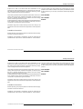 9
9
-
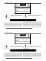 10
10
-
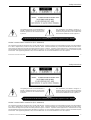 11
11
-
 12
12
-
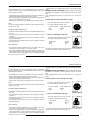 13
13
-
 14
14
-
 15
15
-
 16
16
-
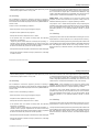 17
17
-
 18
18
-
 19
19
-
 20
20
-
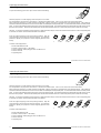 21
21
-
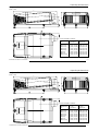 22
22
-
 23
23
-
 24
24
-
 25
25
-
 26
26
-
 27
27
-
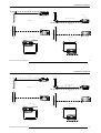 28
28
-
 29
29
-
 30
30
-
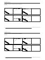 31
31
-
 32
32
-
 33
33
-
 34
34
-
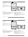 35
35
-
 36
36
-
 37
37
-
 38
38
-
 39
39
-
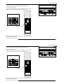 40
40
-
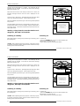 41
41
-
 42
42
-
 43
43
-
 44
44
-
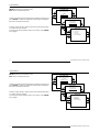 45
45
-
 46
46
-
 47
47
-
 48
48
-
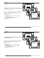 49
49
-
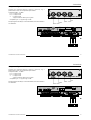 50
50
-
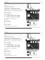 51
51
-
 52
52
-
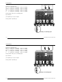 53
53
-
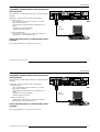 54
54
-
 55
55
-
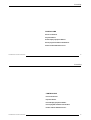 56
56
-
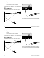 57
57
-
 58
58
-
 59
59
-
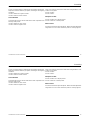 60
60
-
 61
61
-
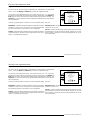 62
62
-
 63
63
-
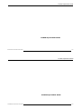 64
64
-
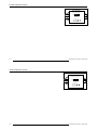 65
65
-
 66
66
-
 67
67
-
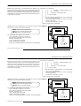 68
68
-
 69
69
-
 70
70
-
 71
71
-
 72
72
-
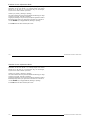 73
73
-
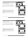 74
74
-
 75
75
-
 76
76
-
 77
77
-
 78
78
-
 79
79
-
 80
80
-
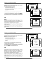 81
81
-
 82
82
-
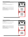 83
83
-
 84
84
-
 85
85
-
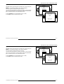 86
86
-
 87
87
-
 88
88
-
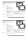 89
89
-
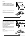 90
90
-
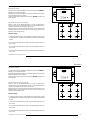 91
91
-
 92
92
-
 93
93
-
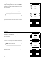 94
94
-
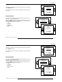 95
95
-
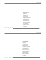 96
96
-
 97
97
-
 98
98
-
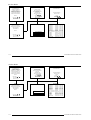 99
99
-
 100
100
-
 101
101
-
 102
102
-
 103
103
-
 104
104
-
 105
105
-
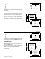 106
106
-
 107
107
-
 108
108
-
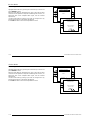 109
109
-
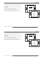 110
110
-
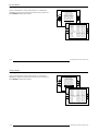 111
111
-
 112
112
-
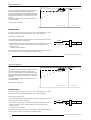 113
113
-
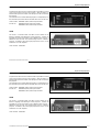 114
114
-
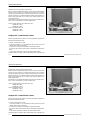 115
115
-
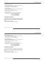 116
116
-
 117
117
-
 118
118
-
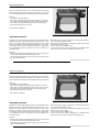 119
119
-
 120
120
-
 121
121
-
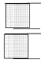 122
122
-
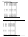 123
123
-
 124
124
-
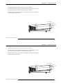 125
125
-
 126
126
-
 127
127
-
 128
128
-
 129
129
-
 130
130
-
 131
131


Barco BarcoGraphics 8200 LC User manual
- Category
- Projectors
- Type
- User manual
- This manual is also suitable for
Ask a question and I''ll find the answer in the document
Finding information in a document is now easier with AI
Related papers
-
Barco OverView mDR50-DL Owner's manual
-
-
-
Barco DP-2000 Installation guide
-
-
-
-
Barco OverView cDG67-DL Owner's manual
-
Barco iCon H600 lamp kit (300W UHP) Installation guide
-
Other documents
-
Minka Group P5544-66A-L User manual
-
Mitsubishi Electric PROJ-EST Datasheet
-
Runco CRT Television DTV-940/943 User manual
-
NEC GT1150 User manual
-
 Videk 9252L Datasheet
-
NEC SX10000 Owner's manual
-
Black Box AC400A User manual
-
Solutions MS-C01 Installation guide
-
Zenith Model PRO900X User manual
-
