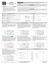
Simpson Electric Hawk H340 User manual
- Category
- Wall clocks
- Type
- User manual
This manual is also suitable for

24
SIMPSON ELECTRIC COMPANY 520 Simpson Avenue
Lac du Flambeau, WI 54538-0099 (715) 588-3311 FAX (715) 588-3326
Printed in U.S.A. Part No. 06-117489 Edition 5, 06/07
Visit us on the web at: www.simpsonelectric.com
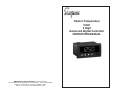
Hawk 3-Temperature
H340
4 Digit
Advanced Digital Controller
OPERATORS MANUAL

2
About this Manual
To the best of our knowledge and at the time written, the information contained
in this document is technically correct and the procedures accurate and ad-
equate to operate this instrument in compliance with its original advertised
specifications.
Notes and Safety Information
This Operator’s Manual contains warning symbols which alert the user to check
for hazardous conditions. These appear throughout this manual where appli-
cable, and are defined below. To ensure the safety of operating performance of
this instrument, these instructions must be adhered to.
!
Warning, refer to accompanying documents.
Caution, risk of electric shock.
This instrument is designed to prevent accidental shock to the operator when
properly used. However, no engineering design can render safe an instrument
which is used carelessly. Therefore, this manual must be read carefully and
completely before making any measurements. Failure to follow directions can
result in a serious or fatal accident.
Technical Assistance
SIMPSON ELECTRIC COMPANY offers assistance Monday through Friday
8:00 am to 4:30 pm Central Time. To receive assistance contact Technical
Support or Customer Service at (715) 588-3311.
Internet: http://www.simpsonelectric.com
Warranty and Returns
SIMPSON ELECTRIC COMPANY warrants each instrument and other articles
manufactured by it to be free from defects in material and workmanship under
normal use and service, its obligation under this warranty being limited to making
good at its factory or other article of equipment which shall within one (1) year
after delivery of such instrument or other article of equipment to the original
purchaser be returned intact to it, or to one of its authorized service centers,
with transportation charges prepaid, and which its examination shall disclose
to its satisfaction to have been thus defective; this warranty being expressly in
lieu of all other warranties expressed or implied and of all other obligations or
liabilities on its part, and SIMPSON ELECTRIC COMPANY neither assumes
nor authorizes any other persons to assume for it any other liability in connec-
tion with the sales of its products.
This warranty shall not apply to any instrument or other article of equipment
which shall have been repaired or altered outside the SIMPSON ELECTRIC
COMPANY factory or authorized service centers, nor which has been subject
to misuse, negligence or accident, incorrect wiring by others, or installation or
use not in accord with instructions furnished by the manufacturer.
!
23
NOTES:

3
NOTES
22
NOTES:

4
Contents
1. INTRODUCTION .............................................................................. 5
1.1 General Description .............................................................................. 5
1.2. Specifications ........................................................................................ 5
2. DISPLAY AND KEYPAD CONTROLS ............................................... 6
3. INSTALLATION AND PANEL CUTOUT ............................................. 6
3.1 Mounting Requirements ....................................................................... 6
3.2 Engineering Label Placement .............................................................. 7
4. REMOVING / INSTALLING OPTION MODULES .............................. 7
5. OPERATING THE KEYS ................................................................... 8
5.1 In Run Mode ......................................................................................... 8
5.2 In Program Mode .................................................................................. 8
5.3 In Edit Mode .......................................................................................... 8
6. PROGRAMMING MENU................................................................... 9
6.1 Relay Control ........................................................................................ 9
6.2 Display Control ................................................................................... 10
6.3 Measurement Control ......................................................................... 10
6.4 Output Control (If Present) .................................................................. 11
6.5 System Control ................................................................................... 11
6.6 Password ............................................................................................ 12
7. TEMPERATURE INPUT CARDS .................................................... 13
7.1 Relay Cards ........................................................................................ 13
7.2 Frequently Asked Questions ............................................................... 14
7.3 Power Supply Card ............................................................................. 14
8. MENU FLOWCHART ...................................................................... 16
9. MENU DETAIL ................................................................................ 18
9.1 Relay Control (Sp1-Sp4) ..................................................................... 18
9.1.1 Response .............................................................................................. 18
9.1.2 Delay ..................................................................................................... 18
9.1.3 Latch ..................................................................................................... 19
9.1.4 Alarm ..................................................................................................... 19
9.2 Display Control ................................................................................... 19
9.3 Output Control .................................................................................... 20
21
20mA) When the display reaches 0 percent the analog output would be 4mA.
The limits can be moved or reversed (HI=0 and LO= 80.0), in this case when
the display reads 0 , the analog output would be 20mA and when the display
reads 80, the analog output would be 4mA.
The Fail Safe option (FS) controls the action of the analog output when the
display goes into over-range (EEEE or –EEEE). In some cases, the low limit
or high limit are reserved for error conditions. With set to ‘HI’, the output will
run to the 20mA value when over-range or under-range occur. With failsafe set
to ‘LO’, the output will run to 4mA at over-range or under-range. With failsafe
‘Off’, the output will go to the defined limit ends. (-EEEE would be 4mA and
EEEE would be 20mA typically.)

5
1. INTRODUCTION
1.1 General Description
The Simpson Electric Hawk 3 Advanced Digital Panel Meter/Controller has 4-
digit display. All LEDs are 7 segment and offer 5 brightness levels. The high
quality instrument has user programmable parameters that are all set from the
front panel in easy to understand terminology. The display also shows acti-
vated set point indicators (up to four). The keypad buttons have audible and
tactile feedback to prevent keystroke errors.
1.2. Specifications
Specifications
Display:
Type: 7-segment, red LED
Quantity: 4
Height: 0.56” (14.2mm)
Decimal Point: None
Non Programmable
Brightness: 5 settings
User Programmable
Over-range: Display Reads EEEE Indicating Maximum Value
Under-range: Display Reads -EEEE Indicating Minimum Value
Alarm Indicators 4 LED indicators For up to 4 Independent Setpoints
Sensor Break: Display reads EEEE
(Burnout)
Power Requirements:
AC Voltages: 85 to 250 VAC/120 VAC @ 7W
DC Voltages: 9 to 36V DC @ 10W
Accuracy: All measurements are at 25° C and measured as
percent of reading.
Noise Rejection
NMRR: 60dB @ 50/60 Hz
CMRR: 100 db @ 50/60 Hz
A to D Conversion
Technique: Successive Approximation with oversampling
Sample Rate: 10 Conversions per second
Display Rate: User Programmable from 1/minute - 8/second
epyTtinUycaruccAegnaRerutarepmeT
001TPDTRtnuoC2-/+.%2.002- ⬚ 002+otC ⬚C
JtnuoC2-/+.%2.001- ⬚ 067+otC ⬚C
KtnuoC2-/+.%2
.002- ⬚ 0521+otC ⬚C
EtnuoC2-/+.%2.001- ⬚ 008+otC ⬚C
TtnuoC2-/+.%2.002- ⬚ 004+otC ⬚C
Environmental
Operating Temperature. 0 to 50°C
Storage Temperature. -10 to 60°C
Relative Humidity: <85%
Ambient Temperature: 25°C
Temperature Drift: ⫾100 ppm/C°⫾0.05dgt/⬚C
Warm up Time: 10 minutes
20
9.3 Output Control
An optional analog outputs is available.
The analog output is a current or voltage that represents an equivalent range
of signal on the input. Analog output can be purchased as 4-20mA DC out or
0-10V DC out. When installed, the Hawk 3 will sense the card and the menu
will open the choices available to it.
Setting the limits (LIM). The ends of the analog output range (4 & 20 or 0 & 10)
can be set or ‘pegged’ to and display value within the range of the meter.
Example: The Hawk 3 is purchased as a standard 200 volt meter. The analog
output is configured, by default, for HI=100.0 and LO=0.
When the display reaches 100 volts, the analog output would be 20mA. When
the display reaches 0 volts the analog output would be 4mA.
The Hawk3 is purchased as a process meter 4 – 20 mA input which will dis-
play 0-100 percent. The analog output is configured, by default, for HI=100.0
and LO=0. This means when the display reached 100 percent the analog out-
put would be 20 mA. (Also, because this is a process meter the input should be
The display banding, band, works from a different approach. The value en-
tered is the amount of digit movement allowed before the display should be
updated. With a band setting of 2, the value must move 2 counts up or down in
the rightmost position as compared to the current display to cause the display
to update.
NOTE: The two previous features can finely or coarsely stabilize the display
and remove the pops and jitters typically found when monitoring a power line.
The adjustment of this setting only filters what is displayed. The actual raw
signal is evaluated against the setpoint and will go into alarm even if the
display were set for maximum filtering and gave no indication of nearing the
setpoint. Use hysteresis on delay in SP menu to slow relay action.
The Brit( Brightness) of the display is adjustable to allow for dimming in low
light applications or for intensity matching with other equipment. The default is
set to the brightest setting (5).
ICE (Zero or Null) Using ICE allows the user to grab a running offset and zero
to it. A running offset can be useful for monitoring the tolerance to a value
instead of the value, cancelling lead error in measurement or removing some
signal difference in a measurement. Once ICE in enabled in the menu (ICE =
ON), the device will wait until the user presses S and T . At that point, the unit
will grab the current value and offset the display to zero. By choosing “hold” in
the ICE menu the ICE value can then be saved to a more permanent location.
No new ICE can be be taken, but the value will noy be lost if power fails.
NOTE: Be aware that introducing a ICE value will change the setpoint thresh-
olds and erase any previous Hi Lo readings.
HILO (Min/Max) allows the user track the history of the readings on the dis-
play. By pressing S, the unit will momentarily display the highest value it has
reached after last being reset. By pressing T, the unit will momentarily display
the lowest value it has reached after last being reset.

6
3.56
90.7mm
3.93"
99.8mm
2.04"
51.8mm
0.52"
13.2mm
3.24"
82.3mm
1.76"
44.7mm
1.77"
45mm
3.62"
92mm
Engineering Label
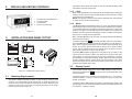
Figure 4-1. Installation and Panel Cutout
1. Activated set point indicators (4)
2. 4-button Keypad
3. Units Window
4. Numeric and message
Figure 2-1
2. DISPLAY AND KEYPAD CONTROLS
3.1 Mounting Requirements
The Hawk 3 Advanced Digital Controller 1/8 DIN counters require a panel
cutout of 1.77” (45mm) high be 3.62” (92mm) wide. To install the counter into
the panel cutout, remove the clips from the side of the meter. Slide the meter
through the panel cutout, then slide the mounting clips back on the meter.
Press evenly to ensure a proper fit.
3. INSTALLATION AND PANEL CUTOUT
19
seconds the alarm will trip and remain in alarm until the display drops below
the setpoint for at least 2.5 seconds
9.1.3 Latch
When choosing Ltch, the relay output will latch immediately after crossing the
setpoint. The unit can then only be unlatched with a front panel reset or a reset
command from the RS-485 port.
NOTE: If the display is still beyond the setpoint threshold, the reset will have
no effect and the unit will remain latched.
9.1.4 Alarm
The Alr mode allows choice between High, Low, or Off. The High Alarm means
that the display value must be greater or equal to the setpoint to go into Alarm.
The Low Alarm means that the display value must be less than or equal to the
setpoint to into alarm The Off Alarm means that all features of this setpoint is
disabled. No action will occur when display crosses a setpoint and the relays
will revert to a normally de-energized state.
When selecting St (State) from the menu, the display will alternate between
Stand the current setting.
To edit the setting press RE . Otherwise press T to move to the next choice.
If choosing ND (Normally De-energized) the relay will turn “on” the alarm con-
dition. This is a typical configuration. The one and two-relay outputs will act as
abeled; the normally closed contact will be closed until an alarm condition
occurs, and the opposite is true for the normally open connection. The four-
relay output only has the choice of normally open.
If choosing NE (Normally Energized) the relay will turn on at power up and
remain on until in an alarm condition. This mode can be used to create a fail-
safe condition or reverse the action of the four-relay configuration. In the fail-
safe example, the relay output would be wired to protect some device during
an alarm condition. During a power failure, the relay would be in the same
position as though it were in alarm thus protecting a device that may be on a
separate and possible active circuit.
9.2 Display Control
The next item that will appear in the menu is Dctl (Display Control). If this is
the item to be edited press
Enter
, otherwise press the down arrow T to move
to the next choice.
The display degrees, Deg, will allow you to select either °F or °C for the tem-
perature indication. There is no need to change this value if you prefer the
default °C indication.
The display refresh, frsh, will slow the numbers of updates to the display. This
setting ranges from as fast as 480 updates per minute (8 updates per second)
to as slow as 1 update per minute.
RESET
ENTER
RESET
ENTER

7
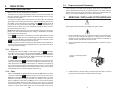
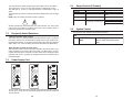
4.
REMOVING / INSTALLING OPTION MODULES
Shut off power before removing or installing any option module.
1. Remove module from case by inserting a screwdriver into tab slot open-
ing at top of input module (see Figure 5-1). Apply pressure to release
module from case. Repeat procedure for tab located on underside of
module and then slide module away from case.
2. Refer to appropriate sections to configure switches or jumpers for proper
operation.
!
3. Install module by carefully aligning module edges with slots in case and
pressing forward until tabs (on top and bottom) engage.
Figure 5-1. Removing Option
Module
3.2 Engineering Label Placement
If the engineering unit label needs replacing, place the tip of a ballpoint pen
into the small hole at the base of the engineering label in the bezel. Slide the
label up until it pops out. Grasp and remove. Slide the new label half the dis-
tance in, then use the ballpoint pen to slide it down into place.
18
Press RE to choose Val-1 as the setting to be edited. Notice that the far right
digit has an alternating cursor. To change this digit, use S or T. To move to the
next digit, press W. When all changes to the value are complete, press
RE to confirm the change and save it to memory.
NOTE: Any power loss before confirming a change will lose the edited value.
The menu will revert back to alternating between Val-1 and value. Press T to
move to the response setting.
9.1.1 Response
The display will now show “Rsp.” To edit response, press RE , otherwise
press T to move to the next choice. When editing Rsp., the display will show
Hyst, Dlay, or Ltch Flashing. Use S or T to choose the required response.
Press RE to confirm the choice. When choosing Hyst, the display will
alternate between Hyst and the current value.
To edit the value, press RE . Otherwise press T to move to the next choice.
Hysteresis will be used above and below the setpoint in equal amounts. The
value represents a percentage of the setpoint. For example: If the setpoint is
set to 100.00 with a high alarm and therhysteresis is set for 8.5%, the alarm
will not turn on until the reading on the display reaches 108.50. Once tripped,
the alarm will not turn off until the display reaches 91.50.
9.1.2 Delay
When choosing Dlay, the display will alternate between Dlay and current value.
To edit the value press RE . Otherwise press q to move to the next choice.
Dlay will be used above and below the setpoint in equal amounts. The value
represents the amount of delay in seconds. For example, if the setpoint is
again configured for high alarm and Dlay is set for 2.5 seconds the display
crosses the setpoint value and a timer begins to count off the 2.5 seconds
before the alarm trips. If, during those 2.5 seconds the value falls below the
setpoint, no action will be taken. When the unit successfully counts off 2.5
RESET
ENTER
RESET
ENTER
RESET
ENTER
RESET
ENTER
RESET
ENTER
RESET
ENTER
9. MENU DETAIL
9.1 Relay Control (Sp1-Sp4)
While in menu, all other operations are suspended.
The H340 has four setpoint parameters and up to four relays associated with
those four setpoints. The setpoint LEDs on the display will light even if no relay
is present for that setpoint.
To change the setpoint value, enter the menu by pressing W. If the password
allows relay control, it will be the first menu to appear. The display will show the
word “Sp1”. If this is the setpoint to be edited, press RE , otherwise press T
to move to the next choice. When editing Sp1, the display will alternate be-
tween Val-1 and a value. The “value” represents a threshold above or below
the setpoint being set to alarm.
NOTE: Before editing this value, be sure that the decimal point is in the proper
position. It is also recommended that any scaling or linearization be entered
before setpoints are determined.
RESET
ENTER

8
5. OPERATING THE KEYS
5.1 In Run Mode
W = Enters the Program Menu
S = Displays the Maximum Value (if enabled). Press S and hold while pressing
E to clear max. value.
T= Displays Minimum Value, if enabled. PressTand hold while pressing to
clear min. value
RESET/E = Resets Latched Relays (If any)
S and T = Sets Zero/ICE Value (if enabled). Also clears Minimum and Maxi-
mum Values
5.2 In Program Mode
W = Enters the Edit Mode. Flashing cursor shows value to edit. (Numeric Val-
ues only)
S = Scrolls “UP” through menu choices
T = Scrolls “DOWN” through menu choices
RE = Selects a menu or submenu to edit.
5.3 In Edit Mode
W = Moves Edit Cursor to the left. Flashing cursor shows value to edit (Nu-
meric Values Only)
S = Increases Numeric Value or Scrolls “UP” through sub-menu choices.
T = Decreases Numeric Value or Scrolls “DOWN” through sub-menu choices.
RE = Confirms and Saves your new setting.
IMPORTANT: After editing parameters, exit programming menu completely. If
this step is not followed, changes will not be saved.
RESET
ENTER
RESET
ENTER
RESET
ENTER
RESET
ENTER
RESET
ENTER
17
Page
2
Meas
ICE
ZERO
HILO
On
Off
On
Off
OCTL
Anlg
Value
Frd
Brd
Off
Dir
SpAn
FS
Value
Full
rEAd
HI
LO
SCTL
FACt
rSEt
PASS
Entr
Pwrd
Cng
Pwrd
rst
Pwrd

9
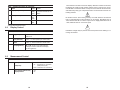
6. PROGRAMMING MENU
Depending on the operator’s password rights, some choices shown below be
unavailable. Use caution when changing values “on the fly” because relay
changes are immediate upon exiting menus. While in local menu, RS-485
communications will halt to avoid command conflict. While in local or remote
menu, relay and alarm operation are suspended. The local or remote menu
will “time out” in two minutes and resume normal operation.
6.1 Relay Control
)tneserpfi(1#yaleR&1#tnioPteS1PS
1-laV
eulaV*00001
)1esnopseR(1psR
tsyH
*yalD
hctL
%9.92ot*0
)*01.0(sdnoceS00.
06ot*0
evitcA
)1mralA(1-rlA
*IH
OL
FFO
)mralAnitonnehwetatS(1-tS
*DN
EN
EN
dezigrene-eD
rodezigrenE
dezigrene-eD
)
tneserpfi(2#yaleR&2#tnioPteS2PS
2-laV
eulaV
)2esnopseR(2psR
tsyH
*yalD
hctL
%9.92ot*0
)*01.0(sdnoceS00.06ot*0
evitcA
)2mralA(2-rlA
*IH
OL
FFO
)mralAnitonnehwetatS(2-tS
*DN
EN
)tneserpfi(3#yaleR&3#tnioPteS3PS
3-laV
eulaV
)3
esnopseR(3psR
tsyH
*yalD
hctL
%9.92ot*0
)*01.0(sdnoceS00.06ot*0
evitcA
)2mralA(3-rlA
IH
OL
*ffO
)mralAnitonnehwe
tatS(3-tS
*DN
EN
seulaVtluafeDteseRyrotcaF*
16
8. MENU FLOWCHART
Menu Mode
SP1 VAL1
RSP1
ALR1
ST1
SP2 VAL2
RSP2
ALR2
ST2
SP3 VAL3
RSP3
ALR3
ST3
SP4
DCTL
VAL4
RSP4
ALR4
ST4
Value
HI
LO
OFF
ND
NE
HYST
DLAY
LTCH
Value
Value
HI
LO
OFF
ND
NE
HYST
DLAY
LTCH
Value
Value
HI
LO
OFF
ND
NE
HYST
DLAY
LTCH
Value
Value
HI
LO
OFF
ND
NE
HYST
DLAY
LTCH
Value
Frsh
Band
Value
Value
Page
2
Brit
Value
Deg
C
F

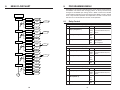
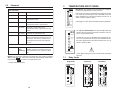
10
SAEM
)oreZ(
)tnioP(ECI
*ffO
noitcerroCCTyraropmeT-nO
)elcycrewoplitnU(
noitcerroCCTtnenamreP-dloH
)mumixaM/m
uminiM(OLIH
elbanEyalpsiD
*ffO
nO
6.2 Display Control
6.3 Measurement Control
*Factory Reset Default Values
*Factory Reset Default Values
)tneserpfi(4#yaleR&4#tnioPteS4PS
4-laV
eulaV*00001
)4esnopseR(4psR
tsyH
*yalD
hctL
%9.92ot*0
)*01.0(sdnoceS00.
06ot*0
evitcA
)4mralA(3-rlA
*IH
OL
FFO
)mralAnitonnehwetatS(4-tS
*DN
EN
LtcD
)seer(ged
nodesabdexiF)tiehnerhaF(F)suisleC(*C
CTroDTR
)hserfeR(hsrF
)*042(etunimrepsetadpu084ot1-eul
aV
dnaB
.eulavtnerrucmorfstnuoc99ot*0-eulaV
)ssenthgirB(tirB
S dna T ssenthgirbDELevomsworra
.yalpsidnodetaci
dnisaslevel5hguorht
)ssenthgirblluf*5(
15
The hold feature is used to freeze the display. When the contacts are shorted,
the display will “Hold” the last reading until the short is removed. It is recom-
mended that a mechanical switch or relay be used to activate the hold circuit,
solid state relays may give unexpected results. The hold circuit cannot be ex-
ternally powered.
No terminal can be above earth ground by more than 250Vrms. An external
fuse is recommended for safe operation, for AC supply, Slow Blow fuse at
.25A, Littlefuse Part No. 313.250 or equal. For DC supply Slow Blow fuse at
1.25A, Littlefuse Part No. 3131.25 or equal.
Hazardous voltages may be present. Disconnect power before making or re-
moving connections.
!
!

11
6.5 System Control
LtcS
yrotcaF(TESr/TCAF
)teseR
ehtteserlliwmetisihtgnitceleS(teseR
otnruterdnaseulavtluafedotecived
)unem
6.4 Output Control (If Present)
(The process meter will have pre-loaded coordinates)
LtcO
tuogoLA
MIL)timillacirtcele(IH
)*001(
)timillacirtcele(oL
)*0(
)efasliaF(SF)Am02otevom(IH
egnarrednUroegn
arrevO()Am4otevom(OL
*ffO
14
The relay cards are directly related to any alarms that occur on the Hawk 3.
The single relay is a “Form C” relay that activates in relationship to “SP1”.
The dual relay is a Form C” relay that activates in relationship to “SP1” &
“SP2”.
The quad relay is a “Form A” relay that activates in relationship to “SP1” through
“SP4”.
NOTE: “SP3” and “SP4” connections share a common.
All relay contacts are rated at 250VAC @ 5 amp maximum. The rating of the
relay contact is intended for resistive circuits only. Use a snubber circuit to
protect the contacts from inductive loads.
7.2 Frequently Asked Questions
What is a Form A or Form C relay?
The form A relay is a 1 contact switch that is either closed or open. The form C
relay has 2 contacts, one of which will be closed and one open. With the fac-
tory defaults used, N.O. on the relay means normally open when the Hawk 3 is
not in alarm. N.C. means normally closed when the Hawk 3 is not in alarm.
What does N.D. and N.E. do to the relay?
The effect of the relay can be reversed by setting the relay action to N.E. (nor-
mally energized) in the menu. When the Hawk 3 is not in alarm, the N.C.
contact will now be open and the N.O contact will be closed. Setting the alarm
response back to N.D. (normally de-energized) will put the contacts back to
their default state.
7.3 Power Supply Card
Universal AC Supply DC to DC Supply
HOLD
9-36VDC
10W
+
HOLD
~
85 - 250 VAC
10VA
50/60 Hz
IN
IN
~
HOLD
~
85-250VAC
10VA
50/60 Hz
IN
IN
~
3-1/2 Digit 120 VAC Supply
!
The AC power cards are meant to operate from standard 50/60 Hz line power.
The DC to DC power card is an isolated supply that can operate between 9
and 32 volts DC.

12
6.6 Password
)drowssaP(ssaP
*000.sseccAlluF
002ot100.teseryrotcafroelacsotsseccaoN
004ot102roteseryrotcaf,elacsotsseccao
N
.lortnoctnemerusaem
006ot104,teseryrotcaf,elacsotsseccaoN
.lortnoctuptuorolortnoctnemerusaem
008ot106,tes
eryrotcaf,elacsotsseccaoN
yalerrolortnoctuptuo,lortnoctnemerusaem
.lortnoc
999ot108yrtnedrowssaptpecxesse
ccaoN
999-eblliwsekortsyekerutufllA.tuokcoldapyeK
morfemoctsumsegnahcgnittesllA.derongi
fiylnoelbaliavasi
eciohcsihT.trop584-SR
derugifnocdnatneserpsidrac584-SReht
."lluF"rof
GHC
sap-uN
weN(
)drowssaP
sisihT.eulavw
enaotdrowssapehtegnahC
ehtgniretneyllufsseccusretfaylnoelbaliava
ottessidrowssapehtfirodrowssaptnerruc
.
000
NOTE: If you forget your password, turn power off in unit, press and hold the
T
key and the RE key. Turn power on and wait until the display reads “noPas”
then press the re key again to reset password to 000.
* Factory Reset default value
RESET
ENTER
RESET
ENTER
13
7. TEMPERATURE INPUT CARDS
RTD PT100: The resistance input card has been configured
to track the characteristics of a PT100 sensor.
Lead length error can be cancelled out by bringing the sensor
to 0 C (ice point) and using the “ICE” command to zero the
meter. (Remember to move the ICE capture from the “On” to
“Hold” in order to retain the data.)
Lead length error can also be cancelled using the guard wire.
7.2 J, K, E, T Thermocouple: The thermocouple input card
contains all the response information needed to read a J
type or K type thermocouple.
Lead length error can be cancelled out by bringing the cen-
sor to 0 C (ice point) and using the “ICE” command to zero
the meter. (Remember to move the ICE capture from “On” to
“Hold” to retain the data.
Never apply a voltage or current to these inputs as damage
will occur.
7.1 Relay Cards
!
RELAY OUT
N.C.
COM
N.O.
1
250V~ 5A
RELAY OUT
N.C.
COM
N.O.
1
N.O.
2
N.C.
COM
250V~ 5A
250V 5A
RELAY OUT
N.O.
COM
1
N.O.
COM
N.O.
N.O.
COM
2
3
4
Dual Relay
Quad RelaySingle Relay
IN LO
IN HI
TEMPERATURE
PT100
RTD
SENSE
THERMO
COUPLE
J,K,E,T
IN+
IN--
TEMPERATURE
-
 1
1
-
 2
2
-
 3
3
-
 4
4
-
 5
5
-
 6
6
-
 7
7
-
 8
8
-
 9
9
-
 10
10
-
 11
11
-
 12
12


Simpson Electric Hawk H340 User manual
- Category
- Wall clocks
- Type
- User manual
- This manual is also suitable for
Ask a question and I''ll find the answer in the document
Finding information in a document is now easier with AI
Related papers

Other documents
-
MB QUART PSC 316 User manual
-
 ANLY H3D-M User manual
-
 Hawk HA-EMS02 User & Installation Manual
-
 Texmate BL-40-TC Owner's manual
-
 Texmate LEOPARD Series User manual
-
Sigma Myriad ROS User manual
-
 Texmate BL-40PSF Owner's manual
-
Altronix RBR1224 Datasheet
-
M-system AS4V User manual
-
 Texmate BL-40PSF-PROCESS Owner's manual


