Page is loading ...
Not for
Reproduction
ATTACHMENT
OPERATOR’S MANUAL
1750600
Revision C
Model Description
1696450-00 Turbo, 44” & 50” Mower Deck w/Aluminum Spindles
1696450-01 Turbo, 44” & 50” Mower Deck w/Steel or Aluminum Spindles
1696450A-00 Turbo, 44” & 50” Mower Deck w/Steel or Aluminum Spindles
1696450A-01 Turbo, 44” & 50” Mower Deck w/Steel or Aluminum Spindles
Copyright © Briggs & Stratton Corporation
Milwaukee, WI, USA. All rights reserved.
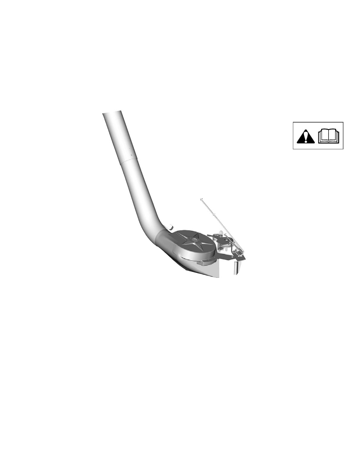
Turbo Vacuum System
For 44” and 50” Mower Decks with Aluminum and Steel Arbors
on Lawn Tractors and 50” Mower Decks with Steel Arbors on Zero Turn Riders
Not for
Reproduction
Manual Contents:
Operator Safety...............................................................2
Hardware and Parts Identification...............................5
Assembly ......................................................................8
Operation......................................................................20
Storage.........................................................................23
Warranty.......................................................................24
General Information
The illustrations in this document are representative.
Your unit may vary from the images displayed. LEFT and
RIGHT are referenced from the operator’s position.
All packaging, used oil, and batteries
should be recycled according to
applicable government regulations.
All language translations of this document are derived
from the original English source le.
Operator Safety
Safety Alert Symbol and Signal Words
The safety alert symbol is used to identify safety
information about hazards that can result in personal injury.
A signal word (DANGER, WARNING, or CAUTION) is
used with the alert symbol to indicate the likelihood and
potential severity of injury. In addition, a hazard symbol may
be used to represent the type of hazard.
DANGER indicates a hazard which, if not avoided,
will result in death or serious injury.
WARNING indicates a hazard which, if not
avoided, could result in death or serious injury.
CAUTION indicates a hazard which, if not avoided,
could result in minor or moderate injury.
NOTICE indicates an action that could result in damage to
the product.
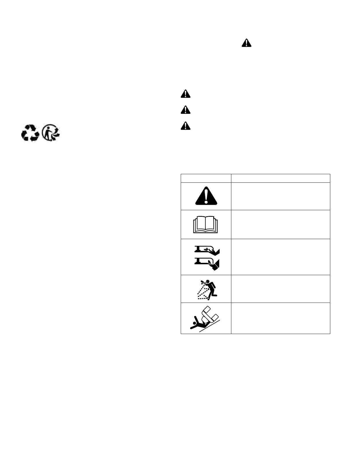
Hazard Symbols and Meanings
Symbol Meaning
Safety information about the hazards
that can result in personal injury.
Read the directions for use of the
product before operating.
Keep hands and feet away from deck.
Thrown object hazard.
Roll over hazard.
2

Not for
Reproduction
Operation Safety with Turbo
WARNING
Failure to read and follow the safety warnings and
instructions in this document and in the tractor operator’s
manual could result in death, serious injury, and/or
property damage.
The warnings and instructions must be read, understood,
and followed when setting-up, operating, servicing,
transporting, or storing the unit.
DANGER
• DO NOT operate the unit without either the entire
grass catcher or the deflector in place.
• Turn off the PTO to disengage the blades when not
mowing.
• DO NOT mow in reverse unless absolutely necessary.
Always look down and behind before and while
traveling in reverse.
DANGER
Amputation or Laceration Hazard
• If the mower stalls or the collection system plugs,
disengage the electric clutch (PTO), stop the engine
and remove the key. Set the parking brake. Wait for
moving parts to stop. Remove the foreign object or
clear the chute with a piece of wood before restarting
the engine. Never place hands into blower housing to
remove a jammed object.
• Disengage the electric clutch (PTO). Shut off the
engine, remove the key, and wait for all moving parts to
stop before attaching, adjusting, or disconnecting any
part of the collection system.
• DO NOT make adjustments or repairs while the
engine is running or blades are moving.
• DO NOT not place hands or feet near rotating parts.
WARNING
Thrown Objects Hazard
Do not open the cover while the blades are turning.
• Check the collection system to make sure it is bolted
tightly to the unit.
• Collector bags are subject to deterioration and wear
during normal use. Inspect the bag periodically for
tears, holes, or weak spots and replace with a new bag
that meets manufacturer’s durability standards.
WARNING
Loss of Control, Roll-over and Tipping
Hazard
• Use reduced speed on uneven ground and when
turning corners.
• Reduce loads on hillsides. It is recommended that the
collection system be kept only half full when mowing
any slopes. Start mowing on slopes when the collection
system is empty.
• Never operate on slopes greater than 17.6% (10°).
• Use a slow ground speed when driving onto a slope.
Avoid using brakes to control speed.
• Use caution when changing directions and DO NOT
start or stop the tractor while on a slope.
Operation Safety without Turbo
WARNING
For operation without the turbo, the deflector must be
properly installed in the down position and retained by the
spring latch.
3

Not for
Reproduction
Part No. 5103184
Safety Decals
Before operating the turbo unit, read and understand the
installed safety decals. The decals are provided to help you
avoid personal injury or damage to the product.
If any safety decals become damaged or illegible, order
replacements from your local authorized dealer.
Part No. 1700259
4
Not for
Reproduction
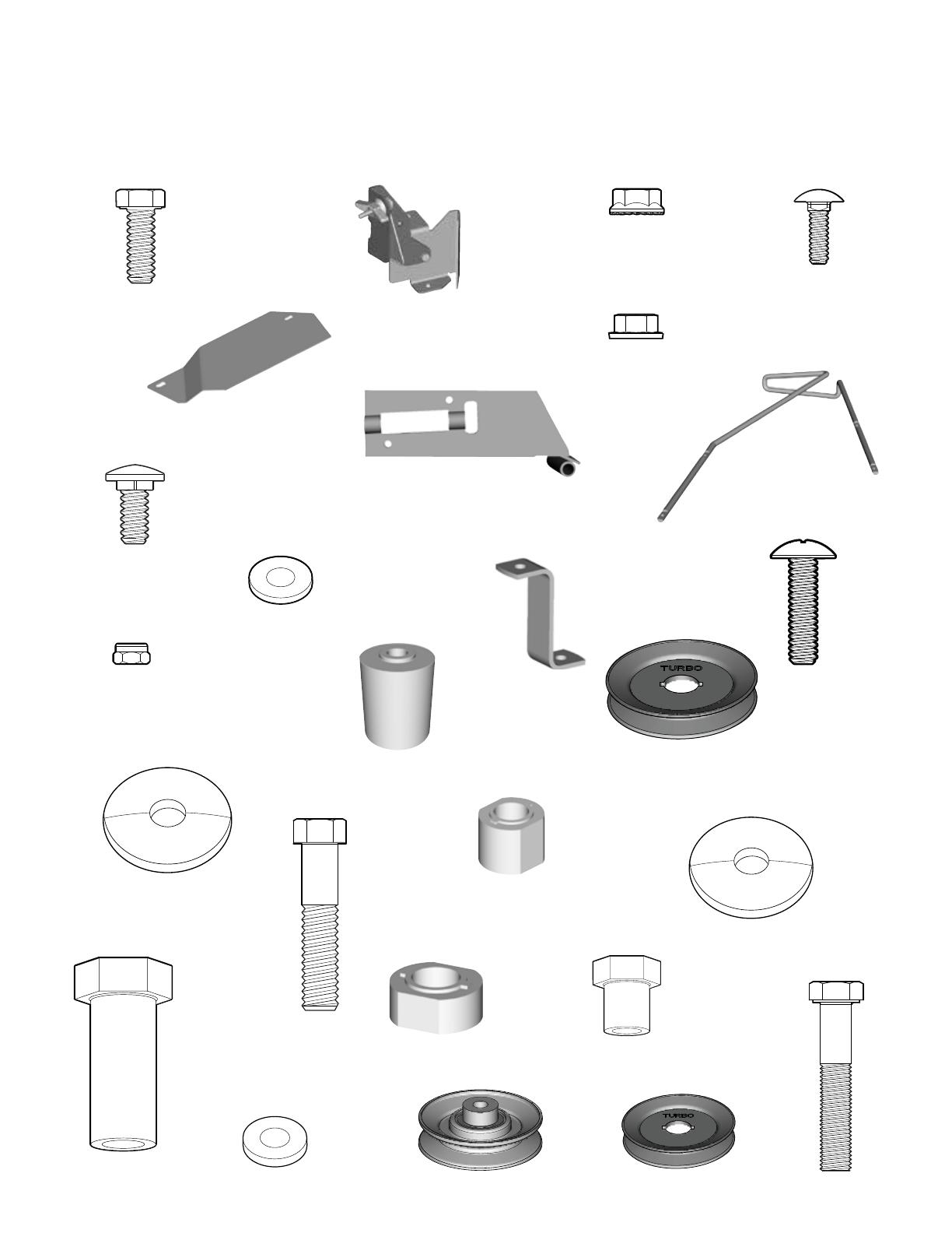
Hardware and Parts Identification
B - DISCHARGE
BAFFLE ASSEMBLY (Qty. 1)
A - CAPSCREW
.3125”-18 x .875” (Qty. 5)
C - NUT, Hex Flange
.3125”-18 (Qty. 5)
E - TURBO COVER
(Qty. 1)
D - BOLT, Carriage
.25”-20 x .75” (Qty. 2)
G - DEFLECTOR
SUPPORT ROD
(Qty. 1)
H - PIVOT BRACKET
(Qty. 1)
I - CAPSCREW
.3125”-18 x .75” (Qty. 1)
J - WASHER
.344” ID x .75” OD x .065 THK
(Qty. 4)
K - BELT
COVER SUPPORT
(Qty. 1)
L - SCREW, Phillips Head
10-24 x .75” (Qty. 13)
M - NUT, Nylock
#10-24 (Qty. 13)
R - SPACER, Pulley
1.28” Height (Qty. 1)
O - PULLEY
3.75” OD (Qty. 1)
F - NUT, Conical Washer
.25” - 20 (Qty. 2)
T - SLEEVE NUT
1.34” x 1.74” (Qty. 1)
U - SPACER, Pulley
.73” Height (Qty. 1)
N - SPACER, Hub
.97” Height (Qty. 1)
P - WASHER, Belleville
.475” ID x 1.75” OD x .156” THK
(Qty. 1) Q - CAPSCREW
.4375”-14 x 2.00”
(Qty. 1)
W - BOLT
.375”-16 x 2.00”
(Qty. 1)
V - SLEEVE NUT
.75” x 1.21” (Qty. 1)
X - WASHER
.406” ID x .875” OD x .083 THK
(Qty. 3)
S - WASHER, Belleville
.880” ID x 1.75” OD x .085” TK
(Qty. 1)
Y - PULLEY
3.00” OD (Qty. 1)
• Upper case letters identify the hardware and parts in the kit.
• Lower case letters identify the existing hardware and parts assembled before the start of the installation.
Z - PULLEY
.80” ID x 4.30” OD (Qty. 1)
5

Not for
Reproduction
AT - HAIR PIN
(Qty. 1)
AL - TURBO ASSEMBLY (Qty. 1)
AO - ROLLER
(Qty. 1)
AP - PUSH NUT
(Qty. 1)
AQ - BELT COVER,
44” Mower Deck
(Qty. 1)
AR - BELT COVER,
50” Mower Deck (Qty. 1)
AS - NUT, Keps
.3125” - 18 (Qty. 1)
Turbo Attachment
AM - TURBO BELT, 50” Mower Deck (Qty. 1)
Belt is pre-assembled on Turbo.
Size: 39” OD
AH - CARRIAGE BOLT
.312”-18 x 1.50” (Qty. 1)
AI - LOCK WASHER
.322” ID x .583” OD x .078THK
(Qty. 1)
AJ - BELT GUIDE
(Qty. 1)
AK - SPACER
.328” ID x .50” OD x .625 LG
(Qty. 1)
AA - L-BRACKET
(Qty. 1)
AE - Z-BRACKET
(Qty. 1)
AF - NUT, Whiz Lock
.375” - 16 (Qty. 1)
AD - SPACER
.390” ID x .625” OD x .265 THK
(Qty. 1)
ZZ - WASHER
.406” ID x 1.0” OD x .130 THK
(Qty. 1)
AB - BRACKET, Idler Pulley
(Qty. 1)
AC - NUT, Center Lock
.375” - 16 (Qty. 1)
AG - SCREW
.3125”-18 x 1.00” (Qty. 2)
AN - TURBO BELT, 44” Mower Deck (Qty. 1)
Size: 37” OD
6
Not for
Reproduction
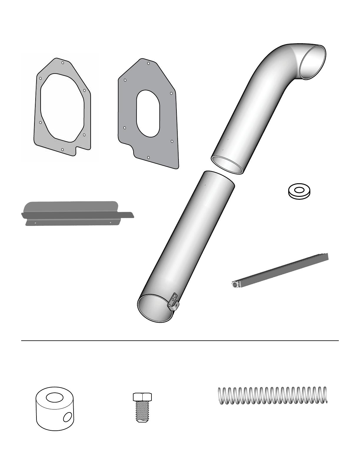
BA - FLANGE SEAL
(Qty. 1)
BB - COVER SEAL
(Qty. 1)
BC - UPPER TUBE
(Qty. 1)
BD - LOWER TUBE
(Qty. 1)
BE - WASHER
.50” OD” x .20” ID” x .05” THK
(Qty. 2)
BG - COVER EDGING
(Qty. 1)
BF - DEFLECTOR PLATE
(Qty. 1)
Catcher
CA - SET COLLAR
(Qty. 1)
CC - SPRING
(Qty. 1)
CB - SET SCREW
.3125”-18” x .50”
(Qty. 1)
Models with Frame-Hung Mower Decks
7
Not for
Reproduction
Assembly
WARNING
Disengage the electric clutch (PTO). Shut off the engine,
remove the key, and wait for all moving parts to stop
before attaching, adjusting, or disconnecting any part of
the collection system.
Remove the Deector
Note: To ease assembly, remove the mower deck from the
tractor.
Lawn Tractors with 44” or 50” Mower Decks
Remove the carriage bolts, push nuts, spacer, washer, nuts
(a, Figure 1), deflector rod (b), and the deflector (c). Keep
the deflector.
b
a
a
c
Figure 1
Zero Turn Riders with 50” Mower Deck
Remove the carriage bolts, push nuts, washers, nuts (a,
Figure 2), deflector rod (b), and the deflector (c). Keep the
deflector.
b
a
a
c
Figure 2
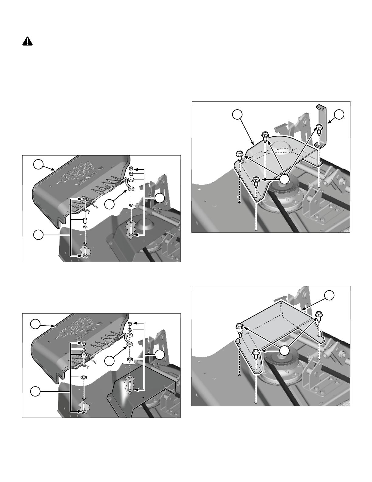
Remove the Pulley Cover and the Upstop
Lawn Tractors with 44” or 50” Mower Decks
1. Put the mower deck in the lowest position.
44” mower deck: Remove and discard the four taptites
(a, Figure 3) and the pulley cover (b).
50” mower deck: Remove the four taptites (a, Figure
3) from the upstop (c) and pulley cover (b). Keep the
upstop and one taptite. Discard the pulley cover and the
remaining taptites.
b
a
c
Figure 3
Zero Turn Riders with 50” Mower Decks
1. Put the mower deck in the lowest position.
2. Remove and discard the three taptites (a, Figure 4) and
the pulley cover (b).
b
a
Figure 4
Lawn Tractors with 50” Mower Decks
2. Install the upstop removed and the taptite (b, Figure 5)
removed in Figure 3.
8
Not for
Reproduction
Install the Discharge Bae
All Mower Decks
1. Install the capscrew (A, Figure 5) through the hole in
the bottom of the stone guard (a), and discharge baffle
assembly (B). Install the nut (C) and tighten with your
fingers.
C
B
a
A
Figure 5
2. Install the two capscrews (D, Figure 6) through the
inside of the mower deck, discharge baffle assembly
(B), and the turbo cover (E) . Install the two nuts (F).
3. Tighten the nut (C) installed in Step 1.
B
E
D
F
C
Figure 6
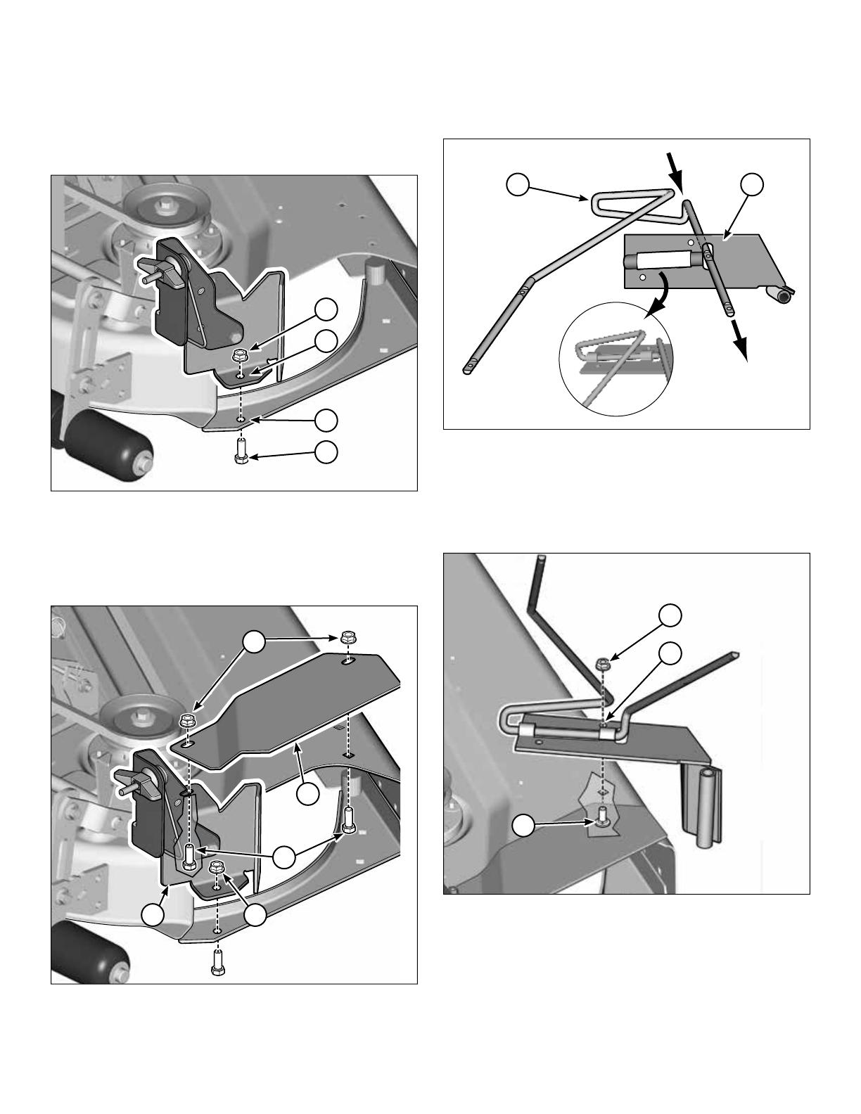
Install the Deector Support Rod and the
Pivot Bracket
1. Put the deflector support rod (G, Figure 7) into the slot
of the pivot bracket (H).
H
G
Figure 7
2. Note: To ease assembly, remove the plug from the front
hole.
Install the capscrew (I, Figure 8) through the bottom of
the mower deck and the middle hole of the pivot bracket
(H). Install the nut (C).
I
C
H
Figure 8
9
Not for
Reproduction
3. Install the capscrew (A, Figure 9) and washer (J),
through the bottom of the mower deck, the inner hole
of the pivot bracket (H), and the belt cover support (K).
Install the nut (C).
CK
A
J
H
Figure 9
4. Drill four 13/64” holes (a, Figure 10) through the
locations of the molded holes in the bottom of the
deflector (b).
b
a
Figure 10
5. Install the screws (L, Figure 11) through the holes of the
deflector support rod (G), and the holes drilled in the
previous step. Install the nuts (M).
L
MM
G
Figure 11
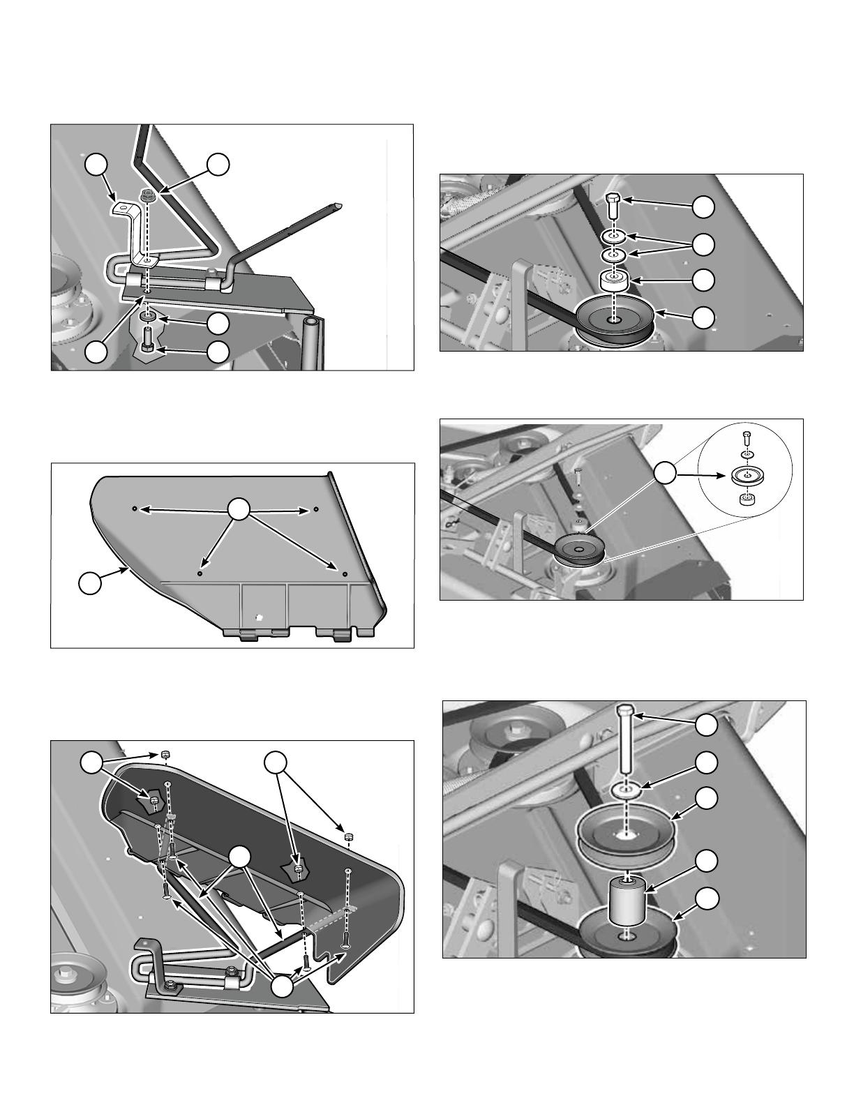
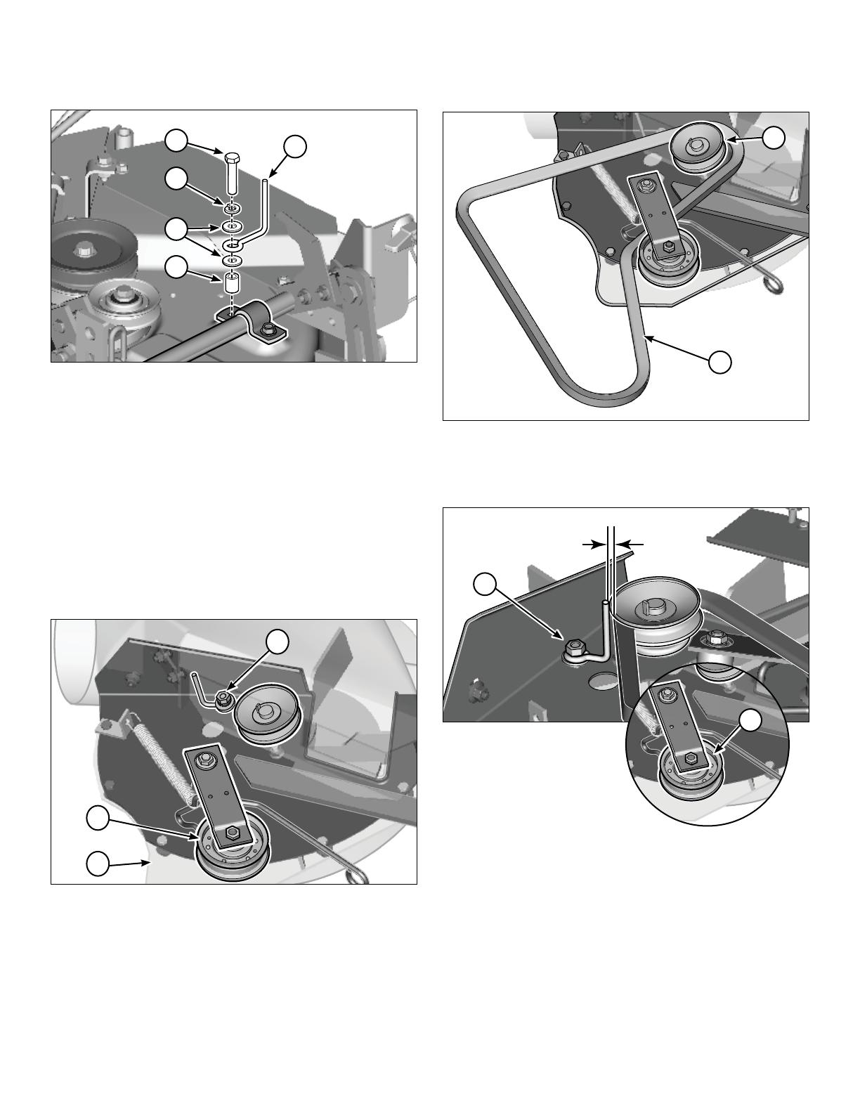
Assemble the Pulley
Lawn Tractors with 44” and 50” Mower Decks with
Aluminum Arbors
1. Use a block of wood to prevent blade rotation. Remove and
discard the capscrew (a, Figure 12), belleville washers (b)
and the spacer (c) from the right arbor pulley (d).
Figure 12
Note: On RegentTM models, remove and discard the right
arbor pulley (d, Figure 13).
Figure 13
2. Install the spacer (N, Figure 14), pulley (O), belleville
washer (P), and capscrew (Q) on the existing pulley (d).
Tighten the capscrew (Q) to 50-60 lb-ft (68- 81Nm).
Note: On RegentTM models, install the pulley (Z, Figure 14).
Figure 14
b
a
c
d
P
Q
O
Z
N
d
10

Not for
Reproduction
Lawn Tractors with 44” and 50” Mower Decks with
Steel Arbors
1. Use a block of wood to prevent blade rotation. Remove
the locknut (a, Figure 15), belleville washers (b) and the
right arbor pulley (c).
c
a
b
Figure 15
2. Put the spacer (R, Figure 16), pulley (O) and belleville
washer (S) on the existing pulley (c). Align the notches
on the pulleys with the ridges on the spacer.
3. Install the sleeve nut (T). Tighten to 55-70-ft. lbs (68- 81 Nm).
O
R
T
S
c
Figure 16
Zero Turn Riders with 50” Mower Decks
1. Use a block of wood to prevent blade rotation. Remove
the locknut (a, Figure 17) and belleville washers (b)
from the right arbor pulley (c).
c
a
b
Figure 17
2. Put the spacer (U, Figure 18), pulley (O), and belleville
washer (S) onto the existing pulley (c). Align the notches
in the pulley with the ridges in the spacers
3. Secure with the sleeve nut (V). Torque to 55-70 lb-ft. (68-
81 Nm).
O
U
V
S
c
Figure 18
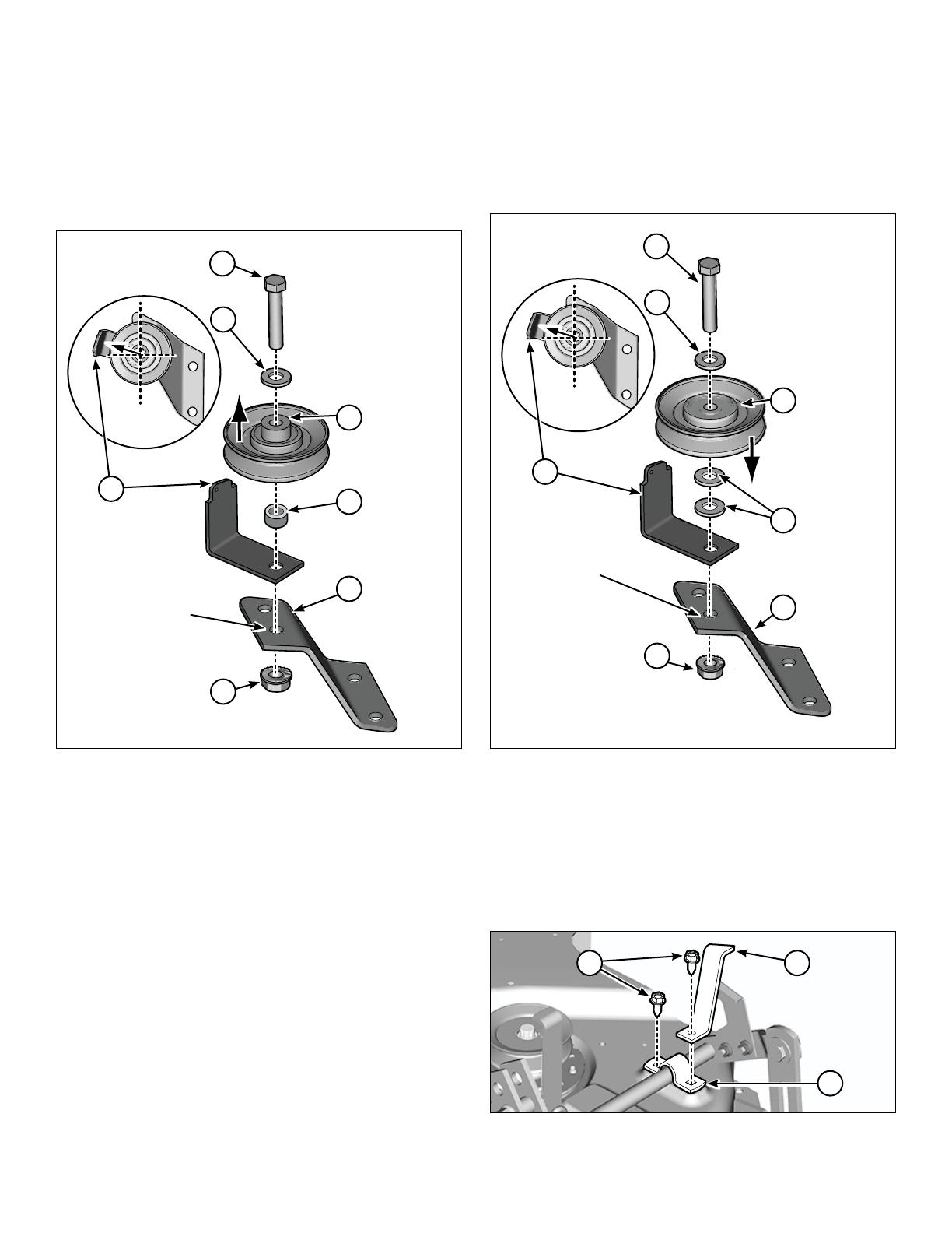
Assemble the Idler Pulley Bracket
Lawn Tracters with 44” and 50” Mower Decks with
Aluminum Arbors
1. Install the bolt (W, Figure 19), washer (X), pulley (Y) and
washer (ZZ) onto the the L-bracket (AA) and into the
correct hole of the idler pulley bracket (AB).
Note: On BroadmoorTM, PrestigeTM and ConquestTM
models, do not use the washer (ZZ).
Make sure the pulley and the L-bracket (AA) is in the
correct position as shown in the inset.
2. Install the center locknut (AC).
44” 50”
AB
AA
W
ZZ
X
Y
AC
Figure 19
11
Not for
Reproduction
Lawn Tractors with 44” and 50” Mower Decks with
Steel Arbors
1. Install the bolt (W, Figure 20), washer (X), pulley (Y) and
spacer (AD) onto the L-bracket (AA) and into the correct
hole of the idler pulley bracket (AE).
Make sure the pulley points up and the L-bracket is in
the correct position as shown in the inset.
2. Install the whiz lock nut (AF).
X
W
AE
AD
44”/50”
Y
AA
AF
Figure 20
Zero Turn Riders with 50” Mower Decks
1. Install the bolt (W, Figure 21), washer (X), pulley (Y) and
washers (X) onto the the L-bracket (AA) and into the
correct hole of the idler pulley bracket (AE).
Make sure the pulley points down and the L-bracket is in
the correct position as shown in the inset.
2. Install the whiz lock nut (AF).
X
W
AE
50” ZT
Y
AA
AF
X
Figure 21
Remove the Height-of-Cut Indicator
All Mower Decks
1. Remove the two taptites (a, Figure 22) from the height-
of-cut indicator (b) and the strap (c). The strap remains
in place. Keep the height-of-cut indicator and the
discard taptites.
ba
c
Figure 22
12

Not for
Reproduction
Install the Idler Pulley Bracket and the
Height-of-Cut Indicator
Lawn Tractors with 44” and 50” Mower Decks with
Aluminum Arbors
1. Install the screw (AG, Figure 23) into the inner hole of
the idler pulley bracket (AB) and the strap (a). Tighten
the screw with your figurers.
AG
AB
a
Figure 23
2. Install the other screw (AG, Figure 24) into the height-
of-cut indicator (b), outer hole of the idler pulley bracket
(AB) and the strap. Tighten the two screws.
AG
AB
b
Figure 24
Install the Idler Pulley Bracket
Lawn Tractors with 44” and 50” Mower Decks with
Steel Arbors
Zero Turn Riders with 50” Mower Decks
1. Remove and discard the two taptites (a, Figure 25) from
the two locations (b) on the arbor housing.
b
a
Figure 25
2. Put the two capscrews (A, Figure 26) through the
bottom of mower deck, arbor housing (c) and the
Z-bracket (AE). Secure with the nuts (C).
c
C
A
AE
Figure 26
3. Remove and discard the front taptite (d, Figure 27)
securing the strap (e) to the mower deck.
d
e
Figure 27
AG
AB
13
Not for
Reproduction
4. Install the capscrew (AH, Figure 28) into the lock
washer (AI), washer (J), belt guide (AJ), washer (J),
spacer (AK), strap and the mower deck.
AH
AI
J
AJ
AK
Figure 28
Install the Turbo Belt
44” Mower Decks Only
50” Mower Deck belt is pre-assembled.
Refer to the part number printed on the inner side of
the belt for the correct size.
50” - (AM) 39” OD
44” - (AN) 37” OD
1. Loosen the hardware securing the turbo belt guide (a,
Figure 29) and the idler pulley assembly (b) on the turbo
assembly (AL).
AL
b
a
Figure 29
2. Remove the 50” turbo belt (AM).
3. Install the belt (AN Figure 30) around the idler pulley
assembly and the turbo pulley (c).
AN
c
Figure 30
4. Tighten the hardware (a and x, Figure 31) securing the
turbo belt guide and the idler pulley assembly. Make
sure the belt guide is installed 1/16” away from the belt.
a
Figure 31
x
14
Not for
Reproduction
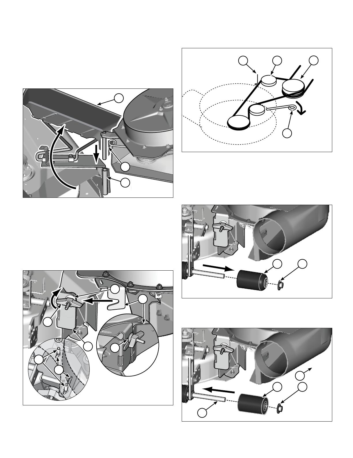
Install the Turbo
All Mower Decks
Note: The belt will be very tight the first time it is installed,
but will gradually loosen with use.
1. Rotate the deflector (a, Figure 32) to the upright
position.
2. Install the mounting pin on the turbo assembly (AL) and
into the pivot bracket (H).
a
AL
H
Figure 32
3. Loosen the wing nut (b) on the discharge baffle
assembly (B, Figure 33).
4. Install the latch on the turbo assembly (AL) between the
cup washer (c) and the support on the discharge baffle
assembly (B).
Note: The latch should be against the mounting bracket.
If necessary, loosen hardware (d) and adjust the turbo
position in the slots (e).
c
AL
B
b
c
d
e
Figure 33
5. Tighten the wing nut on the discharge baffle assembly.
6. Pull the idler arm (e, Figure 34) to loosen the tension
and install the turbo belt onto pulley (O) and pulley (Y).
Make sure the belt guide (AJ) is approximately 1/8”
away from the belt.
Y
e
O
AJ
Figure 34
Install the Roller
All Mower Decks
1. Remove and discard the push nut (a, Figure 35) and the
roller (b) from the right side of the tractor.
ab
Figure 35
2. Slide the new roller (AO, Figure 36) onto the roller shaft
assembly (c) and install the push nut (AP).
c
APAO
Figure 36
c
15
Not for
Reproduction
WARNING
Disengage the electric clutch (PTO). Shut off the engine,
remove the key, and wait for all moving parts to stop
before attaching, adjusting, or disconnecting any part of
the collection system.
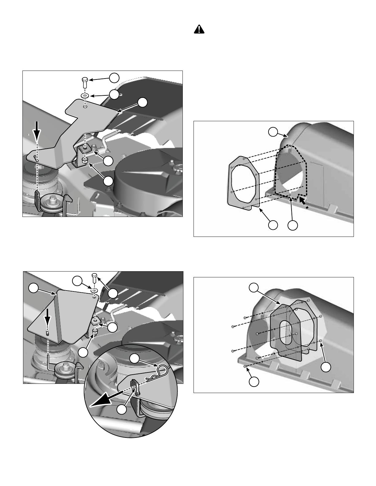
Install the Cover Seal and Tube
1. Put the flange seal (BA, Figure 39) onto the grass catcher
cover (a) as a template. Make sure the flange seal is
down to the right and against the grass cover ridge.
2. Drill six 13/64” holes (b) on the grass catcher cover.
BA b x 6
a
Figure 39
3. Align the flange seal and the cover seal (BB, Figure 40)
with the drilled holes on the inside of the grass catcher
cover. Install the screws (L) and the nuts (M).
M x 6
BB
L x 6
Figure 40
Install the Belt Cover Plate
Lawn Tractors 44” with Mower Decks
1. Put the capscrew (A, Figure 37) through the washer
(J), the belt cover (AQ), and the belt cover support (K).
2. Install the keps nut (AS).
K
A
J
AS
44” AQ
Figure 37
Lawn Tractors and Zero Turn Riders with 50” Mower
Decks
1. Put the capscrew (A, Figure 38) through the washer
(J), the belt cover (AR), and the belt cover support (K).
2. Install the keps nut (AS).
Figure 38
J
AR
AS
50”
A
AT
AA
K
16

Not for
Reproduction
5. Put the upper tube (BC, Figure 41) onto the lower tube
(BD) and align the holes.
6. From the inside of the tube, put the screw (L) through
the washer (BE), lower and upper tubes, and the
washer (BE). Install the nut (M).
BC
BD
M
L
BE
BE
Figure 41
Install the Triple Collector Plate and Edging
1. Hold the deflector plate (BF, Figure 42) on the inner
edge of the cover and use as a template to mark the
new hole locations.
2. Drill two 13/64” holes in the marked locations.
3. Put he screws (L) through holes on outer side of the
cover and the deflector plate. Secure with the nuts (M).
M L
BF
Figure 42
4. Start at the edge of the hinge (a) and put the cover
edging (BG, Figure 43) onto the cover.
a
BG
Figure 43
Install the Cover and the Collector Bag
Refer to the Catcher Operator’s Manual.
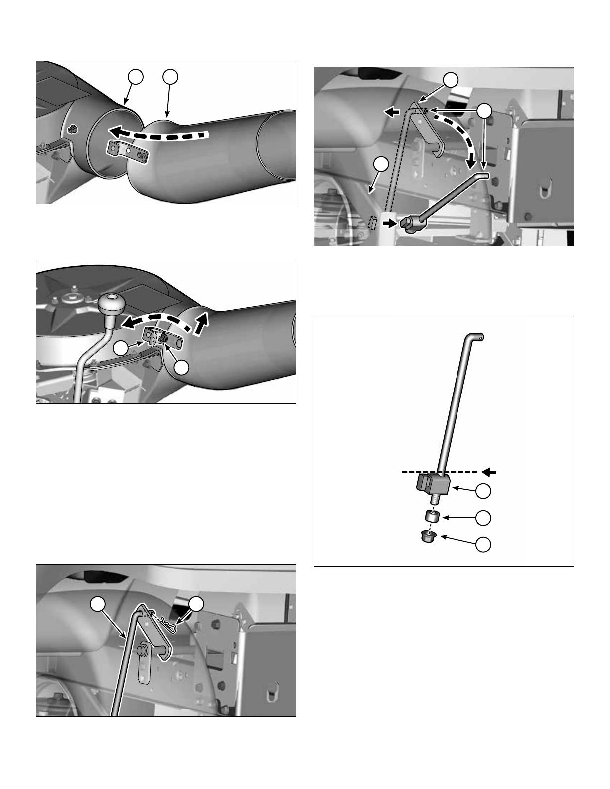
Tube Installation
1. Put the upper tube (BC, Figure 44) into the cover seal (BB).
Note: To ease installation, rotate the discharge end of
the tube assembly.
BB
BC
Figure 44
17
Not for
Reproduction
2. Put the intake end of the lower tube (BD, Figure 45)
onto the outlet of the turbo (AL).
AL BD
Figure 45
3. Lift the spring clip (a, Figure 46) above the nut and
capscrew (b). Push to lock into place.
a
b
Figure 46
Adjust the Lift Rod
Models with Frame Hung Mowers
Note: This installation procedure is on the left side of the
tractor when the turbo and tubes are not installed on the
mower deck.
1. When the mower is in the lowest position, put blocks of
wood under the mower deck to release tension in the
mower lift
2. Remove the hair pin (a, Figure 47) from the lift rod (b).
ab
Figure 47
3. Pull out the lift rod (b, Figure 48) from the lift arm (c) and
turn and remove from the lift bar (d).
c
b
d
Figure 48
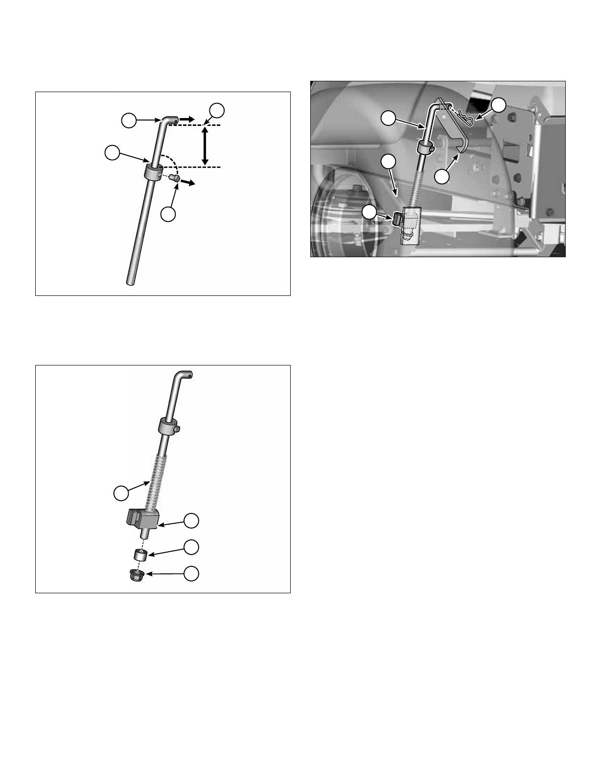
4. Remove the locknut (e, Figure 49) and the spacer (f).
5. Put a mark at the location of the special nut (g) and
remove it.
g
e
f
Figure 49
18
Not for
Reproduction
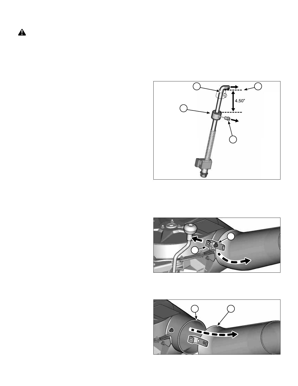
6. Put the set collar (CA, Figure 50) onto the lift rod (b),
4.50” from the bottom of the rod tip (h).
7. Install the set screw (CB) into the set collar and in the
direction of 90° from the rod tip.
h
CA
CB
b
4.50”
90°
Figure 50
8. Install the spring (CC, Figure 51) and the special nut (g)
in the location marked in Step 5.
9. Install the spacer (f) and the locknut (e).
CC
g
e
f
Figure 51
11. Install the special nut (h, Figure 52) onto the lift bar (k).
12. Put the lift rod (i) onto the lift arm (l) and install the hair
pin (m).
m
l
i
k
h
Figure 52
19
Not for
Reproduction
Remove the Turbo
Adjust the Lift Rod on Models with Frame-Hung
Mowers
1. Put a mark at the location of the set collar (CA, Figure
53) on the lift rod (b).
2. Loosen the set screw (CB) and put set collar at the top
of the rod tip (h).
3. Install the set collar in place with set screw pointing 90°
from rod tip.
.
CA
CB
b h
Figure 53
Tube and Turbo Removal
1. Lift the spring clip (a, Figure 54) over the nut and the
capscrew (b).
a
b
Figure 54
2. Slide the intake end of the lower tube (BD, Figure 55)
out of the turbo (AL).
AL BD
Figure 55
Operation
WARNING
Disengage the electric clutch (PTO). Shut off the engine,
remove the key, and wait for all moving parts to stop
before attaching, adjusting, or disconnecting any part of
the collection system.
Before Operation
Remove all sticks, stones, or other debris, which can get
caught or thrown by the mower blades.
For best results, mow when the grass is dry. Wet grass can
clump and block the mower and grass catcher.
BEFORE YOU BEGIN MOWING, make sure the bottom of
the mower and the bottom of the catcher cover are clear of
grass and debris.
For satisfactory grass collection, air circulation from the
mower deck, through the chute, and into the grass catcher
is very important.
Make sure there are tight connections between the mower
deck, turbo housing, tubes, and grass catcher cover.
Mowing with the Bagger
Always operate the riding mower with the throttle at full
speed.
If grass is long, slow the ground speed and cut half the
width of the mower to prevent blockage. Another method
is to cut once with the deck in a high setting and then cut
again with the deck in a low setting.
Do not open the cover with the mower engaged.
If a large amount of cut grass ejects from the bottom of the
deck, the tube may be blocked or the bags may be full.
Stop the rider, disengage the PTO, stop the engine and
then empty the catcher or remove the blockage from the
tube.
Recommended Accessories
Use front counterweights if operating on slopes when a rear
attachment is installed. Two rear wheel weights can also be
added. Never operate on slopes greater than 17.6% (10°).
20
/