Page is loading ...

INSTALLATION INSTRUCTIONS
OUTDOOR BACKSTOP WITH 4'-0" EXTENSION
No. 00174-_ _ _
WARNING
READ ALL INSTRUCTIONS THOROUGHLY BEFORE ATTEMPTING TO INSTALL THIS EQUIPMENT.
INSTALLATION / ASSEMBLY OF THIS EQUIPMENT MUST BE DONE ONLY BY ADULTS, WHO ARE PHYSICALLY
CAPABLE OF DOING SO.
PARTS LIST
Item No. Part No. Quantity Description
1 VARIOUS 1 Fan Backboard
2 VARIOUS 1 Goal
3 UPRT 00156 0G0 1 Post
INST 00064 082
¤2017 PORTER ATHLETIC EQUIPMENT COMPANY. ALL RIGHTS R0ESERVED. 12-20-2017
INSTALLER NOTE:
Upon completion of the installation/assembly of this backstop, make sure
this instruction manual is in the possession of the owner or facility
manager, to save for future reference, and to order replacement parts.
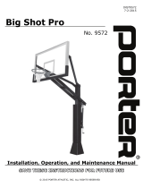
4'-0"

2
Detail "A"
LEVEL
LEVEL
2x6 BOARD
APPROX. 10'-3" Lg.
2 PIECES
9'-5"
DIMENSION
FROM PLAYING
SURFACE TO
BOTTOM OF
ATTACHMENT
PLATE MUST BE
HELD TO
ACQUIRE
OFFICIAL 10'-0"
GOAL HEIGHT
PLAYING
SURFACE
FILL BOTTOM OF FOOTING
WITH GRAVEL AS
REQUIRED TO HOLD POST
AT PROPER POSITION
BOLT 2x6's THRU
SLOTS IN POST
MOUNTING PLATE
3'-0"±
2'-0"
DIA.
3'-6" DEEP
20°
WARNING
READ ALL WARNINGS THOROUGHLY BEFORE USING THIS EQUIPMENT.
FAILURE TO COMPLY WITH THE FOLLOWING INSTRUCTIONS AND WARNINGS MAY RESULT IN SERIOUS
INJURIES AND/OR PROPERTY DAMAGE.
xDO NOT HANG on the rim or any part of system, including backboard, support braces or net.
xDuring play, especially when performing dunk-type activities, keep player's face away from the backboard, rim and net.
Serious injuries could occur if teeth/face come in contact with backboard, rim or net. All players must wear a mouth guard
when performing dunk-type activities.
xDo not slide, climb or play on pole.
xDuring play, do not wear jewelry (rings, watches, necklaces, etc.). These objects may entangle in net.
xKeep organic material away from base of post. Grass, litter, etc. could cause corrosion and/or deterioration.
xCheck post system for signs of corrosion (rust, pitting, chipping, etc.) and repaint with exterior enamel paint. If rust has
penetrated through the steel anywhere, replace post immediately.
xCheck system before each use for loose hardware, excessive wear, and signs of corrosion, and repair before use.
xCheck system before each use for instability.
xNever allow play on damaged equipment.
THE OWNER OF THIS EQUIPMENT IS RESPONSIBLE TO ENSURE THAT ALL INDIVIDUALS FOLLOW THESE
SAFETY AND OPERATING INSTRUCTIONS TO AVOID INJURIES OR PROPERTY DAMAGE. PROPER USE AND
SUPERVISION OF THIS EQUIPMENT IS ESSENTIAL TO HELP REDUCE THE POSSIBILITY OF ACCIDENTS OR
INJURIES.
NOTE
These instructions detail installing a No. 174 Backstop permanently in a concrete footing. If using a No. 174 Backstop with an
outdoor ground sleeve, consult factory for information on special post. DO NOT PROCEED.
INSTALL POST
1. Check all items against Parts
List on Page 1 to ensure all
parts and hardware are
available to complete the
installation.
2. Locate center position of
post. CAUTION – Contact
your local utility companies
to locate buried electrical,
gas, water lines, etc.
BEFORE DIGGING HOLE
FOR FOOTING. Also,
check for overhead utilities.
3. Dig a footing 2'-0" in
diameter by 3'-6" in depth,
centered on the final location
of the post. Note – Footing
size may have to be
increased depending on soil
conditions. See Detail "A".
4. Using at least two adults, tip
the bottom end of the post
into the footing hole, and
raise it to the vertical
position. See Detail "A".

3
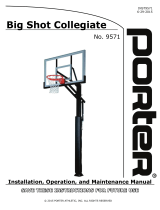
Detail "B"
3"
12"
PLAYING
SURFACE
5. Center the post in the hole. Shore it up, making sure the post is level, plumb, and at the proper height above the playing surface.
A suggested method of shoring is shown in Detail "A".
6. Pour concrete into the hole (approximately .41 cubic yards), tamping as it
is poured to eliminate air pockets. Slope top of footing upward toward
post so that top of footing at post is approximately 1/2" above playing
surface. Slope footing away from post, to a point that is 3" below the
playing surface. See Detail "B". This will ensure proper drainage,
reducing the possibility of corrosion of the steel post. Do not cover the
footing at the post with dirt, sod or anything else that could hold
moisture.
7. Allow concrete to cure at least 24 hours before proceeding.
ASSEMBLE BACKBOARD AND GOAL
8. Assemble backboard and goal to post using the four bolts furnished with the goal. Lay a level horizontally across the top of the
backboard and across the goal. Rotate backboard and goal as required until both are level. When level, tighten hardware
securely.
9. Assembly of backstop is now complete. Install optional post padding as required.
WWW.PORTERATHLETIC.COM
(888) 277-7778
SAVE THESE INSTRUCTIONS FOR FUTURE USE
WARNING: This product can expose you to Titanium Dioxide,
which is known to the State of California to cause cancer.
For more information go to www.p65warnings.ca.gov.
E
/