Page is loading ...

Pneumatic Drinking System (PDS) Control
Installation and Operators Manual
4-32 Station
Chore-Tronics
®
3 PDS
™
(Part No. 56039-X)
PDS
™
4 & 8 Station
(Part No. 52430-X)
12-40 Station PDS
™
(Part No.54373-X)
MW2467BFebruary 2020

Limited Warranty Pneumatic Drinking System (PDS) Control
2
MW2467B
Chore-Time Group, a division of CTB, Inc. (“Chore-Time”) warrants new CHORE-TIME Cage and Cage Watering
Components manufactured by Chore-Time to be free from defects in material or workmanship under normal usage and
conditions, for One (1) year from the date of installation by the original purchaser (“Warranty”). If such a defect is
determined by Chore-Time to exist within the applicable period, Chore-Time will, at its option, (a) repair the Product or
Component Part free of charge, F.O.B. the factory of manufacture or (b) replace the Product or Component Part free of
charge, F.O.B. the factory of manufacture. This Warranty is not transferable, and applies only to the original purchaser of
the Product.
CONDITIONS AND LIMITATIONS
THIS WARRANTY CONSTITUTES CHORE-TIME’S ENTIRE AND SOLE WARRANTY AND CHORE-TIME
EXPRESSLY DISCLAIMS ANY AND ALL OTHER WARRANTIES, INCLUDING, BUT NOT LIMITED TO,
EXPRESS AND IMPLIED WARRANTIES, INCLUDING, WITHOUT LIMITATION, WARRANTIES AS TO
MERCHANTABILITY OR FITNESS FOR PARTICULAR PURPOSES. CHORE-TIME shall not be liable for any direct,
indirect, incidental, consequential or special damages which any purchaser may suffer or claim to suffer as a result of any
defect in the Product. Consequential or Special Damages as used herein include, but are not limited to, lost or damaged
products or goods, costs of transportation, lost sales, lost orders, lost income, increased overhead, labor and incidental costs,
and operational inefficiencies. Some jurisdictions prohibit limitations on implied warranties and/or the exclusion or
limitation of such damages, so these limitations and exclusions may not apply to you. This warranty gives the original
purchaser specific legal rights. You may also have other rights based upon your specific jurisdiction.
Compliance with federal, state and local rules which apply to the location, installation and use of the Product are the
responsibility of the original purchaser, and CHORE-TIME shall not be liable for any damages which may result from non-
compliance with such rules.
The following circumstances shall render this Warranty void:
· Modifications made to the Product not specifically delineated in the Product manual.
· Product not installed and/or operated in accordance with the instructions published by the CHORE-TIME.
· All components of the Product are not original equipment supplied by CHORE-TIME.
· Product was not purchased from and/or installed by a CHORE-TIME authorized distributor or certified
representative.
· Product experienced malfunction or failure resulting from misuse, abuse, mismanagement, negligence, alteration,
accident, or lack of proper maintenance, or from lightning strikes, electrical power surges or interruption of
electricity.
· Product experienced corrosion, material deterioration and/or equipment malfunction caused by or consistent with
the application of chemicals, minerals, sediments or other foreign elements.
· Product was used for any purpose other than for the care of poultry and livestock.
The Warranty and Extended Warranty may only be modified in writing by an officer of CHORE-TIME. CHORE-TIME
shall have no obligation or responsibility for any representations or warranties made by or on behalf of any distributor,
dealer, agent or certified representative.
Effective: April, 2014
Chore-Time Group
A division of CTB, Inc.
PO Box 2000
Milford, Indiana 46542-2000 USA
Phone (574) 658-4101 Fax (877) 730-8825
E-mail: www.choretimepoultry.com
Internet: poultr[email protected]
Limited Warranty

Contents
Topic Page
MW2467B
3
Limited Warranty. . . . . . . . . . . . . . . . . . . . . . . . . . . . . . . . . . . . . . . . . . . . . . . . . . . . . . . . . . . . . . . . 2
About This Manual. . . . . . . . . . . . . . . . . . . . . . . . . . . . . . . . . . . . . . . . . . . . . . . . . . . . . . . . . . . . . . . 5
Safety Information . . . . . . . . . . . . . . . . . . . . . . . . . . . . . . . . . . . . . . . . . . . . . . . . . . . . . . . . . . . . . . . 5
Safety Instructions . . . . . . . . . . . . . . . . . . . . . . . . . . . . . . . . . . . . . . . . . . . . . . . . . . . . . . . . . . . . . . . 6
Follow Safety Instructions . . . . . . . . . . . . . . . . . . . . . . . . . . . . . . . . . . . . . . . . . . . . . . . . . . . . . . . . . . . . . . 6
Decal Descriptions . . . . . . . . . . . . . . . . . . . . . . . . . . . . . . . . . . . . . . . . . . . . . . . . . . . . . . . . . . . . . . . . . . . . 6
DANGER: Electrical Hazard . . . . . . . . . . . . . . . . . . . . . . . . . . . . . . . . . . . . . . . . . . . . . . . . . . . . . . . . 6
General. . . . . . . . . . . . . . . . . . . . . . . . . . . . . . . . . . . . . . . . . . . . . . . . . . . . . . . . . . . . . . . . . . . . . . . . . 6
Support Information . . . . . . . . . . . . . . . . . . . . . . . . . . . . . . . . . . . . . . . . . . . . . . . . . . . . . . . . . . . . . . . . . . . 6
Product Configurations . . . . . . . . . . . . . . . . . . . . . . . . . . . . . . . . . . . . . . . . . . . . . . . . . . . . . . . . . . . . . . . . . 6
System Layout. . . . . . . . . . . . . . . . . . . . . . . . . . . . . . . . . . . . . . . . . . . . . . . . . . . . . . . . . . . . . . . . . . . 7
Multiple House Layout . . . . . . . . . . . . . . . . . . . . . . . . . . . . . . . . . . . . . . . . . . . . . . . . . . . . . . . . . . . . . . . . . 7
Broiler System Layout . . . . . . . . . . . . . . . . . . . . . . . . . . . . . . . . . . . . . . . . . . . . . . . . . . . . . . . . . . . . . . . . . 7
Layer System Layout . . . . . . . . . . . . . . . . . . . . . . . . . . . . . . . . . . . . . . . . . . . . . . . . . . . . . . . . . . . . . . . . . . 8
One Water Line Per Tier, One Regulator Per Tier . . . . . . . . . . . . . . . . . . . . . . . . . . . . . . . . . . . . . . . . 8
Two Water Lines per Tier, Two Regulators Per Tier . . . . . . . . . . . . . . . . . . . . . . . . . . . . . . . . . . . . . . 8
Two Lines Per Tier, One Regulator Per Tier (Versa® Plus and Vike™ Systems). . . . . . . . . . . . . . . . 9
Installation. . . . . . . . . . . . . . . . . . . . . . . . . . . . . . . . . . . . . . . . . . . . . . . . . . . . . . . . . . . . . . . . . . . . . 10
Pressure Sensor location (for 56039-X PDS™ Systems) . . . . . . . . . . . . . . . . . . . . . . . . . . . . . . . . . . . . . . .10
Mounting. . . . . . . . . . . . . . . . . . . . . . . . . . . . . . . . . . . . . . . . . . . . . . . . . . . . . . . . . . . . . . . . . . . . . . . . . . . .10
Chore-Tronics® 3 Auto-Adjust PDS™ (56039-X) Control Mounting. . . . . . . . . . . . . . . . . . . . . . . . .10
12-40 Station PDS™ (54373-X) Control Mounting . . . . . . . . . . . . . . . . . . . . . . . . . . . . . . . . . . . . . . .11
4 and 8 Station (52430-X) PDS™ Control Mounting . . . . . . . . . . . . . . . . . . . . . . . . . . . . . . . . . . . . . .11
Air Supply. . . . . . . . . . . . . . . . . . . . . . . . . . . . . . . . . . . . . . . . . . . . . . . . . . . . . . . . . . . . . . . . . . . . . . . . . . .12
Connecting the compressed air supply (All Models) . . . . . . . . . . . . . . . . . . . . . . . . . . . . . . . . . . . . . .12
Air supplied to the 52430-X & 54373-X PDS™ Controls . . . . . . . . . . . . . . . . . . . . . . . . . . . . . . . . . .12
Tubing . . . . . . . . . . . . . . . . . . . . . . . . . . . . . . . . . . . . . . . . . . . . . . . . . . . . . . . . . . . . . . . . . . . . . . . . . .13
Wiring . . . . . . . . . . . . . . . . . . . . . . . . . . . . . . . . . . . . . . . . . . . . . . . . . . . . . . . . . . . . . . . . . . . . . . . . . . . . . .14
Chore-Tronics® 3 Auto-Adjust PDS™ Control (56039-X) Wiring . . . . . . . . . . . . . . . . . . . . . . . . . . .14
PDS™ Outputs (Regulator) Wiring. . . . . . . . . . . . . . . . . . . . . . . . . . . . . . . . . . . . . . . . . . . . . . . . . . . .15
Pressure Sensor Wiring . . . . . . . . . . . . . . . . . . . . . . . . . . . . . . . . . . . . . . . . . . . . . . . . . . . . . . . . . . . . .16
4 and 8 Station PDS™ (52430-X) Control to CHORE-TRONICS® . . . . . . . . . . . . . . . . . . . . . . . . . . . . . .17
Internal Wiring. . . . . . . . . . . . . . . . . . . . . . . . . . . . . . . . . . . . . . . . . . . . . . . . . . . . . . . . . . . . . . . . . . . .17
12-40 Station PDS™ Control (Part No.54373-X) Wiring . . . . . . . . . . . . . . . . . . . . . . . . . . . . . . . . . . . . . .18
RainBird® Control Wiring . . . . . . . . . . . . . . . . . . . . . . . . . . . . . . . . . . . . . . . . . . . . . . . . . . . . . . . . . .18
RainBird® Control to PDS™ Control Wiring . . . . . . . . . . . . . . . . . . . . . . . . . . . . . . . . . . . . . . . . . . .18
Connection to Chore-Tronics® . . . . . . . . . . . . . . . . . . . . . . . . . . . . . . . . . . . . . . . . . . . . . . . . . . . . . . .19
Start Up . . . . . . . . . . . . . . . . . . . . . . . . . . . . . . . . . . . . . . . . . . . . . . . . . . . . . . . . . . . . . . . . . . . . . . . 20
Step 1: Charging the Lines . . . . . . . . . . . . . . . . . . . . . . . . . . . . . . . . . . . . . . . . . . . . . . . . . . . . . . . . . . . . . .20
Step 2: Water Column Gauge Calibration . . . . . . . . . . . . . . . . . . . . . . . . . . . . . . . . . . . . . . . . . . . . . . . . . .20
Step 3: Air Leak Test . . . . . . . . . . . . . . . . . . . . . . . . . . . . . . . . . . . . . . . . . . . . . . . . . . . . . . . . . . . . . . . . . .20
To check for air leaks: . . . . . . . . . . . . . . . . . . . . . . . . . . . . . . . . . . . . . . . . . . . . . . . . . . . . . . . . . . . . . .20
Step 4: Setting the Regulators Drinker Line Minimum Water Column . . . . . . . . . . . . . . . . . . . . . . . . . . . .20
Flushing The System. . . . . . . . . . . . . . . . . . . . . . . . . . . . . . . . . . . . . . . . . . . . . . . . . . . . . . . . . . . . . 21
Minutes to Flush and Total Line Capacity . . . . . . . . . . . . . . . . . . . . . . . . . . . . . . . . . . . . . . . . . . . . . . . . . .21
Flushing Recommendations . . . . . . . . . . . . . . . . . . . . . . . . . . . . . . . . . . . . . . . . . . . . . . . . . . . . . . . . . . . . .22
Flushing 4 and 8 Station (52430-X) PDS™ . . . . . . . . . . . . . . . . . . . . . . . . . . . . . . . . . . . . . . . . . . . . . . . . .22
Flushing 4-40 Station (54373-X) PDS™ . . . . . . . . . . . . . . . . . . . . . . . . . . . . . . . . . . . . . . . . . . . . . . . . . . .23

Contents - continued
Topic Page
4
MW2467B
Chore-Tronics® 3 (56039-X) PDS™ Setup Screens & Operation. . . . . . . . . . . . . . . . . . . . . . . . 24
Analog Inputs Setup Screens . . . . . . . . . . . . . . . . . . . . . . . . . . . . . . . . . . . . . . . . . . . . . . . . . . . . . . . . . . . .24
PDS™ Regulator Setup Screen . . . . . . . . . . . . . . . . . . . . . . . . . . . . . . . . . . . . . . . . . . . . . . . . . . . . . . . . . .24
PDS™ Flushing Setup Screen . . . . . . . . . . . . . . . . . . . . . . . . . . . . . . . . . . . . . . . . . . . . . . . . . . . . . . . . . . .24
Flushing . . . . . . . . . . . . . . . . . . . . . . . . . . . . . . . . . . . . . . . . . . . . . . . . . . . . . . . . . . . . . . . . . . . . . . . . . . . .25
Regulator Set Point . . . . . . . . . . . . . . . . . . . . . . . . . . . . . . . . . . . . . . . . . . . . . . . . . . . . . . . . . . . . . . . . . . . .25
Regulator Set Point using Curve. . . . . . . . . . . . . . . . . . . . . . . . . . . . . . . . . . . . . . . . . . . . . . . . . . . . . . . . . .25
Maintenance . . . . . . . . . . . . . . . . . . . . . . . . . . . . . . . . . . . . . . . . . . . . . . . . . . . . . . . . . . . . . . . . . . . 26
TroubleShooting . . . . . . . . . . . . . . . . . . . . . . . . . . . . . . . . . . . . . . . . . . . . . . . . . . . . . . . . . . . . . . . . 27
Part Numbers . . . . . . . . . . . . . . . . . . . . . . . . . . . . . . . . . . . . . . . . . . . . . . . . . . . . . . . . . . . . . . . . . . 28
(56039-32) Chore-Tronics® 3 Auto-Adjust PDS™. . . . . . . . . . . . . . . . . . . . . . . . . . . . . . . . . . . . . . . . . . .28
4, and 8 Station (52430-X) PDS™ . . . . . . . . . . . . . . . . . . . . . . . . . . . . . . . . . . . . . . . . . . . . . . . . . . . . . . . .32
4-40 (54373-X) Station PDS™. . . . . . . . . . . . . . . . . . . . . . . . . . . . . . . . . . . . . . . . . . . . . . . . . . . . . . . . . . .34
Miscellaneous Parts . . . . . . . . . . . . . . . . . . . . . . . . . . . . . . . . . . . . . . . . . . . . . . . . . . . . . . . . . . . . . . . . . . .36

Pneumatic Drinking System (PDS) Control About This Manual
MW2467B
5
The intent of this manual is to help you in two ways. One is to follow step-by-step in the order of assembly of your
product. The other way is for easy reference if you have questions in a particular area.
Important: Read ALL instructions carefully before starting construction.
Important: Pay particular attention to all SAFETY information.
• Metric measurements are shown in millimeters and in brackets, unless otherwise specified. “ " ” equals inches
and “ ' ” equals feet in English measurements.
Examples:
1" [25.4]
4' [1.219]
• Optional equipment contains necessary instructions for assembly or operation.
• Very small numbers near an illustration (i.e.,
1257-48) are identification of the graphic, not a part number.
Note: The original, authoritative version of this manual is the English version produced by CTB, Inc. or any of
its subsidiaries or divisions, (hereafter collectively referred to as "CTB"). Subsequent changes to any manual
made by any third party have not been reviewed nor authenticated by CTB. Such changes may include, but are
not limited to, translation into languages other than English, and additions to or deletions from the original
content. CTB disclaims responsibility for any and all damages, injuries, warranty claims and/or any other
claims associated with such changes, inasmuch as such changes result in content that is different from the
authoritative CTB-published English version of the manual. For current product installation and operation
information, please contact the customer service and/or technical service departments of the appropriate CTB
subsidiary or division. Should you observe any questionable content in any manual, please notify CTB
immediately in writing to: CTB Legal Department, P.O. Box 2000, Milford, IN 46542-2000 USA.
Caution, Warning and Danger Decals have been placed on the equipment to warn of potentially dangerous
situations. Care should be taken to keep this information intact and easy to read at all times. Replace missing or
damaged safety decals immediately.
Using the equipment for purposes other than specified in this manual may cause personal injury and/or damage to
the equipment.
Safety–Alert Symbol
This is a safety–alert symbol. When you see this symbol on your equipment, be alert to the
potential for personal injury. This equipment is designed to be installed and operated as safely
as possible...however, hazards do exist.
Understanding Signal Words
Signal words are used in conjunction with the safety–alert symbol to identify the severity of the warning.
DANGER indicates an imminently hazardous situation which, if not avoided, WILL result in death or
serious injury.
WARNING indicates a potentially hazardous situation which, if not avoided, COULD result in death or
serious injury.
CAUTION indicates a hazardous situation which, if not avoided, MAY result in minor or moderate
injury.
About This Manual
Safety Information

Safety Instructions Pneumatic Drinking System (PDS) Control
6
MW2467B
Follow Safety Instructions
Carefully read all safety messages in this manual and on your equipment safety signs. Follow recommended
precautions and safe operating practices.
Keep safety signs in good condition. Replace missing or damaged safety signs.
Decal Descriptions
DANGER: Electrical Hazard
Disconnect electrical power before inspecting or servicing equipment
unless maintenance instructions specifically state otherwise.
Ground all electrical equipment for safety.
All electrical wiring must be done by a qualified electrician in accordance
with local and national electric codes.
Ground all non-current carrying metal parts to guard against electrical
shock.
With the exception of motor overload protection, electrical disconnects and
over current protection are not supplied with the equipment.
Support Information
All Pneumatic Drinking System (PDS™) Controls are designed to control water line regulators in a Chore-Time
Nipple Watering System. Using this equipment for any other purpose or in a way not within the operating
recommendations specified in this manual will void the warranty and may cause personal injury.
This manual is designed to provide comprehensive planning and installation information. The Table of Contents
provides a convenient overview of the information in this manual.
Product Configurations
The Chore-Tronics 3 Auto Adjust PDS™ Control (Part No. 56039-X) is available in 4, 8, 16, and 32 Station.
The 12-40 PDS Controls (Part No.54373-X) are available up to 40 Stations in station increments
of 4 (ie. 12, 16, 20...).
The 4 and 8 Station PDS Controls (Part No. 52430-X) are available in a 4 and 8 Station.
For all PDS Control Models, each station is capable of controlling up to two (2) individual Chore-Time water
regulators. For example a 4 station control can regulate and flush up to 8 individual water regulators.
Safety Instructions
General

Pneumatic Drinking System (PDS) Control System Layout
MW2467B
7
Multiple House Layout
Air can be run from a central location to supply multiple houses. Air lines can consist of Chore-Time tubing (Part
number 45895-500), which will supply a sufficient air supply, or PVC plumbing.
Below are examples of the Chore-Time Nipple Watering system layouts. These are to be used to show different
methods for installing the PDS™ system.
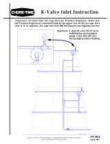
Broiler System Layout
System Layout
Figure 1.(4 House Layout)
Compressor with Holding Tank
PDS
TM
Control
PDS
TM
Control
PDS
TM
Control
PDS
TM
Control
Figure 2.Broiler Layout
1/4" PDS
TM
CONNECTOR TEE
(PART NO. 45894)
1/4" O.D. PDS TUBING
(PART NO. 45895-500)
INLET
INLET
INLET
INLET
INLET
INLET
INLET
INLET
PDS
TM
Control

System Layout Pneumatic Drinking System (PDS) Control
8
MW2467B
Layer System Layout
One Water Line Per Tier, One Regulator Per Tier
Two Water Lines per Tier, Two Regulators Per Tier
Figure 3.One Line/One Regulator
Regulator
nector Tee
o. 45894)
ubing
895)
Figure 4.Two Lines Two Regulators
Regulator
S
TM
Connector Tee
(Part No. 45894)
DS
TM
Tubing
rt No. 45895)


Installation Pneumatic Drinking System (PDS) Control
10
MW2467B
Pressure Sensor location (for 56039-X PDS™ Systems)
There should be one Pressure Sensor installed per PDS™ Control.
The Pressure Sensor should be installed close to a Stand Tube, preferably no more than one Nipple Pipe away.
This will help ensure an accurate reading.
Mounting
Chore-Tronics
®
3 Auto-Adjust PDS™ (56039-X) Control Mounting
Locate the control in a convenient location where it can easily be seen and adjusted.
Fasten the control to the wall through the four holes in the corners with #10 Flat Head Wood Screws. (Not
Supplied).
Installation
(56120)
Pressure Sensor
No more than one Nipple Pipe Section
Figure 6.Pressure Sensor Location
End of 1st Nipple Pipe next
to a Stand tube
Figure 7.Chore-Tronics 3 PDS
TM
Mounting
14-1/8" [35.9 cm]
16-3/4" [42.5 cm]
21-1/8" [53.6 cm]
23-3/4" [60.3 cm]
30-15/16" [78.6 cm]
Mounting Hole Locations

Pneumatic Drinking System (PDS) Control Installation
MW2467B
11
12-40 Station PDS™ (54373-X) Control Mounting
Locate the control in a convenient location where it can easily be seen and adjusted.
Fasten the PDS
TM
Control and the Rain Bird
®
Control to the wall. Use #10 Flat Head Wood Screws. (Not
Supplied) to Mount the boxes using the four holes in the corners as shown.
Connect the PDS
TM
Control and the Rain Bird
®
Control together with liquid tight connectors and conduit (not
supplied), to allow wires to be run between them.
4 and 8 Station (52430-X) PDS™ Control Mounting
Locate the control in a convenient location where it can easily be seen and adjusted.
Fasten the control to the wall through the four holes in the corners with #10 Flat Head Wood Screws. (Not
Supplied)
Figure 8.Chore-Tronics 3 PDS
TM
Mounting
13-1/4" [33.7 cm]
15-5/8" [39.6 cm]
15-1/4" [38.7 cm]
17-5/8" [44.7 cm]
13-1/4" [33.7 cm]
Mounting Hole Locations
Mounting Hole
Locations
4-1/2" [11.4 cm]
27-1/2" [69.9 cm]
Conduit (Not Included)
Conduit Connector
(Not Included)
8-1/2"
[21.6 cm]
12-1/2" [31.8 cm]
13-1/4" [33.7 cm]
15-5/8" [39.6 cm]
31" [78.7 cm]
15-1/4" [38.7 cm]
17-5/8" [44.7 cm]
Figure 9.4 & 8 Station PDS™ Mounting

Installation Pneumatic Drinking System (PDS) Control
12
MW2467B
Air Supply
Caution! DO NOT FLUSH DRINKER LINES WITH PDS™ CONTROL unless drinker lines are pressurized
with water! Damage may occur if this caution is not followed.
Connecting the compressed air supply (All Models)
Air compressor (not supplied) guidelines to operate the system.
• All air compressors must have a minimum rating to run 4 times per hour for 5 minutes each run.
• One (1) PDS™ Control - 2 gallon minimum
recommended air supply tank.
• Two (2) - four (4) PDS™ Controls - 5 gallon minimum recommended air supply tank.
• Five (5) - six (6) PDS™ Controls - 10 gallon minimum recommended air supply tank.
• Air regulator with 1/4" fitting.
• Air /water separator.
Note: The PDS
TM
Control operates between 6 & 12 psi [41.37 kPa & 82.74 kPa]. Most air Regulators sup-
plied with air compressors will not effectively regulate air pressure at this low pressure. Failure to regulate
pressure will result in damage to components.
1.Install an Air Regulator and an Air Separator after the Air Compressor.
2.Connect the air supply to the incoming pressure line on the PDS
TM
control.
3.Verify that the PDS
TM
Control has an Air Pressure reading between 6 & 12
psi [41.37 kPa & 82.74 kPa] (See Figure 10.)
Air supplied to the 52430-X & 54373-X PDS
™
Controls
•BEFORE connecting the compressed air supply to the Control, turn the red adjustment knob clockwise
(Decrease) until the knob stops turning (See Figure 11.)
Figure 10.Pressure Gauge
Figure 11.Adjustment Knob
Adjustment Knob

Pneumatic Drinking System (PDS) Control Installation
MW2467B
13
Tubing
See Figure 3. on page 8 through Figure 5. on page 9 for typical tubing diagrams.
Note: For Versa
®
Plus and Vike
tm
Systems with two pipes per tier Chore-Time recommends two regulators per
station of the PDS control split between two cage rows as shown in Figure 5. to prevent overfill of the drain
when flushing.
Each Station may be used to supply air to two regulators. Controlling
more than 2 regulators per station may overdraw water supply.
1.Remove the Air Station Plugs (See Figure 12.) and attach the
Tubes to the stations.
2.Route the regulator tubing with a drip loop so any condensation in
the air lines will not run into the control. (See Figure 13.)
3.Route the Tubing across the ceiling and down the water supply
hoses that supply the regulators.
4.Connect the Tubing to the air supply connection of the regulators (See Figure 14.).
Note: If not all stations are being used, ensure that the un-used stations are plugged or compressor over
cycling may result.
(55837)
Air Station
Plug
Figure 12.Air Station Plug
Figure 13. Regulator Tube Leads
Drip Loop
Figure 14. Air Supply to Regulator
Air Supply
Connection

Installation Pneumatic Drinking System (PDS) Control
14
MW2467B
Wiring
Chore-Tronics
®
3 Auto-Adjust PDS
™
Control (56039-X) Wiring
Warning: Electric shock can cause severe injury or death. Make sure power supply is turned OFF before
connecting power wires. All electrical connections and wiring runs must be made according to local
building codes.
Note: No backup battery needed! All timer settings are stored indefinitely in memory.
Note: Do Not move Relay Switches to "Manual" or "Auto" for the PDS
TM
Regulator Increase/Decrease until you
have checked all the PDS
TM
Settings and finished the Startup section on page 20.
Figure 15.Chore-Tronics Wiring
1
2
4
3
5
6
7 8
1
2
3
4
5
6
7
8
F to C Board (49815)
ON
12 3 42
(In CT3 Main Box)
(49746) Flat Cable
PDS Control Box
Dip Switches
1 Up
2,3, and 4 Down
Figure 15.56039-X Wiring


Pneumatic Drinking System (PDS) Control Installation
MW2467B
17
4 and 8 Station PDS™ (52430-X) Control to CHORE-TRONICS
®
Warning: Electric shock can cause severe injury or death. Make sure power supply is turned OFF before
connecting power wires. All electrical connections and wiring runs must be made according to local
building codes.
When using CHORE-TRONICS
®
to monitor water consumption, flush water can be omitted from the total. To
do this connect one wire to common and one wire to MV both in the Rain Bird Timer. Run these two wires to a
24VAC Coil Relay (not supplied), from the relay run the two wires to the Chore-Tronics control, (See Figure
18.) Chore-Time has a 3 pole (only one pole is needed), 24 Volt relay available. (Part No. 56577-24)
Internal Wiring
Figure 18. Rain Bird/Chore-Tronics Wiring
Figure 19. 4 and 8 Station Internal Wiring

Installation Pneumatic Drinking System (PDS) Control
18
MW2467B
12-40 Station PDS
™
Control (Part No.54373-X) Wiring
Warning: Electric shock can cause severe injury or death. Make sure power supply is turned OFF before
connecting power wires. All electrical connections and wiring runs must be made according to local
building codes.
RainBird
®
Control Wiring
Connect the power source to the RainBird
®
Control according to the RainBird
®
Control Installation Manual.
Surge Protection and Grounding: The ESP-LXME Controller is equipped with built-in electrical surge
protection. For this system to function, you must properly ground the Controller.
Warning: The ESP-LXME Controller must be properly surge protected and grounded. Failure to do so
could result in failure of the Controller and voiding the warranty.
Connect Power Source: The ESP-LXME Controller has an internal transformer that reduces supply voltage
(120 VAC in U.S. models; 230 VAC in international models to 24 VAC. You will need to connect power supply
wires to the transformer’s three wires. (Line, Neutral, Ground)
RainBird
®
Control to PDS
™
Control Wiring
The RainBird
®
Modules are connected to the Terminal Strip in the PDS
TM
Control by wires (18AWG minimum)
routed through the connecting conduit (Not Supplied) (See Figure 20.) Connect each Module in turn to the
appropriate terminal in the PDS
TM
Control. Number 1 on the first RainBird
®
Module will be connected to the
number 1 on the PDS
TM
Control. This will be repeated until all the module terminals are connected to the PDS
TM
Terminals.
Note: "Valve" in the RainBird
®
Manual is the "Solenoid Connection" in the PDS
TM
Control.
Incoming Air Pressure
Water Column Pressure
Regulator Air Pressure
Connecting Conduit
(Not Supplied)
Common Wire Connections
Module
Figure 20.RainBird
®
Control to PDS
TM
Wiring

Pneumatic Drinking System (PDS) Control Installation
MW2467B
19
Connection to Chore-Tronics
®
When using Chore-Tronics
®
to monitor water consumption, flush water can be omitted from the total. To do this
connect one wire to common and one wire to MV both in the Rain Bird
®
Control. Run these two wires to a
24VAC Coil Relay (not supplied), from the relay run the two wires to the Chore-Tronics
®
Control, (See Figure
21.). Chore-Time has a 3 pole (only one pole is needed), 24 Volt relay available. (Part No. 56577-24)
Figure 21.RainBird
®
to ChoreTronics
®
Wiring

Start Up Pneumatic Drinking System (PDS) Control
20
MW2467B
Step 1: Charging the Lines
Caution: DO NOT FLUSH DRINKER LINES WITH PDS™ CONTROL unless drinker
lines are filled with water! Damage may occur if this caution is not followed.
Before compressed air is connected to the Regulator, the drinker lines should be charged with water. This can be
done by turning the selector knob on each Regulator to the "ON" position.
Step 2: Water Column Gauge Calibration
(52430-X, & 54373-X PDS Control Models)
•Using the PDS Control Adjustment Knob (See Figure 11. on page 12), bring the line to 14" water col-
umn as measured at regulator stand tube.
•Pop off plastic cover and turn calibration screw till arrow points to 14" (See Figure 22.). Re-attach
Cover.
•Chore-Time recommends to verify calibration after
each flock.
Step 3: Air Leak Test
Check each PDS control for air leaks with the water column gauge at 14 inches [35.6 cm].
To check for air leaks:
•Pinch the incoming air supply tube to shut off the incoming air pressure.
•Watch the air pressure gauge on the control (See Figure 22.). The gauge should not drop any more than
2 psi [13.79 kPa] in 1 minute.
•If the air pressure does drop faster than 2 psi [13.79 kPa] in 1 minute, refer to the “TroubleShooting”
on page 27.
Step 4: Setting the Regulators Drinker Line Minimum Water Column
1.Disconnect the Main Air Hose from the air com-
pressor.
2.Turn on the water to the drinker lines.
3.Adjust each Regulator to the water column
minimum you want.
4.Re-connect the main air hose.
Start Up
Figure 22. Water Column Gauge
Calibration
Screw
Adjustment Knob
Figure 23.Regulator Adjustment
/