Page is loading ...

Designed by Installers for Installers
INSTALLATION GUIDE
DB3
2016 Volkswagen Golf (Smart Key) - 403.VW06 1.27 RSR
© 2017 Directed, Vista CA
This product is intended for installation by a professional installer only! Attempts to install this
product by a person other than a trained professional may result in severe damage to a vehicle’s
electrical system and components.

Introduction 4
Pre-installation and application warnings 5
Wiring diagram 6
Locating components in the vehicle 7
Immobilizer interface with OEM immobilizer receiver 8
Vehicle connections 10
SmartStart/XL202 installation notes 12
Connecting the module 13
Module programming 14
LED diagnostics and troubleshooting 15
Parking light error codes 17
Soft reset 18
Hard reset 19
Feature programming 20
Feature and option list 21
Limited one year consumer warranty 22
Quick reference guide 23
Contents

3 403.VW06 1.27 2016 Volkswagen Golf (Smart Key)
© 2017-02-08 Directed. All rights reserved.
Warning! Safety first
The following safety warnings must be observed at all times:
• Due to the complexity of this system, installation of this product must only be performed by an authorized Directed dealer.
• When properly installed, this system can start the vehicle via a command signal from the remote control. Therefore, never
operate the system in an area that does not have adequate ventilation.
The following precautions are the sole responsibility of the user; however, authorized Directed dealers should:
• Never use a test light or logic probe when installing this unit. Always use a multimeter.
• Never operate the system in an enclosed or partially enclosed area without ventilation (such as a garage).
• When parking in an enclosed or partially enclosed area or when having the vehicle serviced, the remote start system must
be disabled using the installed toggle switch. It is the user’s sole responsibility to properly handle and keep out of reach from
children all remote controls to assure that the system does not unintentionally remote start the vehicle.
• USER MUST INSTALL A CARBON MONOXIDE DETECTOR IN OR ABOUT THE LIVING AREA ADJACENT TO THE VEHICLE.
ALL DOORS LEADING FROM ADJACENT LIVING AREAS TO THE ENCLOSED OR PARTIALLY ENCLOSED VEHICLE
STORAGE AREA MUST REMAIN CLOSED AT ALL TIMES.
Use of this product in a manner contrary to its intended mode of operation may result in property damage, personal injury, or
death. Except when performing the Safety Check outlined in this installation guide, (1) Never remotely start the vehicle with
the vehicle in gear, and (2) Never remotely start the vehicle with the keys in the ignition. The user is responsible for having the
neutral safety feature of the vehicle periodically checked, wherein the vehicle must not remotely start while the car is in gear.
This testing should be performed by an authorized Directed dealer in accordance with the Safety Check outlined in this product
installation guide. If the vehicle starts in gear, cease remote start operation immediately and consult with the user to fix the problem
immediately.
OPERATION OF THE REMOTE START MODULE IF THE VEHICLE STARTS IN GEAR IS CONTRARY TO ITS INTENDED MODE OF
OPERATION. OPERATING THE REMOTE START SYSTEM UNDER THESE CONDITIONS MAY RESULT IN PROPERTY DAMAGE
OR PERSONAL INJURY. IMMEDIATELY CEASE THE USE OF THE UNIT AND REPAIR OR DISCONNECT THE INSTALLED REMOTE
START MODULE. DIRECTED WILL NOT BE HELD RESPONSIBLE OR PAY FOR INSTALLATION OR REINSTALLATION COSTS.
Remote starters for manual transmission pose significant risks if not properly installed and operated. When testing to ensure the
installation is working properly, only remote start the vehicle in neutral gear, on a flat surface and with a functional, fully engaged
parking brake. Do not allow anyone to stand in front of or behind the vehicle.
This product should not be installed in any convertible vehicles, soft or hard top with a manual transmission. Installation in such
vehicles may pose certain risk.

4 403.VW06 1.27 2016 Volkswagen Golf (Smart Key)
© 2017-02-08 Directed. All rights reserved.
Introduction
DB3 is an all-in-one door lock and override module. This guide supports the installation of a DB3 in Remote
Start Ready (RSR) mode. This solution offers three (3) configuration options to control your system: 3x OEM Lock
Remote Start Activation, RF System or SmartStart (all sold separately).
Warning!
This solution is compatible with the 2016 Volkswagen Golf (Smart Key) and offers the following features:
• AV-Parking Lights Control
• DL-Arm Factory Security
• DL-Disarm Factory Security
• DL-Door Lock Control
• DL-Door Unlock
• DL-Driver Priority Unlock
• DL-Trunk / Hatch Release
• FOB-Control of aftermarket alarm with OEM remote
• PK-Universal RF Bypass- Key Req'd
• RS-3x LOCK START (Start control using OEM Remote)
• RS-3x LOCK STOP (Stop control using OEM Remote)
• RS-RAP Shut Down (Retained ACC Power)
• RS-Remote Start Ready
• RS-SmartStart
• RS-Tach / RPM Output
• SS-Entry Monitoring ALL Door Pins
• SS-Entry Monitoring Hood Pin
• SS-Entry Monitoring Trunk/Hatch Pin
• SS-Factory Alarm Trigger Monitoring
• ST-Brake Status (foot brake)
• ST-Door Locks Status
• ST-E-Brake Status
• ST-Ignition Status
This module can only be flashed and configured using DirectLink at www.directechs.com or using the Directechs
Mobile application for smartphones. Refer to “Connecting the module” for more information.

5 403.VW06 1.27 2016 Volkswagen Golf (Smart Key)
© 2017-02-08 Directed. All rights reserved.
Pre-installation and application warnings
Firmware notes: This section highlights important information for this specific firmware and will assist in
pricing accordingly, as well as bringing awareness to any operational or vehicle limitations.
T-Harness
compatible
Keys required for
programming
1
Keys required for
operation
1
Important! RSR installations are NOT compatible with vehicles equipped with a manual transmission.
Remote Start Ready (RSR) is a function that enables the interface module to remote start the vehicle completely on its own.
Consequently, there is no need for an aftermarket or an OEM remote starter in order to start the vehicle from a distance.
SmartStart Compatible: SmartStart is equipped with D2D, which means it can be connected to an interface module and
used in Remote Start Ready (RSR) mode without the use of a remote starter. See "Module programming" for more information.
Unless specified otherwise, all connectors are displayed from the wire side, with the exception of the OBDII diagnostic
connector.
Important! This firmware does NOT support Immobilizer bypass. One (1) programmed OEM key must be wired into the
vehicle to complete the installation of a remote starter.
Refer to "Vehicle connections" following the wiring diagram.
General notes: This section highlights important information for this specific firmware.
[1] For Key Wrap instructions, refer to "Immobilizer interface with OEM immobilizer receiver".
Additional parts required (maximum required):
Diode 6A
0 x 1A Diode
86 85
30
87a
87
0 x Relay
Resistor 100Ω
0 x Resistor
Fuse 7.5A
0 x Fuse

6 403.VW06 1.27 2016 Volkswagen Golf (Smart Key)
© 2017-02-08 Directed. All rights reserved.
Important!
The Hood Pin and Remote Start Safety Override Switch are mandatory safety devices, but are NOT supplied with the DBALL.
1
13 38
63
(-) PTS 1 Output: Green/Black: 2
(+) Brake Output: Gray: 6
(-) PTS 2 Output: Violet/Brown: 9
HS CAN 1 High: Tan/Black: 3
HS CAN 1 Low: Tan: 4
[1] Key Wrap: Brown/Red: 12
[1] Key Wrap: Yellow/Red: 11
[1] Key Wrap: Orange/Red: 10
HS CAN 2 High: Orange/Green: 5
HS CAN 2 Low: Orange/Brown: 6
(+) 12V: Red: 13
(-) Ground: Black: 14
(+) Brake:
Black/Red,
pin 58
8
16
OBDII Diagnostic Connector
1
9
HS CAN 1 High:
Orange/Red, pin 6
HS CAN 1 Low:
Orange/Brown, pin 14
1
9
2
10
3
11
4
12
5
13
6
14
7
15
8
16
(-) PTS 1: Violet, pin 4
(-) PTS 2: Violet/Blue, pin 13
HS CAN 2 High:
Orange/Green,
pin 16
HS CAN 2 Low:
Orange/Brown,
pin 15
(+) 12V:Red/White or
Red/Gray, pin 1
A1
A2
A3
(+) Parking Light:
Gray/Yellow, pin 8
1 2 4 5
6 7 9 10
3
8
Parking Light Interrupt:
Red/White, pin 3
CUT
(+) Parking Light Output: Brown: 7
Parking Light Interrupt (vehicle side): Yellow: 8
Parking Light Interrupt (conn. side): Orange/Yellow: 9
Electronic Steering
Column Module
(black 16-pin under column)
Headlight Switch
(red 10-pin connector)
Wiring diagram
Hood Pin
Remote Start Safety
Override Switch
6: White/Black: (-) Hood Input
Note: hood pin only required on
vehicles not equipped with a
factory hood pin.
You can connect to either
a XL202 RFTD OR a
SmartStart module.
Refer to the
SmartStart/XL202
Installation Notes for
more information.

7 403.VW06 1.27 2016 Volkswagen Golf (Smart Key)
© 2017-02-08 Directed. All rights reserved.
VESCM - Vehicle Electrical System Control Module
at Driver Side under dash, above Driver Kick Panel
ESCLCM - Electronic Steering Column
Lock Control Module
at Steering Column
A2
A3
A1
Locating components in the vehicle

8 403.VW06 1.27 2016 Volkswagen Golf (Smart Key)
© 2017-02-08 Directed. All rights reserved.
NOTE:
- Your OEM remote may differ from the model shown in the illustrations.
- Remove Battery from OEM FOB prior to performing the Key Wrap.
- Make 4-6 loops and place them around the front of the plastic body of the vehicle's coded key as shown above.
- Test and secure mounted loop before reassembling the vehicle.
Note: OEM immobilizer receiver is located
on the underside of the steering column,
where the ignition switch would normally be.
IMPORTANT!: Not all OEM keys can be inserted in 556U because of their size.
Make sure the key will fit, otherwise it is recommended to use a different method.
10
DBALL2
RF
Prog. Button
LED
4
14 12
2
Note: OEM immobilizer receiver is located
on the underside of the steering column,
where the ignition switch would normally be.
Relay N.O.: Brown/Red: 12
Relay Common: Yellow/Red: 11
OEM
Immobilizer
Receiver
10
DBALL2
RF
Prog. Button
LED
4
14 12
2
NO Relay 2: Brown/Red: 12
Common Relay 2: Yellow/Red: 11
4-6 loops
Remove battery from
OEM Remote Control
556U or 556UW is sold SEPARATELY.
OEM
Immobilizer
Receiver
PIN 5 Violet
PIN 1 Red
PIN 6 Green
PIN 4 Black
PIN 2 Blue
PIN 3 Violet
(+) 12V
OEM Valet Key
Method 1: Immobilizer interface with OEM immobilizer receiver (PTS)
Method 2: Immobilizer interface with 556U (PTS)

9 403.VW06 1.27 2016 Volkswagen Golf (Smart Key)
© 2017-02-08 Directed. All rights reserved.
OEM
Immobilizer
Receiver
10
DBALL2
RF
Prog. Button
LED
4
14 12
2
NO Relay 2: Brown/Red: 12
Common Relay 2: Yellow/Red: 11
NC Relay 2: Orange/Red: 10
Immobilizer ECU
4-6 loops
Note: OEM immobilizer receiver is located
on the underside of the steering column,
where the ignition switch would normally be.
Remove battery from
OEM Remote Control
- Make 4-6 loops and place the around the front of the plastic body of the vehicle’s coded key as
shown above.
- Connect with OEM Immobilier Ring as shown in the above diagram.
- When possible, use valet key for key wrap. if blade key is used, battery must be removed.
Method 3: Key wrap for Push-to-Start (PTS) using OEM immobilizer ring

10 403.VW06 1.27 2016 Volkswagen Golf (Smart Key)
© 2017-02-08 Directed. All rights reserved.
Vehicle connections
The connection information listed below is specific to the 2016 Volkswagen Golf (Smart Key). Refer to “Pre-installation and application warnings” for a list of important notes.
Data 14-pin blue connector (H1)
Module Connects To
Conn./Pin Color Description Wire Location (+/-) Wire Color Ref.
H1/1 Light Green (DATA) No Connection
H1/2 Violet/Yellow (DATA) No Connection
H1/3 Tan/Black (DATA) HS CAN High
H1/4 Tan (DATA) HS CAN Low
H1/5 Orange/Green (DATA) HS CAN High
H1/6 Orange/Brown (DATA) HS CAN Low
H1/7 Brown Relay N.O. Pk Light Output
H1/8 Yellow Relay COM Pk Light Output
H1/9 Orange or Orange/Yellow Relay N.C. Pk Light Output
H1/10 Orange/Red Relay N.C. Key Wrap
H1/11 Yellow/Red Relay COM Key Wrap
H1/12 Brown/Red Relay N.O. Key Wrap
H1/13 Red (+) 12 Volt
H1/14 Black (-) Ground
Output 12-pin red connector (H2)
Module Connects To
Conn./Pin Color Description Wire Location (+/-) Wire Color Ref.
H2/1 Black/White (-) Hazard Light Output
H2/2 Green/Black
(-) PTS
[4]
H2/3 Green/White (-) No Connection
H2/4 Red/Black (-) Trunk Output
H2/5 Violet/White (AC) No Connection
H2/6 Gray (+) Brake Output
H2/7 Gray/Black (+) No Connection
H2/8 Violet/Green (MUX) No Connection
H2/9 Violet/Brown (MUX) PTS
H2/10 Yellow/Black No Connection
H2/11 Orange/Black No Connection
H2/12 Blue/Red (-) No Connection

11 403.VW06 1.27 2016 Volkswagen Golf (Smart Key)
© 2017-02-08 Directed. All rights reserved.
Input 10-pin black connector (H3)
Module Connects To
Conn./Pin Color Description Wire Location (+/-) Wire Color Ref.
H3/1 Black/White (-) No Connection
H3/2 Green/Black (-) No Connection
H3/3 Green/White
(-)
[2]
No Connection
H3/4 Red/Black (-) No Connection
H3/5 Violet/White
(-)
[3]
No Connection
H3/6 Gray (-) Hood Switch Input
H3/7 Gray/Black (+) No Connection
H3/8 Violet/Green (+) No Connection
H3/9 Violet/Brown (+) No Connection
H3/10 Yellow/Black (-) No Connection
D2D 4-pin white connector (H4)
Module
Conn./Pin Color Description
H4/1 Green (Data) TX
H4/2 Black (-) Ground
H4/3 Blue (Data) RX
H4/4 Red (+) 12 Volt
RF 2-pin white connector (H5)
Module
Conn./Pin Color Description
H5/1 N/A
H5/2 N/A

12 403.VW06 1.27 2016 Volkswagen Golf (Smart Key)
© 2017-02-08 Directed. All rights reserved.
SmartStart/XL202 installation notes
The DB3 Remote Start Ready (RSR) solution offers three (3) configuration options to control your system: 3x OEM Lock Remote
Start Activation, RF Kit or SmartStart (both sold separately). This section provides specific installation information for SmartStart and
XL202.
SmartStart revision A
SmartStart is optional and not included. It MUST be purchased separately.
SmarStart
Cable
D2D (4 pins, white)
4 pins
2 pins,
not used
Configuration wires (White & Brown or Blue)
Cut Brown or Blue loop
1412
10
42
SmarStart
Cable
D2D (4 pins, white)
4 pins
2 pins,
not used
Configuration wires (Gray & White)
Connect Gray wire to (-) Ground
1412
10
42
5 pins
THIS SIDE UP
D2D
XOVER Cable
1412
10
42
SmartStart revision B
SmartStart is optional and not included. It MUST be purchased separately.
SmarStart
Cable
D2D (4 pins, white)
4 pins
2 pins,
not used
Configuration wires (White & Brown or Blue)
Cut Brown or Blue loop
1412
10
42
SmarStart
Cable
D2D (4 pins, white)
4 pins
2 pins,
not used
Configuration wires (Gray & White)
Connect Gray wire to (-) Ground
1412
10
42
5 pins
THIS SIDE UP
D2D
XOVER Cable
1412
10
42
RF System
The optional XL202 and antenna are not included and MUST be purchased separately.
SmarStart
Cable
D2D (4 pins, white)
4 pins
2 pins,
not used
Configuration wires (White & Brown or Blue)
Cut Brown or Blue loop
1412
10
42
SmarStart
Cable
D2D (4 pins, white)
4 pins
2 pins,
not used
Configuration wires (Gray & White)
Connect Gray wire to (-) Ground
1412
10
42
5 pins
THIS SIDE UP
D2D
XOVER Cable
1412
10
42
RF System & PKE combination
Refer to the Passive Keyless Entry (PKE) Installation Guide (N2102T) for detailed wiring information.
RF System, PKE & SmartStart BT combination
Refer to the Passive Keyless Entry (PKE) Installation Guide (N2102T) for detailed wiring information.
The modules must be connected in a specific order. Refer to “Module programming” for more information.
1. Use the D2D Crossover (XOVER) cable that is provided with XL202, and NOT the one in the DB3 package.
2. The modules must be connected in a specific order. Refer to “Module programming” for more information.
The modules must be connected in a specific order. Refer to “Module programming” for more information.

13 403.VW06 1.27 2016 Volkswagen Golf (Smart Key)
© 2017-02-08 Directed. All rights reserved.
Connecting the module
Important!
Make all the required connections to the vehicle, as described in this guide, and double check to ensure everything is correct prior
to moving onto programming.
Note: Before connecting either the XL202 or SmartStart module to DB3, it is important to ensure that the proper feature and
function programming is selected using DirectLink (version 4.5 or higher). Visit www.directechs.com to download the latest version
of the application.
Warning! To take advantage of advanced features, you must use DirectLink 4.5 (and higher) or the Directechs Mobile application.
Flashing a module using your computer:
1. Connect the interface module to your computer using the XKLoader2.
2. Go to www.directechs.com using Internet Explorer, and select the Flash Module button.
3. Follow the instructions to select your vehicle, installation type, and configure your options.
4. Once you have configured the firmware options, click on the FLASH button.
Flashing a module using your smartphone or tablet:
1. Connect the interface module to your XKLoader3.
2. Launch the Directechs Mobile app on your smartphone or tablet.
3. Select FLASH YOUR MODULE and follow the on screen instructions.
When the flashing operation is successful, you can proceed with the instructions below.
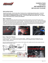
SmartStart installation
The DB3 module must be disconnected from any power source before SmartStart can
be connected to it. Failing to do so could damage DB3.
1. To ensure that the D2D communication between SmartStart and DB3 works properly,
connect the Gray wire to a ground source (Rev B SmartStart), and cut the Brown or
Blue loop (Rev A SmartStart).
2. Do NOT connect the 2-pin harness (on SmartStart). Power and ground will be
provided by the DB3 D2D connector.
3. Connect SmartStart to DB3 using the D2D port.
D2D
D2D
OR
XL202 installation
Connect XL202 to DB3 using the D2D port.
D2D
D2D

14 403.VW06 1.27 2016 Volkswagen Golf (Smart Key)
© 2017-02-08 Directed. All rights reserved.
Module programming
Refer to “LED diagnostics and troubleshooting” for more information and for troubleshooting purposes.
1
Connect the 10-pin, 12-pin and 14-pin harnesses to DB3, then wait until the LED turns
ON solid red.
2
Press the Push-to-Start (PTS) button once to turn the ignition ON. The LED flashes
orange, then flashes green.
3
The LED turns ON solid green for 3 seconds, then turns OFF.Press the PTS button
once more to turn the ignition OFF.
You have successfully completed the module programming sequence.

15 403.VW06 1.27 2016 Volkswagen Golf (Smart Key)
© 2017-02-08 Directed. All rights reserved.
LED diagnostics and troubleshooting
This section provides LED diagnostics and troubleshooting information to guide you through the various stages of your installation.
Module Programming
LED Description Troubleshooting
Off
Module has no power.
Make sure the D2D harness is connected and that 12 Volt is present between the red and black
wires. If 12 Volt is present, the module may be defective.
Solid red
Waiting to begin the programming
sequence.
Ensure the correct programming procedure is being followed.
Flashes green &
red
Initialization failed.
Reset the module and complete the programming again. If the issue persists, please contact
Technical Support.
Solid orange
Transponder functions were skipped.
(If compatible) when RXT mode is not desired or convenience features are needed, please reset
the and reprogram the module.
Flashes green
All required CAN networks has been
detected.
Normal operation.
Flashes orange
1 of 2 CAN networks has been detected. Normal operation.
Flashes orange
slowly
Key2GO initiated.
Please follow the steps indicated in “Module programming” to complete the Key2GO
programming.
Solid green x 3
secs
Module was successfully programmed
with all functions.
Normal operation.
Solid orange x 3
secs
Module was successfully programmed
without transponder functions.
Normal operation.
Module Programming - Error codes
LED Description Troubleshooting
Flashes red x 1
CAN2 not detected.
Check the CAN2 Orange/Green and Orange/Brown wire connections. Wake up the data bus
by turning the ignition on and try again. If your installation does not require this connection, skip
this step by pressing the programming button 5 times.
Flashes red x 1
J1850 not detected.
Check the J1850 wire connection. Wake up the data bus by turning the ignition on and try
again.
Flashes red x 2
CAN1 not detected.
Check the CAN1 Tan and Tan/Black wire connections. Wake up the data bus by turning the
ignition on and try again. If your installation does not require this connection, skip this step by
pressing the programming button 5 times.
Flashes red x 3
Bypass data not detected.
Check the bypass line connection. If more than one wire is used, make sure they are not inverted.
Ensure the vehicle still operates correctly using the factory key.
Flashes red x 4
Bypass processing error.
The bypass calculation failed. Reset the module and try again. If the condition persists, please
contact Technical Support.
Flashes red x 5
ISO 1 not detected.
The Yellow/Black wire did not detect the expected signal. Refer to “Installation (wiring diagrams
& vehicle wiring reference charts)” on page “Installation (wiring diagrams & vehicle wiring
reference charts)” to check the connections.
Flashes red x 6
ISO 2 not detected.
The Orange/Black wire did not detect the expected signal. Refer to “Installation (wiring diagrams
& vehicle wiring reference charts)” to check the connections.
Flashes red x 7
MUX not detected.
The Violet/Green or Violet/Brown wire did not detect the expected voltage value. Refer to
“Installation (wiring diagrams & vehicle wiring reference charts)” to check the connections.
External Module Synchronization
LED Description Troubleshooting
(Flashes red, red,
then orange) x 10
OBDII feature not supported. The diagnostic data bus was not detected, therefore the SmartStart features will be limited.

16 403.VW06 1.27 2016 Volkswagen Golf (Smart Key)
© 2017-02-08 Directed. All rights reserved.
Active Ground When Running (Status)
LED Description Troubleshooting
Flashes green
Ground When Running (Status) command
received.
The module has initialized the remote start sequence.
Flashes red &
orange
Ignition ON command received. The module has received the Ignition ON command and is processing the remote start sequence.
Flashes green
quickly
Start ON command received. The module has received the Start ON command and is processing the remote start sequence.
Flashes red x 10
PTS shutdown error. The PTS output from the module was not activated due to safety protection.
Flashes red x 21
CAN bus incorrectly detected.
Verify the CAN1 and CAN2 connections. Refer to “Installation (wiring diagrams & vehicle wiring
reference charts)” to check the connections.
Commands
LED Description Troubleshooting
Flashes orange x 1
LOCK command received.
If the bypass module fails to flash, it did not receive the signal. Commands can come from RF or
D2D.
Flashes orange x 2
UNLOCK command received.
If the bypass module fails to flash, it did not receive the signal. Commands can come from RF or
D2D.
Flashes orange x 3
TRUNK command received.
If the bypass module fails to flash, it did not receive the signal. Commands can come from RF or
D2D.
Flashes orange x 4
AUX1 command received.
If the bypass module fails to flash, it did not receive the signal. Commands can come from RF or
D2D.
Flashes orange x 5
AUX2 command received.
If the bypass module fails to flash, it did not receive the signal. Commands can come from RF or
D2D.
Flashes orange x 6
AUX3 command received.
If the bypass module fails to flash, it did not receive the signal. Commands can come from RF or
D2D.
Shutdown Codes
LED Description Troubleshooting
Flashes green x 1
Takeover successful. Normal operation.
Flashes red x 1
Runsafe was not disabled.
No UNLOCK command was received prior to opening the door, or the 45 second timer expired
in takeover mode.
Flashes red x 2
Brake was not detected. The brakes were not detected, which prevents the system from shutting down the vehicle.
Flashes red x 3
Smart key was not detected. The smart key was not detected, which prevents the system from shutting down the vehicle.
Flashes red x 4
Speed was detected. The vehicle was detected as moving, which prevents the system from shutting it down.
RSR Error Codes
LED Description Troubleshooting
Flashes red x 7
RFTD disabled.
3x OEM Lock Remote Start Activation was attempted when the RFTD feature is disabled. Make
sure 3x Lock Start is selected from the web in the flashing process.
Flashes red x 9
Feature error. An RSR feature file mismatch was detected. Please contact Technical Support.

17 403.VW06 1.27 2016 Volkswagen Golf (Smart Key)
© 2017-02-08 Directed. All rights reserved.
Parking light error codes
The parking lights on your vehicle will flash a specific number of times 3 seconds following an unscheduled shutdown. Each
flashing pattern is described below.
Flashes Diagnostic
1 Runtime expired.
2 Over-rev shutdown.
3 Low or no RPM.
4 Shutdown without remote.
5 Brake shutdown.
6 Hood shutdown/Remote start safety override switch is ON.*
7 Remote start safety override switch is ON.*
* If the vehicle hood status is supported through data, the safety override switch input will report 7 flashes.

18 403.VW06 1.27 2016 Volkswagen Golf (Smart Key)
© 2017-02-08 Directed. All rights reserved.
Soft reset
1
Connect the 10-pin & 12-pin harnesses to the module. Press and hold the
programming button, then connect the 14-pin harness to the module.
4
th
(14-pin)
3
rd
(Button)
1
st
(10-pin)
2
nd
(12-pin)
2
Wait 3 seconds until the LED turns ON solid orange then release the programming button.
The LED turns ON solid red.
&&
Solid SolidRelease
A module reset will only erase the steps perfomed in “Module programming”. The firmware and settings flashed to the module
will not be affected.

19 403.VW06 1.27 2016 Volkswagen Golf (Smart Key)
© 2017-02-08 Directed. All rights reserved.
Hard reset
Warning Against Executing a Hard Reset!
1
Connect the 10-pin & 12-pin harnesses to the module. Press and hold the
programming button, then connect the 14-pin harness to the module.
4
th
(14-pin)
3
rd
(Button)
1
st
(10-pin)
2
nd
(12-pin)
2
Wait 3 seconds until the LED turns ON solid orange, and wait 10 more seconds until the
LED starts to flash orange and red.
Solid Flashes
&
3
Release the programming button. The LED turns ON solid red.
&
Release Solid
A hard reset will revert the flashed firmware back to its default factory settings. Depending on the installation, some settings (such
as RFTD and D2D options) may have to be reconfigured. Refer to “Feature and option list”.

20 403.VW06 1.27 2016 Volkswagen Golf (Smart Key)
© 2017-02-08 Directed. All rights reserved.
Feature programming
To enter feature programming routine:
1. Turn the ignition ON, then OFF.
2. Within 5 seconds, press and hold the programming button until the LED turns ON orange (after 3 seconds).
3. Release the Programming button.
4. The LED will flash green once slowly to indicate the feature number is 1. After a short delay, the LED flashes red rapidly to
indicate the current option of feature 1 (e.g. 1 x green followed by 1 x red indicates feature 1 is set to option 1). The flashing
sequence will repeat until a new command is entered.
Changing feature options:
1. Press the lock/arm or unlock/disarm button on aftermarket transmitter to change the option of the selected feature. When
installing the DB3 in RSR using 3x OEM Lock Remote Start Activation only, there is no aftermarket transmitter on which to press
lock/unlock to change the options of the selected feature. Tapping the green or blue lock/unlock wires on the black 10-pin
harness to ground will change the option for the selected feature.
2. The LED flashes red rapidly the number of times equal to the current option number. After a short delay, the LED flashes green
slowly the number of times to indicate the current feature. The flashing sequence will repeat until a new command is entered.
Accessing another feature:
1. Press and release the programming button a number of times to advance from the current feature to the next desired feature.
2. The LED flashes green slowly the number of times equal to the feature number. After a short delay, the LED flashes red rapidly
to indicate the current option of the current feature. The flashing sequence will repeat until a new command is entered.
When the maximum number of features or options is reached, the LED will start flashing again from the first feature or option.
Exiting feature programming:
To exit feature programming, press and hold the programming button for 3 seconds or ensure there is no activity on the interface
for 30 seconds. The LED will turn ON orange for 2 seconds to confirm the end of the programming sequence.
/