
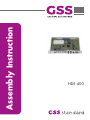
Assembly Instruction
HDE 400

- 2 - HDE 400
Contents
1 Safety regulations and notes ........................................................................4
2 General information ....................................................................................5
2.1 Packing contents ............................................................................5
2.2 Meaning of the symbols used ..........................................................5
2.3 Technical data ...............................................................................5
2.4 Description ...................................................................................7
Signal runtime ...............................................................................8
Software versions ..........................................................................9
Block diagram ...............................................................................9
3 Assembly ..................................................................................................10
3.1 Installing the cassette....................................................................10
3.2 EMC regulations ..........................................................................11
3.3 Cassette overview........................................................................12
3.4 Connecting the cassette ................................................................12
3.5 Updating the software ..................................................................13
4 The control panel at a glance .....................................................................14
4.1 Menu items .................................................................................14
4.2 Control panel ..............................................................................14
5 Programming ............................................................................................15
5.1 Programming procedure ...............................................................15
5.2 Programming the cassette .............................................................18
Selecting the cassette ...................................................................18
Encoder......................................................................................19
Service ID (SID) ......................................................................19
Programme name ...................................................................19
Total data rate ........................................................................20
HDMI Video Format ................................................................20
Video signal type/input ...........................................................21
Group of Picture – GoP ...........................................................21
Audio input / Audio level ........................................................22
Audio data rate ......................................................................23
RF output ....................................................................................23
Deactivate the RF output ..........................................................23
Kind of modulation .................................................................24
RF output level ........................................................................24
Channel / Frequency ..............................................................25
Output symbol rate, QAM modulation
.......................................26
COFDM parameters ...............................................................27

- 3 - HDE 400
COFDM output signal
...............................................................30
Transmission parameters .........................................................31
Transmitter identification ..........................................................32
Substitute signal in the case of an incorrect input signal ...............33
Ethernet parameters .....................................................................33
IP address of the cassette .........................................................34
Address range (subnet mask) ...................................................34
Address of the gateway ..........................................................35
UDP port ...............................................................................35
IP output signal ............................................................................36
Setting the output data rate ......................................................36
Transmission protocol / Port number .........................................37
Quantity of data packets .........................................................38
Forward error correction / Transmission channel .......................38
Output IP address (Multicast/Unicast) ........................................39
Target MAC address (only Unicast) ...........................................39
ASI output ...................................................................................40
ASI transfer rate .....................................................................40
ASI options ............................................................................41
ASI Input station filter; Bypass ASI => RF ........................................42
Output data rate ..........................................................................44
Transport stream ID and ORGNET ID .............................................45
Network Information Table (NIT) ....................................................45
Factory reset / Soft reset ..............................................................46
Factory reset ..........................................................................46
Soft reset ...............................................................................47
Saving settings ...........................................................................47
6 Final procedures ........................................................................................48
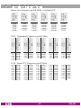
7 Channel and frequency tables ....................................................................49

- 4 - HDE 400
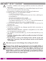
1 safety regulations and notes
• Assembly, installation and servicing should be carried out by authorised
electricians.
• Switch off the operating voltage of the system before beginning with assem-
bly or service work or pull out the mains plug.
• Do not perform installation and service work during thunderstorms.
• Install the system so it will not be able to vibrate…
- in a dust-free, dry environment
- in such a manner that it is protected from moisture, fumes, splashing wa-
ter and dampness
- somewhere protected from direct sunlight
- not within the immediate vicinity of heat sources
- in an ambient temperature of 0 °C to +50 °C. In case of the formation of
condensation wait until the system is completely dried.
• Ensure that the head-end station is adequately ventilated. Do not cover the
ventilation slots.
• Beware of short circuits
• No liability is accepted for any damage caused by faulty connections or
inappropriate handling.
• Observe the relevant standards, regulations and guidelines on the installa-
tion and operation of antenna systems.
• The standards EN/DIN EN 50083 resp. IEC/EN/DIN EN 60728 must be
observed.
• For further information please read the assembly instructions for the head-
end station used.
• Test the software versions of the head-end station and the cassette and
update them if necessary. The current software versions can be found at
"www.mygss.eu".
Take action to prevent static discharge when working on the device!
Electronic devices should never be disposed of in the household rubbish. In
accordance with directive 2002/96/EC of the European Parliament and the
European Council from January 27, 2003 which addresses old electronic and
electrical devices, such devices must be disposed of at a designated collection
facility. At the end of its service life, please take your device to one of these
public collection facilities for proper disposal.

- 5 - HDE 400
2 general information
2.1 PaCking Contents
1 Cassette HDE 400
1 Brief assembly instructions
2.2 meaning of the symbols used
Important note
—> General note
• Performing works
2.3 teChniCal data
The devices meet the following EU directives:
2011/65/EU, 2014/30/EU, 2014/35/EU
The product fulfils the guidelines and standards for CE labelling (page 50).
Unless otherwise noted all values are specified as "typical".
HDMI Input
Tested Video Formats .............1920x1080p24/i50/p50/i60, 1280x720p50/p60,
720x576i50/p50, 720x480i59/p59
Supported Audio Formats ....................................................... Linear PCM
Component Video Input
Input level ..............................................................Y 1 V
ss,
Pb/Pr 0,7 V
pp
Input impedance .............................................................................75 Ω
Tested Video Formats ......... 1920x1080i50, 1280x720p50, 720x576p50,
720x480p59
Supported standards ..........................................................................PAL
CVBS Video Input
Input level ......................................................................................1 V
pp
Input impedance .............................................................................75 Ω
Frequency range ........................................................... 20 Hz … 5 MHz
Supported standards .................................................................... PAL BG
Audio Input
Input level ...............................................................................500 mV
rms
Frequency range ...........................................................20 Hz … 15 kHz

- 6 - HDE 400
MPEG4 Encoder
Transport stream ....................................H.264/AVC High Profile Level 4.0
Setting range of total data rate (video + audio + tables) ........... 1 Mbit/s…30 Mbit/s
Video data rate:
1920x1080p .......................................................... 6 Mbit/s…30 Mbit/s
1920x1080i ........................................................... 6 Mbit/s…24 Mbit/s
1280x720p ............................................................ 4 Mbit/s…24 Mbit/s
720x576i ............................................................... 1 Mbit/s…10 Mbit/s
720x480i ............................................................... 2 Mbit/s…10 Mbit/s
Audio data rate ......................................................... 32 kb/s…384 kb/s
RF Output COFDM
Frequency range .............................................. 42.0 MHz … 860.0 MHz
Channels ...........................................................C5 … C12, C21 … C69
Transmission mode ..............................................................................2k
Kinds of modulation ......................................... QPSK, 16 QAM, 64 QAM
Code rates ....................................................... 1/2, 2/3, 3/4, 5/6, 7/8
Guard intervals .................................................... 1/4, 1/8, 1/16, 1/32
Return loss ...................................................................................> 8 dB
Output level .............................................................................. 96 dBμV
Output impedance ..........................................................................75 Ω
RF Output QAM
Frequency range .............................................. 42.0 MHz … 860.0 MHz
Channels ............................................................................. S21 … C69
Kinds of modulation ...................................QAM 4, 16, 32, 64, 128, 256
Output level .............................................................................. 96 dBμV
Output impedance ..........................................................................75 Ω
ASI Interfaces
Norm ...........................................................................DIN EN 50083-9
Format ...............................................................MPEG ISO IEC 13818-1
Max. data rate ......................................................................108 Mbit/s
Impedance .....................................................................................75 Ω
Level (input / output) ......................................................800 mV
pp
± 10%
Return loss (input)................................................> 17 dB (5 … 270 MHz)
LAN Interface
Standard ................................................................10/100/1000 MB/s
Transport stream ....1 x SPTS/MPTS (Single/Multi Programme Transport Stream)
Protocols ........................................................... UDP (User Data Protocol),
RTP (Real-Time Transport Protocol)

- 7 - HDE 400
Connections
Video Inputs:
HDTV ...........................................................1 HDMI 1.4a (typ A, 19 Pin)
Component YPbPr ............................................................ 3 Cinch sockets
CVBS ...............................................................................1 Cinch socket
Audio Inputs:
PCM ................................................................................. 1 HDMI 1.4a
S/PDIF (PCM) .........................................................................1 TOSLINK
Analogous Stereo ........................................................... 2 Cinch sockets
LAN ................................................................................. 1 RJ 45 socket
ASI input ..................................................................1 BNC socket, 75 Ω
ASI output .................................................................1 BNC socket, 75 Ω
RF output ..................................................................... 1 IEC socket 75Ω
Connection strip (10-pin): ........................................
for supply voltages and
control circuit
RS-232 socket: .......................................................serial update interface
Remote maintenance
Remotely controllable (via PSW 1000*): ..............................................yes
(* and a corresponding management unit)
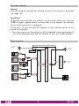
2.4 desCriPtion
The MPEG4 Encoder Cassette converts a HD or SD video and audio signal
into a MPEG4 data stream (transport stream) and outputs it via the ASI inter-
face, the LAN interface and the RF output.
COFDM or QAM modulation can be selected for the RF output signal.
For the Video input it can be selected between HDMI (HDTV with PCM stereo
sound), YPbPr (SD/HD) or CVBS (SD). All common HDTV formats up to a reso-
lution of 1920 × 1080p @ 50/60Hz are supported. The stereo audio signal
of a YPbPr resp. CVBS signal can be fed in via the cinch sockets (analogous)
or the TOSLINK S/PDIF interface (PCM).
A status LED at the HDMI socket lights green, if the present signal is supported
(suitable resolution, no copy protection), or red, if no or a not supported signal
is present.
A status LED at the ASI input indicates, whether a input signal is present
(green).

- 8 - HDE 400
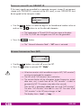
The MPEG4 encoder generates a transport stream according to H.264/AVC
(Advanced Video Coding) High Profile Level 4.0 standard.
At the LAN socket one SPTS/MPTS transport stream (Single/Multi Programme
Transport stream, adjustable data rate) according to UDP or RTP protocol can
be output.
—> Live Streaming/Multicast Streaming requires specially designed
and configured networks. Minimum Requirements include:
Layer-3 Switched Ethernet, Multicast Enabled, IGMPv2/3, Network
and Multicast Routing Supported.
The transport stream can be cascaded via ASI.
IPTV
ASI
QAM/
COFDM
The cassette is designed for use in head-end stations of the standard line.
The operating software of the cassette can be updated via the 9-pin D-SUB
socket "RS-232" using a PC or notebook and the software "BE-Flash".
You can find the current operating software on the website "www.mygss.eu".
signal runtime
Channel switching at a HD source, becomes effective only after a time delay
(of up to 3 seconds) because of the signal runtime!

- 9 - HDE 400
soft ware versions
Cassette
After activating the cassette the software version of the cassette is displayed
(see page 18).
Control unit
To operate these cassettes the software version of the control unit must be
"V45" or higher. Approximately 5 minutes after the last keypress the software
version of the control unit is displayed.
If necessary, you can activate the indication of the software version of the
control unit manually:
• Press any two keys on the control unit of the head-end station simultaneously
until the display goes dark and the software version, e.g.
"
V 45
"
appears
.
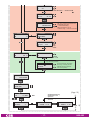
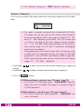
bloCk diagr am
L
R
Pb
Pr
Y/FBAS
Y/CVBS
ASI-Ausgang
ASI output
BNC
ASI-Eingang
ASI input
BNC
IPTV OUT
SPDIF
HDMI
ENCODER
µP / TPS-MODUL
HF Ausgang
HF output
PCM
Audio
PCM
Audio
HDTV
Video
TPS TS
FBAS/CVBS
Component
Bx 2
all
all => RF
all => RF
all, manual
all, manual
FILTER
Bx 2 AUDIO-IN
0 dB
QAM/COFDM-Modulator

- 10 - HDE 400
3 assembly
3.1 installing the Cassette
– Ensure the head-end station is mounted so it will not be able to vibrate.
Avoid, for example, mounting the head-end station onto a lift shaft or any
other wall or floor construction that vibrates in a similar way.
– Before installing or changing a cassette unplug the power cable from the
mains power socket.
• Remove the fastening screws 1 of an unoccupied slot from the bracket of
the head-end station.
• Insert the cassette in this slot and push it into the housing.
• Align the cassette and apply slight pressure to connect it to the connections
of the board and the HF bus bar.
• Fasten the cassette with the screws 1.
1
1

- 11 - HDE 400
3.2 emC regul ations
To comply with the current EMC regulations, it is necessary to connect the lines
leading in and out of the head-end station using cable terminals.
When mounting the cassette in a head-end station which is installed in a 19"
cabinet, make sure the connections leading in and out for the 19" cabinet are
made using cable terminals.
CLASS
KLASSE
The attenuation of shielding of the connection lines for ASI and antenna must
meet the requirements for "Class A".
• Insert the required number of cable terminals in the openings provided in
the head-end station or in the 19
"
cabinet.
Tighten the nuts on the cable terminals until the teeth on the lock washer have
penetrated the exterior coating and a good connection is made between the hous-
ing and cable terminals.
Whenever the HDMI socket is used, the player, which is connected to it, must
be operated inside the station or connected via commercially available optical
fibre, in order to fulfill the EMV regulation for head-end stations.

- 12 - HDE 400
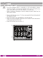
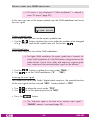
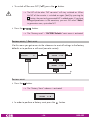
3.3 Casset te overview
12
13
14
15
11
10
9
8
7
6
5
4
3
2
1
1 D-SUB socket "RS 232"
2 Status LED network
3 LAN socket
4 Status LED data transfer
5 ASI output
6 ASI input
7 Status LED ASI input
8 OPTICAL S/PDIF PCM audio input TOSLINK
9 Audio input R analogous
0 Audio input L analogous
! Video input Y/CVBS
@ Video input Pb
# Video input Pr
$ HDMI input
% Status LED HDMI
The operating software of the cassette can be updated via
the 9-pin D-SUB socket "RS 232" using a PC or notebook and
the software "BE-Flash". You can find the current operating
software on the website "www.mygss.eu".
3.4 ConneCting the Cassette
• Dependent on the input signal connect the
source device via cable terminals
to the input sockets
"HDMI"
$
, "Y/Pb/Pr"
!/@/#
or "CVBS"
!
,
"Audio R"
9
, "Audio L"
0
or "OPTICAL"
8
.
• If necessary connect the
ASI input
6
and the
ASI output 5
to the periph-
eral devices
- and/or
• connect the LAN socket 3 to a LAN network.
• Connect the head-end station to the mains.

- 13 - HDE 400
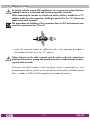
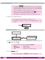
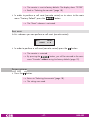
3.5 uPdating the software
The RS 232 interface of the cassette 1 enables you to use a PC or a notebook
and the "BE-Flash" software to update the software of the cassette.
You can find the "BE-Flash" software and the current operating software of the
cassette at the website "www.mygss.eu".
Before updating, the network cable must be disconnected from the LAN socket.
• Use a "one-to-one cable" to connect the cassette’s RS 232 interface and the
PC according to the wiring scheme below.
9-pin
D-SUB socket
9-pin
D-SUB plug
1
2
3
4
5
6
7
8
9
1
2
3
4
5
6
7
8
9
—> For PCs with USB connector (without serial interface), we recom-
mend the DeLOCK "USB 2.0 to Serial adapter" (Product No.
61460).
• Start the "BE-Flash" software and update the software of the cassette.

- 14 - HDE 400
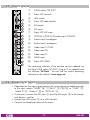
4 the Control Panel at a glanCe
4.1 menu items
Program the cassette using the buttons on the control unit of the head-end sta-
tion. The two-line display of the control unit then shows the menus.
Use the key to select the following main menu items:
– Cassette
– Encoder
– RF Output
– Ethernet
– IPTV Output
– ASI Output
– ASI Input
– Data rate
– TS/ONID
– NIT
– Factory reset
4.2 Control Panel
The key pad on the head-end station is used to scroll through the menus:
scrolls forward through the menus.
scrolls backward through the menus.
select parameters in the menus
selects sub-menus
set values,.
saves all entries.
BE-Remote V 45
please wait . . .

- 15 - HDE 400
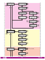
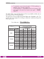
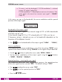
5 Programming
5.1 Programming ProCedure
(Page 17)
(Page 17)
▶
◀
/
nur wenn IP-Adresse außerhalb des
Multicastbereichs liegt
–> Unicastverbindung
only if IP address is out of
multicast range –> Unicast connection
Bx 4 DEST-MAC
0022B7000000
nach Änderung (save)
after modification (save)
Bedienhinweise
"blättert" Menüs vorwärts.
"blättert" Menüs rückwärts.
wählen die Eingabeposition
wählt Untermenü
stellen Werte ein,.
speichert alle Eingaben.
1 zeigt die Eingabeposition
Operating Hints
scrolls forward through the menu.
scrolls backward through the menu.
select the enter position.
selects a submenu.
set values and triggers actions.
saves all entries.
1 shows the enter position
Bx 2
V 7
ENCODER
HD – – –
Bx 2
0x0001,0100
TS/ONID
Bx 1
………
………
………
Bx 3
………
> 2 sec. = abbrechen / cancel
………
………
t > 10 s
Bx 2
off
ETHERNET
=>
stat
DHCP
Bx 2
192.168.
IP-ADDR
0.128
Bx 2
255.255.
IP-MASK
255. 0
Bx 2
192.168.
IP-GATEWAY
0. 1
Bx 2
60000
UDP-PORT
A
A
Bx 2
HD
ENCODER
=>
Bx 2
00001
SERVICE-ID
Bx 2
HD
NAME
Bx 2
10.0 Mbps
1.0 … 30.0 Mbps
Off
Audio only
löschen / delete
BITRATE
Bx 2
HDMI
HDMI
yPbPr
CVBS
VIDEO-IN
nc
Bx 2
auto
auto
1080i50
720p50
HDMI-LIMIT
Bx 2
store
HDMI-LIMIT
(save)
Bx 2
IBBP
IBBP
IPPP
IBP
VIDEO-GOP
Bx 2
CINCH
CINCH
OPTICAL
AUDIO-IN
0 dB
Bx 2
HDMI
AUDIO-IN
0 dB
Bx 2
192 kbps
AUDIO
Stereo
Bx 2 LEVEL
- 6 dB
Bx 2
C69
FREQ
858.00 MHz
OFF/QAM/COFDM
Bx 2
6900 QAM
QAM
QAM
256 POS
Bx 2
Tables
FAILURE
Bx 2
Tables
FAILURE
Bx 2
8MHZ QAM64
COFDM
COFDM
POS
Bx 2
2k C7/8
COFDM
G1/32
Bx 2
0x0000
CELL-ID
off
B
Ein/On
Bx 2
QAM
RF
C69 =>
Bx 2
ASI
OUTPUT
=>
Bx 2
108000 KBits
ASI RATE
Bx 2
188 pos.
/204
/neg.
/burst
ASI OPTION
cont.
Bx 2
ASI
INPUT
OK =>
Bx 2
all
all
manual
all => RF
FILTER
Bx 2
IP
OUTPUT
=>
IP 1
UDP
/RTP
1…7
/ 10/09 AnnexB / … / 20/19 AnnexB
MODE/PORT
1234
IP 1
7 off
PKTS/FEC
IP 1
227. 40.
OUT-IP
50. 60
Services entfernen / hinzufügen
Removing / activating services
nächster Service (Programm)
next service (station)
nur bei Einstellung "manual"
Only with setting "manual"
01/04BX 2 TV +
Das Erste
Bx 2
!
DATARATE
38.3/ 50.9 Mb
B
A
▶
Bx 4
Defaults
FACTORY
=>
Bx 4
STORE
FACTORY
=> M
auf Werkseinstellung
zurücksetzen und
speichern
reset to factory defaults
and store
M
Bx 4
RESET
RESET
=> M
Bx 4A/B
off
NIT
=> Make
▶
on / off
Make
IP 1
( 7.3) >
DATARATE
! 10.0 MB
auto
2 … 80.0/180.0 MBits
▶
◀
/
BE–Remote
please wait …
V 45
M

- 16 - HDE 400
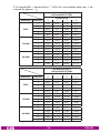
▶
◀
/
nur wenn IP-Adresse außerhalb des
Multicastbereichs liegt
–> Unicastverbindung
only if IP address is out of
multicast range –> Unicast connection
Bx 4 DEST-MAC
0022B7000000
nach Änderung (save)
after modification (save)
Bedienhinweise
"blättert" Menüs vorwärts.
"blättert" Menüs rückwärts.
wählen die Eingabeposition
wählt Untermenü
stellen Werte ein,.
speichert alle Eingaben.
1 zeigt die Eingabeposition
Operating Hints
scrolls forward through the menu.
scrolls backward through the menu.
select the enter position.
selects a submenu.
set values and triggers actions.
saves all entries.
1 shows the enter position
Bx 2
V 7
ENCODER
HD – – –
Bx 2
0x0001,0100
TS/ONID
Bx 1
………
………
………
Bx 3
………
> 2 sec. = abbrechen / cancel
………
………
t > 10 s
Bx 2
off
ETHERNET
=>
stat
DHCP
Bx 2
192.168.
IP-ADDR
0.128
Bx 2
255.255.
IP-MASK
255. 0
Bx 2
192.168.
IP-GATEWAY
0. 1
Bx 2
60000
UDP-PORT
A
A
Bx 2
HD
ENCODER
=>
Bx 2
00001
SERVICE-ID
Bx 2
HD
NAME
Bx 2
10.0 Mbps
1.0 … 30.0 Mbps
Off
Audio only
löschen / delete
BITRATE
Bx 2
HDMI
HDMI
yPbPr
CVBS
VIDEO-IN
nc
Bx 2
auto
auto
1080i50
720p50
HDMI-LIMIT
Bx 2
store
HDMI-LIMIT
(save)
Bx 2
IBBP
IBBP
IPPP
IBP
VIDEO-GOP
Bx 2
CINCH
CINCH
OPTICAL
AUDIO-IN
0 dB
Bx 2
HDMI
AUDIO-IN
0 dB
Bx 2
192 kbps
AUDIO
Stereo
Bx 2 LEVEL
- 6 dB
Bx 2
C69
FREQ
858.00 MHz
OFF/QAM/COFDM
Bx 2
6900 QAM
QAM
QAM
256 POS
Bx 2
Tables
FAILURE
Bx 2
Tables
FAILURE
Bx 2
8MHZ QAM64
COFDM
COFDM
POS
Bx 2
2k C7/8
COFDM
G1/32
Bx 2
0x0000
CELL-ID
off
B
Ein/On
Bx 2
QAM
RF
C69 =>
Bx 2
ASI
OUTPUT
=>
Bx 2
108000 KBits
ASI RATE
Bx 2
188 pos.
/204
/neg.
/burst
ASI OPTION
cont.
Bx 2
ASI
INPUT
OK =>
Bx 2
all
all
manual
all => RF
FILTER
Bx 2
IP
OUTPUT
=>
IP 1
UDP
/RTP
1…7
/ 10/09 AnnexB / … / 20/19 AnnexB
MODE/PORT
1234
IP 1
7 off
PKTS/FEC
IP 1
227. 40.
OUT-IP
50. 60
Services entfernen / hinzufügen
Removing / activating services
nächster Service (Programm)
next service (station)
nur bei Einstellung "manual"
Only with setting "manual"
01/04BX 2 TV +
Das Erste
Bx 2
!
DATARATE
38.3/ 50.9 Mb
B
A
▶
Bx 4
Defaults
FACTORY
=>
Bx 4
STORE
FACTORY
=> M
auf Werkseinstellung
zurücksetzen und
speichern
reset to factory defaults
and store
M
Bx 4
RESET
RESET
=> M
Bx 4A/B
off
NIT
=> Make
▶
on / off
Make
IP 1
( 7.3) >
DATARATE
! 10.0 MB
auto
2 … 80.0/180.0 MBits
▶
◀
/
BE–Remote
please wait …
V 45
M

- 17 - HDE 400
▶
◀
/
nur wenn IP-Adresse außerhalb des
Multicastbereichs liegt
–> Unicastverbindung
only if IP address is out of
multicast range –> Unicast connection
Bx 4 DEST-MAC
0022B7000000
nach Änderung (save)
after modification (save)
Bedienhinweise
"blättert" Menüs vorwärts.
"blättert" Menüs rückwärts.
wählen die Eingabeposition
wählt Untermenü
stellen Werte ein,.
speichert alle Eingaben.
1 zeigt die Eingabeposition
Operating Hints
scrolls forward through the menu.
scrolls backward through the menu.
select the enter position.
selects a submenu.
set values and triggers actions.
saves all entries.
1 shows the enter position
Bx 2
V 7
ENCODER
HD – – –
Bx 2
0x0001,0100
TS/ONID
Bx 1
………
………
………
Bx 3
………
> 2 sec. = abbrechen / cancel
………
………
t > 10 s
Bx 2
off
ETHERNET
=>
stat
DHCP
Bx 2
192.168.
IP-ADDR
0.128
Bx 2
255.255.
IP-MASK
255. 0
Bx 2
192.168.
IP-GATEWAY
0. 1
Bx 2
60000
UDP-PORT
A
A
Bx 2
HD
ENCODER
=>
Bx 2
00001
SERVICE-ID
Bx 2
HD
NAME
Bx 2
10.0 Mbps
1.0 … 30.0 Mbps
Off
Audio only
löschen / delete
BITRATE
Bx 2
HDMI
HDMI
yPbPr
CVBS
VIDEO-IN
nc
Bx 2
auto
auto
1080i50
720p50
HDMI-LIMIT
Bx 2
store
HDMI-LIMIT
(save)
Bx 2
IBBP
IBBP
IPPP
IBP
VIDEO-GOP
Bx 2
CINCH
CINCH
OPTICAL
AUDIO-IN
0 dB
Bx 2
HDMI
AUDIO-IN
0 dB
Bx 2
192 kbps
AUDIO
Stereo
Bx 2 LEVEL
- 6 dB
Bx 2
C69
FREQ
858.00 MHz
OFF/QAM/COFDM
Bx 2
6900 QAM
QAM
QAM
256 POS
Bx 2
Tables
FAILURE
Bx 2
Tables
FAILURE
Bx 2
8MHZ QAM64
COFDM
COFDM
POS
Bx 2
2k C7/8
COFDM
G1/32
Bx 2
0x0000
CELL-ID
off
B
Ein/On
Bx 2
QAM
RF
C69 =>
Bx 2
ASI
OUTPUT
=>
Bx 2
108000 KBits
ASI RATE
Bx 2
188 pos.
/204
/neg.
/burst
ASI OPTION
cont.
Bx 2
ASI
INPUT
OK =>
Bx 2
all
all
manual
all => RF
FILTER
Bx 2
IP
OUTPUT
=>
IP 1
UDP
/RTP
1…7
/ 10/09 AnnexB / … / 20/19 AnnexB
MODE/PORT
1234
IP 1
7 off
PKTS/FEC
IP 1
227. 40.
OUT-IP
50. 60
Services entfernen / hinzufügen
Removing / activating services
nächster Service (Programm)
next service (station)
nur bei Einstellung "manual"
Only with setting "manual"
01/04BX 2 TV +
Das Erste
Bx 2
!
DATARATE
38.3/ 50.9 Mb
B
A
▶
Bx 4
Defaults
FACTORY
=>
Bx 4
STORE
FACTORY
=> M
auf Werkseinstellung
zurücksetzen und
speichern
reset to factory defaults
and store
M
Bx 4
RESET
RESET
=> M
Bx 4A/B
off
NIT
=> Make
▶
on / off
Make
IP 1
( 7.3) >
DATARATE
! 10.0 MB
auto
2 … 80.0/180.0 MBits
▶
◀
/
BE–Remote
please wait …
V 45
M
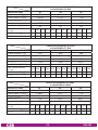
(Page 15)
(Page 15)

- 18 - HDE 400
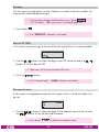
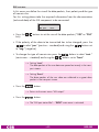
5.2 Programming the Cassette
—> Pressing the button for longer than 2 seconds cancels the
programming procedure. This takes you back to the programme
item "Selecting the cassette" from any menu. Any entries that have
not been saved are reset to the previous settings.
—> Entries in the menus can be saved by pressing the key. You are
taken back to the "Selecting the cassette" menu item.
—> The parameters and functions to be set are underlined (Cursor).
• Switch on the head-end station.
—> The display shows the software version (e.g. V 45)
—> The processor reads the
cassettes
‘ data (approximately 10 sec-
onds).
t > 10 s
Ein/On
BE–Remote
please wait …
V 45
seleCting the Cassette
Bx 2
V 7
ENCODER
HD – – –
Bx 1
………
………
………
Bx 3
………
………
………
• If necessary select the cassette to be programmed by repeatedly pressing
the button (e.g. Box 2).
—>
The display shows e.g. the menu "Bx 2 ENCODER":
"Bx 2" stands for slot 2
"
ENCODER HD
" type of cassette
"V 7" software version of the cassette
• Press the button.
—> The "Encoder settings" – "ENCODER" main menu is activated.

- 19 - HDE 400
enCoder
Via this menu you get access to the submenus in order to do the encoder set-
tings and to select the desired input.
—> If no encoder settings should be done, press button .
The "RF output"
– "RF" main menu is activated (page 23).
• Press button
.
—> The "SERVICE-ID" submenu is activated.
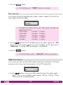
serviCe id (sid)
In this menu you can assign a Service
ID
for the signal which is to be encoded.
Bx 2
00001
SERVICE-ID
• Use the
buttons to
select the digit of the SID to be set and use
buttons to set the desired SID.
—> Take care, not to
assign the same SID twice.
• Press the button.
—> The
"Channel name" – "NAME" submenu is activated.
Progr am me name
In this menu, a programme name for the signal which is to be encoded, can
be set.
Bx 2
HD
NAME
• Use the
buttons to
select the digit of the channel name to be set and
use buttons to set the desired character .
—> Press button to delete the complete name.

- 20 - HDE 400
• Press the button.
—> The
"Total data rate" – "BITRATE" submenu is activated.
total data r ate
In this menu you set the total data rate (video + audio + tables), with which the
input signal shall be encoded.
Bx 2
10.0 Mbps
BITRATE
—> The higher the resolution of the input video signal, the higher the
data rate must be set:
1920x1080p 6,3 Mbit/s…30 Mbit/s
1920x1080i 6,3 Mbit/s…24 Mbit/s
1280x720p 4,3 Mbit/s…24 Mbit/s
720x576i 1,3 Mbit/s…10 Mbit/s
720x480i 2,3 Mbit/s…10 Mbit/s
• Use the buttons to set the data rate of the video signal (1.0…30.0
Mbit/sec). If only audio signals are to be encoded, set the data rate to
"Audio only". In setting "Off" the encoder is switched off.
• Press the button.
—> The "HDMI Video Format" – "HDMI-LIMIT" submenu is activated.
hdmi video format
In this menu you can limit the HDMI video format from "automatic" to a fixed
maximum value if e.g. the communication with a DVD player fails.
Bx 2
auto
HDMI-LIMIT
(save)
• Use the buttons to limit the HDMI video format of the video signal:
– "auto": one of the available video formats 480i/p, 576i/p, 720p,
1080i/p will be set automatically.
Page is loading ...
Page is loading ...
Page is loading ...
Page is loading ...
Page is loading ...
Page is loading ...
Page is loading ...
Page is loading ...
Page is loading ...
Page is loading ...
Page is loading ...
Page is loading ...
Page is loading ...
Page is loading ...
Page is loading ...
Page is loading ...
Page is loading ...
Page is loading ...
Page is loading ...
Page is loading ...
Page is loading ...
Page is loading ...
Page is loading ...
Page is loading ...
Page is loading ...
Page is loading ...
Page is loading ...
Page is loading ...
Page is loading ...
Page is loading ...
-
 1
1
-
 2
2
-
 3
3
-
 4
4
-
 5
5
-
 6
6
-
 7
7
-
 8
8
-
 9
9
-
 10
10
-
 11
11
-
 12
12
-
 13
13
-
 14
14
-
 15
15
-
 16
16
-
 17
17
-
 18
18
-
 19
19
-
 20
20
-
 21
21
-
 22
22
-
 23
23
-
 24
24
-
 25
25
-
 26
26
-
 27
27
-
 28
28
-
 29
29
-
 30
30
-
 31
31
-
 32
32
-
 33
33
-
 34
34
-
 35
35
-
 36
36
-
 37
37
-
 38
38
-
 39
39
-
 40
40
-
 41
41
-
 42
42
-
 43
43
-
 44
44
-
 45
45
-
 46
46
-
 47
47
-
 48
48
-
 49
49
-
 50
50


Ask a question and I''ll find the answer in the document
Finding information in a document is now easier with AI
Related papers
-
GSS PSPT 1000 Assembly Instruction Manual
-
GSS HDE 166 Assembly Instruction Manual
-
-
-
-
-
-
-
-
Other documents
-
Trust MultiCover Widescreen HD User manual
-
Fracarro 283958 Datasheet
-
Triax CCE 210 Assembly Instructions Manual
-
-
-
Televes Modulator Encoder Quick start guide
-
-
-
-