Page is loading ...

1 / 36
■
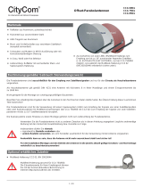
Reektor in bewährter Aluminium-Ausführung, pulver-
beschichtet
■
Speisesystem-Halterung und Spiegel-Hinterkonstruktion aus
verzinktem Stahlblech, pulverbeschichtet
■
Optimale elektrische Daten durch Offset-Speisung bei
geringsten mechanischen Abmessungen
■
Lieferumfang: Reektor und Speisesystem-Halterung, Innen-
sechskant-Schlüssel (SW 5)
■
Mit schwenkbarer Multifeed-Aufnahme zur optimalen Polari-
sationseinstellung. Dadurch können die Speisesysteme in die
für Multifeed-Empfang typischen Nebenbrennpunkte positio-
niert werden
■
Am Tragarm können, ohne zusätzliche Bauteile, zwei Univer-
sal-Speisesysteme zum Empfang von 3° bis 4°
(z. B. ASTRA 19,2°/23,5°) oder 6° (z. B. ASTRA/EUTELSAT-
HOTBIRD) auseinander liegenden Satelliten befestigt werden
CAS 120 20010008
Offset-Parabolantenne
Merkmale
■
Bei 6° Satelliten-Abstand kann zusätzlich auch mittig ein
Speisesystem montiert werden (3 Satelliten mit jeweils 3°
Abstand)
■
Für die Montage zusätzlich erforderlich:
Azimut-/Elevationshalterung ZAS 120.
Bestimmungsgemäßer Gebrauch
Die Parabolantenne CAS120 ist ausschließlich für den Empfang von Satellitensignalen und nur für den Einsatz als
Haushaltsantenne vorgesehen.
Als Haushaltsantenne gilt gemäß DIN 4131 eine Antenne mit höchstens 6 m freier Mastlänge und einem Einspannmoment bis
zu 1650 Nm.
Die Antenne darf nur gemeinsam mit der Halterung ZAS 120 (Bestell-Nr. 218672) montiert werden. Die ZAS120 gehört nicht
zum Lieferumfang der Parabolantenne.
Nicht geeignet für die Montage an schwingungsanfälligen Bauwerken.
Beachten Sie unbedingt die Angaben über die Grenzlast in den Technischen Daten (letzte Seite). Bei Überschreitung dieser Last
können Teile losbrechen!
Die Parabolantenne CAS 120 ist sowohl für die Verwendung mit einem Speisesystem (LNB) zum Empfang der Signale von einer
Satellitenposition als auch für die Verwendung mit zwei oder drei Speisesystemen für Multifeed-Anwendungen zum Empfang der Sig-
nale von Satellitenpositionen mit 3°–4° oder 6° Satellitenabstand konzipiert.
Verwenden Sie die Parabolantenne nicht zu anderen Zwecken als in dieser Anleitung angegeben! Jegliche anderweitige
Nutzung hat den Verlust der Gewährleistung bzw. Garantie zur Folge.
Insbesondere dürfen Sie niemals
● irgendwelche Bauteile verändern oder
● andere Bauteile verwenden, als vom Hersteller ausdrücklich für die Verwendung mit der Antenne vorgesehen.
Andernfalls kann es sein, dass die Antenne nicht mehr ausreichend stabil und sicher ist!
Optional erhältliches Zubehör
■
Azimut-/Elevationshalterung ZAS 120 (BN 218672)
■
Standfuß ZAS 15 (BN 218603)
■
Wandbefestigung ZAS 16 (BN 218606)

2 / 36
● Auf keinen Fall dürfen Sie unter oder in der Nähe von Freileitungen Antennen montieren, andernfalls können viel-
leicht unbedingt erforderliche Mindestabstände unterschritten sein. Halten Sie auch zu den Seiten mindestens 1 m
Abstand zu allen anderen elektrischen Einrichtungen ein!
Bei Berührung oder falls metallische Antennenteile elektrische Einrichtungen berühren, besteht akute
Lebensgefahr!
● Arbeiten Sie niemals bei aufziehendem Gewitter oder während eines Gewitters an Antennenanlagen.
Es besteht Lebensgefahr!
● Montieren Sie niemals Antennen auf Gebäuden mit leicht entzündbaren Dachabdeckungen, z. B. Stroh, Reet oder
ähnlichen Materialien!
● Andernfalls besteht Brandgefahr bei atmosphärischen Überspannungen (statische Aufladung) oder Blitz-
entladungen (z. B. Gewitter).
● Die hier beschriebenen Montageschritte setzen gute handwerkliche Fähigkeiten und Kenntnisse vom Materialver-
halten bei Windeinwirkung voraus. Lassen Sie die Arbeiten daher von einem Fachmann ausführen, wenn Sie nicht
selbst über solche Voraussetzungen verfügen.
● Die montierende Person muss festes und rutschsicheres Schuhwerk tragen, schwindelfrei sein, sich sicher auf dem
Dach bewegen können sowie eine sichere Stand- und Halteposition haben (evtl. am Dach angurten).
● Vergewissern Sie sich, ob das Dach Ihr Gewicht trägt. Betreten Sie niemals brüchige oder unstabile Flächen!
Wenden Sie sich im Zweifelsfall an einen qualizierten Fachhändler oder an einen Fachmann des Dachhandwerks,
um einen geeigneten Montageort zu nden.
● Betreten Sie Dächer oder absturzgefährdete Stellen nur mit einem ordnungsgemäß angelegten intakten Sicherheits-
gurt oder verwenden Sie eine Arbeitsbühne.
● Leitern oder andere Steighilfen müssen in einwandfreiem Zustand (trocken, sauber und rutschfest) sein. Bauen Sie
keine waghalsigen „Klettertürme“!
● Wenn Passanten durch herabfallende Gegenstände während der Montage gefährdet werden können, müssen Sie
den Gefahrenbereich absperren! Achten Sie darauf, dass sich niemand unterhalb des Montageortes bendet.
● Es besteht Lebens-/Verletzungsgefahr durch möglichen Absturz, Durchbruch und durch evtl. herabfallende
Teile sowie die Möglichkeit, dass das Dach beschadigt wird.
● Die jeweiligen landesspezischen Sicherheitsbestimmungen und aktuellen Normen z. B. DIN EN 60728-11 sind zu
beachten.
● Jegliche anderweitige Nutzung oder die Nichtbeachtung dieses Anwendungshinweises hat den Verlust der Gewähr-
leistung bzw. Garantie zur Folge.
Grundlegende Sicherheitsmaßnahmen
Bevor Sie die Parabolantenne montieren, anschließen oder verwenden, beachten Sie unbedingt die Hinweise in dieser Anleitung!
Wenn Sie die Hinweise nicht beachten,
● können durch Fehlverhalten Gefahren für Ihre Gesundheit und Ihr Leben entstehen,
● können durch Fehler bei der Montage oder beim Anschluss Schäden an der Antenne oder am Montageort entstehen,
● haftet der Hersteller nicht für darauf zurückzuführende Fehlfunktionen und Schäden!
Bitte beachten Sie bei Arbeiten an Antennenanlagen Ihre Verantwortung für Ihre Mitmenschen!
Heben Sie die Anleitung für später auftretende Fragen auf und geben Sie diese bei einem Besitzerwechsel an den neuen Besitzer
weiter!
Montageort wählen
Der richtige Montageort ist entscheidend darüber, ob Ihre Parabolantenne sicher aufgebaut ist und optimal funktionieren kann.
Bei der Montageortwahl sind bauwerkstypische Besonderheiten zu berücksichtigen. Bei Montage an Dach- und Gebäudekanten und
zylindrischen Bauwerken ist gemäß DIN 1055, Teil 4 bzw. 4131 mit erhöhten Wind oder Schwingungsbelastungen zu rechnen. Die
dynamischen Eigenschaften der Antenne und des Bauwerks können sich gegenseitig beeinussen und negativ verändern.
Bei Nichtbeachtung kann eine Überschreitung der unter den technischen Daten genannten Grenzbelastung oder Schwingungsfestig-
keit auftreten. Die Parabolantenne muss nicht unbedingt auf das Dach, weil es nicht auf die Höhe über Grund ankommt, sondern
nur auf die freie „Sicht“ zum Satelliten. Deshalb kann ein geeigneter Montageort zum Beispiel auch im Garten, auf dem Balkon, auf
der Terrasse, an einer Fassade oder an einer Garage zu nden sein.
Wenn also möglich, sollten Sie besser nicht auf dem Dach montieren. Sie verringern damit Ihren Arbeitsaufwand und die Gefah-
ren bei Montagearbeiten auf dem Dach!

3 / 36
● Für einen einwandfreien Empfang muss eine freie „Sicht“ in
Richtung Süden (+/- 20°) gewährleistet sein, bei einer Erhe-
bung von etwa 30°. Dann stehen Ihnen folgende Satelliten zur
Auswahl:
1 TÜRKSAT
*)
42° Ost 7 EUTELSAT W 1 10° Ost
2 ASTRA 2-Gruppe
*)
28,2° Ost 8 EUTELSAT W 3 7° Ost
3 ASTRA 3-Gruppe 23,5° Ost 9 THOR 1° West
4 ASTRA 1-Gruppe 19,2° Ost 10 Telecom 5° West
5 EUTELSAT W 2 16° Ost 11 HISPA-Sat 30° West
6 EUTELSAT
HOTBIRD
13° Ost
● Achten Sie darauf, dass sich keine Hindernisse zwischen der
Parabolantenne und dem jeweiligen Satelliten benden (z.
B. Bäume, Dach- oder Hausecken, andere Antennen). Diese
können den Empfang sogar so beeinträchtigen, dass dieser
bei ungünstiger Witterungslage völlig ausfällt.
*)
Empfang abhängig vom jeweiligen Standort und der Ausleuchtzone des
Satelliten
Antenne montieren
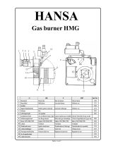
Achten Sie bei der Montage des Antennenträgers (Mast oder
Wandausleger) darauf, dass dieser senkrecht steht. Andernfalls
kann die Ausrichtung der Antenne auf den Satelliten zu
Schwierigkeiten führen.
a. Anforderungen an den Antennenträger
– Verwenden Sie nur Masten oder Tragrohre, die speziell
für Antennenmontage geeignet sind. Andere Rohre oder
Träger haben zumeist nicht die erforderliche Festigkeit bei
Wind- und Wettereinüssen.
– Wählen Sie für die Befestigung der Antenne Rohre mit
einem Durchmesser von 60 bis 90 mm mit einer Wand-
dicke von mindestens 2 mm. Kathrein empehlt für die
Montage folgende Bauteile:
~ Ebenerdig: Standfuß ZAS15
~ Wandmontage: Wandhalterung ZAS16
~ Dachmontage: Mastrohr ZAS03 oder ZAS04
Falls Sie doch auf dem Dach montieren, müssen Sie
beachten, dass, entsprechend EN 60728-11, das zulässige
Moment an der Einspannstellte maximal 1650 Nm betragen
darf.
Daraus ergeben sich für die beiden Windlastfälle 1 und 2 die
maximal zulässigen Mastlängen, siehe Abb. rechts.
Bei Überschreitung des Moments von 1650 Nm an der
Einspannstelle, z. B. durch einen längeren Mast und noch
zusätzliche montierte Antennen, muss gemäß EN 60728-11
für die Gewährleistung der Sicherheit der baulichen Anlage
und/oder des Gebäudes ein Statiker hinzugezogen werden.
Bei einer anderen Bauweise müssen Sie Wind-
last und Biegemoment an der Einspannstelle
gemäß DIN EN 60728-11 errechnen (oder von
einem Fachmann errechnen lassen).
Ø 60-90 mm

4 / 36
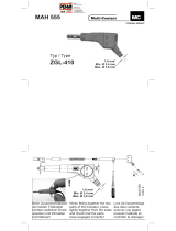
b. Montage Halterung (ZAS 120)
– Befestigen Sie die Azimut-/Elevationshalterung ZAS120
wie aus der Grak rechts ersichtlich.
– Weitere Hinweise zur Montage der Halterung ZAS120
entnehmen Sie dem dort beiliegenden Anwendungshin-
weis.
– Ziehen Sie im Anschluss zwei beliebige der vier Schrau-
ben mit dem Innensechskantschlüssel handfest an.
– Falls Sie beabsichtigen, die Antenne nicht auf der Mast-
spitze zu montieren, müssen Sie vorher den Auagewinkel
Ⓦ von der Halterung abschrauben.
c. Antenne vorbereiten
– Die vier Schrauben aus den Sicherungsholzleisten heraus-
drehen. Entfernen Sie für die weiteren Montageschritte die
Kartonhülle noch nicht. Sie dient zum Schutz der Speise-
systemhalterung. Den Ausleger soweit herausschwenken
bis er am Kartonrand auiegt.
– Parabolspiegel anheben. Dadurch schwenkt der Ausleger
weiter, bis er in die Verriegelung V einrastet.
– Die vier Schrauben S (SW 19) anziehen. Anziehdrehmo-
ment 37–43 Nm.
– Hängen Sie die vorbereitete Antenne in die Halterung
ZAS120 ein.

5 / 36
Multifeed-
Adapterplatte
d. Speisesystem (LNB)
Das/die Speisesystem/e sowie Hinweise zu deren Montage
gehören nicht zum Lieferumfang der Parabolantenne.
Bitte entnehmen Sie daher die näheren Informationen zur
sachgerechten Montage den Anleitungen, die dem jeweiligen
Speisesystem beiliegen.
An der schwenkbaren Haltevorrichtung am Tragarm können
Sie über die Multifeed-Adapterplatte am Tragarm ein, zwei
oder drei Kathrein-Universal-Speisesysteme montieren. Auf
der Adapterplatte zeigt die Markierung
– 3 die Montageposition für ein einzelnes Speisesystem,
– 2 und 4 die Montagepositionen für zwei Multifeed-Speise
systeme bei 3°–4° Satellitenabstand,
– 1 und 5 die Montagepositionen für zwei
Multifeed
-Spei-
sesysteme bei 6° Satellitenabstand. Bei Belegung der
Positionen 1 und 5 kann auch zusätzlich mittig auf Posi-
tion 3 ein Speisesystem montiert werden (3 Satelliten mit
jeweils 3° Abstand)
● Beispiel für Montagepositionen bei einer Mutifeed-Anwen-
dung mit 3°–4° Satellitenabstand:
Pos. 2 Pos. 4
ASTRA 19,2° Ost EUTELSAT 16° Ost
ASTRA 23,5° Ost ASTRA 19,2° Ost
EUTELSAT 16° Ost EUTELSAT 13° Ost
EUTELSAT 13° Ost EUTELSAT 10° Ost
EUTELSAT 10° Ost EUTELSAT 7° Ost
Tipp
Bei Multifeed-Anwendungen sollte die Antenne auf
den Satelliten ausgerichtet werden, der die pegel-
schwächeren Signale sendet.
● Beispiel für Montagepositionen bei einer Mutifeed-Anwen-
dung mit 3°–4° Satellitenabstand:
Pos. 1 (Pos. 3) Pos. 5
ASTRA 23,5° Ost (ASTRA 19,2° Ost) EUTELSAT 16° Ost
ASTRA 19,2° Ost (EUTELSAT 16° Ost) EUTELSAT 13° Ost
EUTELSAT 16° Ost (EUTELSAT 13° Ost) EUTELSAT 10° Ost
HOTBIRD 13° Ost (EUTELSAT 10° Ost) EUTELSAT 7° Ost
Tipp
Bei Multifeed-Anwendungen sollte die Antenne auf
den Satelliten ausgerichtet werden, der die pegel-
schwächeren Signale sendet.

6 / 36
Antenne ausrichten
Die Antenne muss sowohl von der Richtung (Azimut), als auch von
der Neigung (Elevation) her genau auf den Satelliten ausgerichtet
sein. Bei Multifeed-Lösungen sollte die Antenne auf den Satelliten
mit dem schwächsten Signalpegel ausgerichtet werden.
a. Neigung (Elevation) einstellen
– Beim Schwenken der Antenne um die Elelvationsachse
müssen die 6 Schrauben A locker sein. Lösen Sie sie mit
dem der Parabolantenne beiliegenden Innensechskant-
schlüssel.
– Wenn Sie die Antenne per Hand leicht ankippen, können
Sie zum Grob- oder Voreinstellen des Elevationswinkels
die Mutter B (für Feineinstellung) schneller drehen.
– Stellen Sie nun die Neigung (Elevation) ein – den genauen
Elevationswinkel für Ihren Standort nden Sie in der
Anleitung für das Speisesystem (LNB). Stellen Sie diesen
Winkel an der Skala (10° bis 50°) ein. Dabei muss der ent-
sprechende Skalenstrich auf der Halterung mit der Kante
C des Reektorhaltebleches uchten.
– Ziehen Sie im Anschluss daran die Schrauben A leicht an.
e. Polarisationsvoreinstellung
● Ein Speisesystem (Monofeed)
In Abhängigkeit Ihres Standortes und der Position des zu
empfangenden Satelliten stellen Sie am Speisesystem den
Polarisationswinkel entsprechend Tabelle (siehe Anwen-
dungshinweis LNB) ein. Die schwenkbare Adapterplatte
verbleibt dabei in der Nullposition (siehe Grak rechts).
● Mehrere Speisesysteme (Multifeed)
Zur Optimierung des Multifeedempfangs ist die schwenkbare
Haltevorrichtung „H“ entsprechend der hier anhängenden
Tabelle um den Winkel „V“ zu schwenken.
Der Polarisationswinkel am jeweiligen Speisesystem ist nach
folgender Formel einzustellen.
PW
NEU
= PW
TAB
- V
PW
NEU
= einzustellender Polarisationswinkel
PW
TAB
= Polarisationswinkel des gewählten Satelliten gemäß
Tabelle der Bedienungsanleitung des LNBs
V = Einstellwinkel der Haltevorrichtung gemäß gewählter
Satellitenkombination der anhängenden Tabelle
Bei den Einstellungen und der Berechnung auf die Vorzeichen
achten!
Um die Haltevorrichtung schwenken zu können, müssen Sie
zuerst mit dem Innensechskantschlüssel die in den Graken
rechts (Pfeile) markierte Schraube lockern.

7 / 36
b. Richtung (Azimut) einstellen
Für die folgenden Schritte benötigen Sie gegebenenfalls
einen Helfer, falls Sie nicht selbst an einem Antennenmess-
gerät oder Bildschirm mit angeschlossenem Satelliten-
Receiver das Ergebnis der Ausrichtarbeiten beobachten
können. Eine exakte Ausrichtung der Antenne kann nur
mittels eines digitalen Antennenmessgerätes geschehen.
Fragen Sier hierzu Ihren Fachhändler.
–
Stellen Sie am Satelliten-Receiver einen bekannten
Programmplatz ein, um kontrollieren zu können, ob Sie auch
wirklich den gewünschten Satelliten „getroffen“ haben.
– Drehen
Sie die Antenne grob in Richtung Süden. Drehen Sie
dann die Antenne langsam um die Mastachse – nach links
und rechts, bis das eingestellte Programm am
besten zu
empfangen ist.
c. Feineinstellung
– Lösen Sie die Schrauben A an der Elevationsxierung und
schwenken Sie die Antenne leicht nach oben und unten,
bis Sie entweder am Antennenmessgerät das stärkste
Antennensignal messen oder bei optischer Beurteilung
am Bildschirm den besten Bildeindruck erzielen: Hierzu
schwenken Sie die Antenne soweit nach oben und unten,
bis Sie jeweils an die Grenze kommen, wo die ersten
sogenannten „Fischchen“ (analog) oder „Klötzchen“ (digi-
tal) am Bildschirm erscheinen. Stellen Sie die Antenne
dann in die Mitte zwischen diesen beiden Grenzpunkten.
– Korrigieren Sie nun abwechselnd die Richtung (Azimut)
und Neigung (Elevation), bis sich das Mess- oder Bilder-
gebnis nicht mehr verbessert.
Hinweis: Beim Festdrehen der Flügelmuttern an der Schließ-
schelle kann sich die Antenne leicht verdrehen! Dies
sollten Sie bei der Feineinstellung beachten (und even
tuell für eine ganz genaue Einstellung ausnutzen).
Gegebenenfalls optimieren Sie am Ende nochmal den
(die) Polarisationswinkel des (der) Speisesystem(e)s
und den Winkel der schwenkbaren Haltevorrichtung zur
Speisesystembefestigung.
d. Antenne endgültig festschrauben
– Ziehen Sie am Ende alle Schraubverbindungen fest. Kont-
rollieren Sie zum Schluss noch einmal alle Schraubverbin-
dungen auf festen Sitz.
– Die Antennenkabel sind an solchen Stellen mit Kabelbin-
dern zu befestigen, wo die Gefahr besteht, dass sie durch
Windbewegungen scheuern und dadurch beschädigt
werden können.

8 / 36
Erdungs- und Blitzschutzarbeiten dürfen wegen
der Gefahr unzulänglicher Arbeitsergebnisse nur
von hierfür speziell geschulten Fachkräften des
Elektrohandwerks ausgeführt werden!
Führen Sie niemals Erdungs- und Blitzschutz-
arbeiten durch, wenn Sie nicht selbst Fachkraft
mit entsprechenden Kenntnissen sind!
Die hier abgedruckten Hinweise sind keine Auf-
forderung an Nichtfachleute, Erdungs- und Blitz-
schutzarbeiten in eigener Verantwortung durchzu-
führen, sondern dienen der von Ihnen beauftragten
Fachkraft als zusätzliche Information!
Potenzialausgleichsschiene
Netzanschluss
Potenzial-
ausgleichs-
leitung
Potenzialausgleichsschiene
Erungs-
anschluss
Erdungs-
leitung
Potenzial-
ausgleichs-
leitung
Im straffierten Bereich
ist laut Norm eine
Antennenerdung nicht
zwingend erforderlich.
Antenne erden/Blitzschutz
Die Antenne muss gemäß DINEN60728-11 aufgebaut und ent-
sprechend geerdet werden. Von der Erdungspicht ausgenom-
men sind nur solche Antennen:
– die mehr als 2 m unterhalb der Dachkante
– und zugleich weniger als 1,5m von Gebäuden ange-
bracht sind.
Zur Erdung muss der Mast auf kürzestem Weg über einen geeig-
neten Erdungsleiter mit der Blitzschutzanlage des Gebäudes ver-
bunden sein, falls keine Blitzschutzanlage vorhanden ist: mit der
Gebäudeerdung.
Anschlüsse an die Blitzschutzanlage dürfen nur von einem quali-
zierten Blitzschutzanlagen-Installateur durchgeführt werden.
a. Geeignet als Erdungsleiter
– ist ein Einzelmassivdraht mit einem Querschnitt von min.
16mm
2
Kupfer, min. 25mm
2
Aluminium oder min.50 mm
2
Stahl.
b. Nicht geeignet als Erdungsleiter
– sind die Außenleiter der Antennenkabel
– metallische Hausinstallationen (z. B. Metallrohre der
Wasser- oder Heizungsanlage) da die Dauerhaftigkeit der
Verbindung nicht gewährleistet werden kann
– oder Schutzleiter oder Neutralleiter des Starkstromnetz-
tes.
c. Führung von Erdungsleitern
– Antennenkabel und Erdungsleiter dürfen nicht durch
Räume geführt werden, die zur Lagerung von leicht ent-
zündlichen Stoffen dienen (z. B. Heu, Stroh) oder in
denen sich eine explosive Atmosphäre bilden kann (z. B.
Gase, Dämpfe).
– Bei Verwendung der Parabolantenne in kompletten
Antennenanlagen (z.B. Verteilanlagen) müssen zudem
die Erdungsmaßnahmen so ausgeführt sein, dass der
Erdungsschutz auch dann bestehen bleibt, wenn einzelne
Einheiten entfernt oder ausgetauscht werden.
Gefahren können nicht nur durch Gewitter entstehen (Blitz-
schlag), sondern auch durch statische Auadung oder Kurz-
schluss in den angeschlossenen Geräten.
Deshalb muss generell für alle Antennenanlagen aus Sicherheits-
gründen ein Potenzialausgleich aus 4 mm² Kupfer vorgenommen
werden.
Die Kabelschirme aller Koaxialantennen-Niederführungskabel
müssen über einen Potenzialausgleichsleiter mit dem Mast ver-
bunden werden.

Technische Daten
Alle Angaben sind typi-
sche Werte!
Es können Teile losbrechen, wenn Sie die Grenzlast überschreiten!
Typ CAS 120
Bestell-Nr. 20010008
Durchmesser m 1,2
Farbe Weiß (ähnl. RAL 9002)
Empfangsbereich GHz 10,70-12,75
Antennengewinn bei 10,70-11,70 GHz/11,70-12,50 GHz/12,50-12,75
GHz
dBi 41,5/42,15/42,5
Halbwertsbreite
¹)
° 1,43
Systemgüte
²)
Speisesystem mittig
UAS 571/572/584/585
UAS 481
dB/K
22,0/23,0
21,3/22,2
Systemgüte
²)
Speisesystem-Abstand 3°-4°
UAS 571/572/584/585
UAS 481
dB/K
21,8/22,8
21,2/22,0
Systemgüte
²)
Speisesystem-Abstand 6°
UAS 571/572/584/585
UAS 481
dB/K
21,5/22,6
21,0/21,8
Kreuzpolarisationsentkopplung dB > 30
Windäche m
2
1,35
Schwingungsfestigkeit
ETS 300019-2-4 (12.94)
IEC Class 4 M 5
Windlast 1
bei Montagehöhe bis 20 m über Grund
bei Windgeschwindigkeit bis 130 km/h
bei Staudruck 800 N/m2 nach EN 60728-11
N 1296
Windlast 2
bei Montagehöhe höher als 20 m über Grund (Faktor 1,37)
bei Windgeschwindigkeit bis 150 km/h
N 1776
Grenzlast
bei Staudruck 1900 N/m2 (190 km/h)
N 2646
Max. zulässige Windgeschwindigkeit km/h 157
Spannbereich der Mastschelle mm 50-90
Einstellbereich Elevation/Azimut ° 5-50/360
Abmessungen Breite mm 1234
Abmessungen Höhe max. mm 1570
Abmessungen Auslage max. (ab Mastmitte ohne Speisesystem) mm 1408
Verpackungs-Maße mm 1330 x 1330 x 250
Gewicht ca. netto/brutto kg 18,3/29,0
¹) Bei Bandmitte
²) G/T bei 11,3/12,5 GHz bei Standardumgebung (klarer Himmel)

Garantiebedingungen für die Korrosionsbeständigkeit der Antenne
Wichtige Hinweise zu den Garantiebedingungen für die Korrosionsbeständigkeit der Kathrein-Offset-Parabolantennen:
● Die Antenne muss fachmännisch, unter Berücksichtigung der Vorgaben des
ihr beigelegten Anwendungshinweises, aufgebaut und montiert werden
● Die Antenne darf nicht verändert (z. B. angebohrt) werden
● Die Antenne darf nicht mechanisch beschädigt werden (z. B. Deformationen, tiefe oder
großächige Verletzungen bzw. Abschabungen der Pulverschichten und Oberächenbeschichtung)
● Die Antenne darf nicht durch Chemikalien (z. B. aus Lösungsmitteln, Lacken,
Reinigungsmitteln o.ä.) beschädigt werden
● An der Antenne darf nur original Kathrein-Zubehör verwendet werden
Diese Garantiebedingungen sind gültig ab Kaufdatum.
Als Garantienachweis dient ausschließlich der Original-Kaufbeleg.
Weiterhin besteht keine Garantie für Korrosionsbeständigkeit für Folgen höherer Gewalt, z.B. durch Blitzeinschlag oder bei der Ver-
wendung der Antenne in Klimaregionen, die oft wiederkehrende, starke erosive Belastungen aufweisen (z. B. Sandstürme), die die
Schutzschichten innerhalb kurzer Zeit abtragen.
Entsorgung
Elektronische Geräte gehören nicht in den Hausmüll, sondern müssen - gemäß Richtlinie 2002/96/EG DESEUROPÄI-
SCHEN PARLAMENTS UND DES RATES vom 27. Januar 2003 über Elektro- und Elektronik-Alt-geräte fachgerecht ent-
sorgt werden.
Bitte geben Sie dieses Gerät am Ende seiner Verwendung zur Entsorgung an den dafür vorgesehenen öffentlichen Sam-
melstellen ab.
9363656/d/STD/0619/DE | Änderungen vorbehalten.
www.kathrein-ds.com | [email protected]
KATHREIN Digital Systems GmbH | Anton-Kathrein-Straße 1-3 | 83022 Rosenheim | Deutschland | Telefon +49 731 270 909 70

11 / 36
■
Reector made of aluminium, powder coated
■
Feed system support and reector rear part made of galvani-
sed sheet steel, powder coated
■
Optimal electrical data combined with very compact mecha-
nical dimensions due to offset feed
■
Items supplied: reector and feed system support,
hexagon key (size 5)
■
The tiltable multifeed mounting device allows optimum set-
ting of the polarisation angle. In this way the feed systems
can be positioned for feeding into secondary focal points,
e.g. for multifeed reception
■
Without additional components, two universal feed sys-
tems to receive the signals of satellites 3° or 4° (e.g. ASTRA
19.2°/23.5°) or 6° apart (e.g. ASTRA/EUTELSAT-HOTBIRD)
can be mounted on the boom
CAS 120 20010008
Offset parabolic antenna
Features
■
If the satellites are spaced at 6°, an additional feed system
can be tted in the middle (3 satellites at 3° spacing each)
■
Additionally required for mounting:
Azimuth/elevation clamp ZAS 120.
Intended Use
The CAS 120 parabolic antenna is intended solely for the reception of satellite signals and for use only as a domestic antenna.
DIN 4131 species that a domestic antenna should have no more than 6 m free mast length and a xed-end moment up to 1650 Nm.
The antenna may be installed only in conjunction with the ZAS 120 clamp (part no. 218672). The ZAS 120 is not supplied with
the parabolic antenna.
It is unsuitable for mounting on structures that are liable to vibration.
Make absolutely sure that the values for the maximum load listed in the Technical Data (on the last page) are complied with. If this
load is exceeded, parts could break away!
The CAS 120 parabolic antenna is designed both for use with one feed system (LNB) for reception of the signals from one satellite
position and also for use with two feed systems for multi-feed applications for reception of the signals from two satellite positions with
3°-4° or 6° satellite spacing.
Do not use the parabolic antenna for purposes other than those listed in this manual! Any use other than that
specied above will void the warranty or guarantee.
In particular, never
● modify any of its components or
● fit any components other than those expressly intended by the manufacturer for use with the antenna.
Breach of these rules may lead to the antenna no longer being sufficiently stable and safe!
Optional accessories
■
ZAS 120 Azimuth/Elevation support (BN 218672)
■
Stub mast ZAS 15 (BN 218603)
■
Wall mounting ZAS 16 (BN 218606)

12 / 36
● Under no circumstances install antennas in the vicinity of overhead power cables, otherwise the absolutely essen-
tial clearance requirements may no longer be satised. Maintain a clearance of at least 1 m from all other electrical
devices in all directions!
If you or metal parts of the antenna touch any electrical device there is a serious risk of a fatal electric shock!
● Never work on antenna systems during a thunderstorm or when a thunderstorm is approaching.
There is a risk of a fatal electric shock!
● Never install antennas on buildings with easily ammable roof coverings such as straw, reeds or similar materials!
Otherwise there is a risk of fire due to atmospheric over-voltages (static charges) or lightning discharges
(e.g. during thunderstorms).
● The installation operations described here assume good craftsmanship capabilities and knowledge of the behaviour
of materials under the effects of wind. Therefore if you do not possess the required skills, have this work performed
by a specialist.
● The person doing the work must wear strong non-slip footwear, must not be liable to dizziness, must be able to
move around safely on the roof and have a secure standing and attachment position (if necessary, wear a safety
harness when on the roof).
● Make sure that the roof is able to bear your weight. Never walk on fragile or unstable surfaces! In case of doubt,
contact a qualied specialist dealer or specialist roong contractor to nd an appropriate installation location.
● Do not go on to roofs or other high places without a correctly attached safety harness that is in good condition.
Otherwise use a work platform.
● Ladders or other means of climbing must be in faultless condition (dry, clean and non-slip). Never build any
irresponsible “scrambling towers”!
● If there is a risk that passers-by may be injured by items falling from above during installation, you must close off the
risk area using barriers! Make sure that no-one is underneath the installation location.
Risk of death or injury due to falling from the roof, falling through the roof and falling parts, plus the
possibility of damage to the roof.
● The respective national safety regulations and current standards such as DIN EN 60728-11 should be complied
with.
● Any other use or failure to comply with these instructions will result in voiding of warranty coverage.
Basic Safety Instructions
Before you install, connect or use the parabolic antenna, make sure that you comply with the instructions in this manual!
If you disregard these instructions,
● malfunctions may arise, creating risks to your life and health,
● defects in the installation or the connection may cause damage to the antenna or to the attachment point,
● the manufacturer will not accept liability for malfunctions and damage arising!
When working on antenna systems, please remember your duty of care towards your fellow human beings!
Keep the manual for any questions that arise later, and if the building passes to another owner, pass it on to the new owner!
Selecting the Installation Site
It is essential to select the correct installation site. This determines whether your parabolic antenna can be erected safely and perform
to its optimum capabilities.
When selecting the installation site, take account of special features of the structure of the building. If the installation is at the edge of
the roof or the building or on a cylindrical structure, DIN 1055, parts 4 and 4131 species the increased wind and vibration loadings
that should be allowed for. The dynamic properties of the antenna and the structure can mutually inuence each other and cause det-
rimental changes.
Disregarding these considerations can lead to the maximum load or vibration fatigue stress listed in the Technical Data being excee-
ded. The parabolic antenna need not necessarily be mounted on the roof, since the requirement is not height as such but an
unobstructed “view” of the satellite. For this reason, an appropriate installation site might also be found for instance in the garden, on
the terrace, on the face of the building or on a garage.
In fact if other sites are possible, it is better to avoid the roof. This will result in less work for you and will reduce the hazards asso-
ciated with installation work on the roof!

13 / 36
● For good reception, an unobstructed “view” to the south (+/-
20°) must be ensured, at an elevation of about 30°. The fol-
lowing satellites are then available for selection:
1 TÜRKSAT
*)
42° Ost 7 EUTELSAT W 1 10° Ost
2 ASTRA 2-Gruppe
*)
28,2° Ost 8 EUTELSAT W 3 7° Ost
3 ASTRA 3-Gruppe 23,5° Ost 9 THOR 1° West
4 ASTRA 1-Gruppe 19,2° Ost 10 Telecom 5° West
5 EUTELSAT W 2 16° Ost 11 HISPA-Sat 30° West
6 EUTELSAT
HOTBIRD
13° Ost
● Do make sure that there are no obstacles between the para-
bolic antenna and the respective satellite (such as trees,
roofs, house eaves or other antennas). Such items can impair
reception to the extent that during unfavourable stormy wea-
ther the signal is lost altogether.
*) The reception is dependent upon the respective location and the satel-
lite coverage zone
If you arrange the structure differently you
must calculate wind loading and bending
moment at the clamping point as specified in
DIN EN 60728-11 (or have a specialist do the
calculation for you).
Ø 60-90 mm
East
South
West
Clamping point
Wind load 1
(up to 20m above ground)
Wind load 2
(> 20m above ground)
1.1m 0.75m
Installing the Antenna
When installing the antenna carrier (mast or wall boom), ensure
that it is standing upright. Otherwise, there may be problems
with the alignment of the antenna to the satellites.
a. Requirements on the Antenna Carrier
– Use only supports or support tubes that are specially
designed for installation of antennas. Other tubes
generally do not have the strength required to withstand
the forces of wind and weather.
– For securing the antenna, select a tube diameter bet-
ween 60 and 90 mm, with a wall thickness at least 2 mm.
Kathrein recommends the following components for ins-
tallation:
~ On level ground: Stub mast ZAS 15
~ Wall mounting: Wall bracket ZAS 16
~ On the roof: Mast tube ZAS 03 or ZAS 04
If you do decide in favour of roof mounting, you must ensure
that the installation complies with EN 60728-11, which speci-
es a maximum permissible bending moment of 1650 Nm at
the clamping point.
This translates into the maximum permissible mast lengths
for wind loadings shown as cases 1 and 2 in the diagram on
the right.
If a moment of 1650 Nm might be exceeded at the clamping
point, for instance because of a longer mast with additional
antennas mounted on it, EN 60728-11 requires that a struc-
tural engineer should assess the installation to provide veri-
cation of safety of the installation and/or the structure of the
building.

14 / 36
Top installation
Mast-side mounting
remove
b. Fitting the Clamp (ZAS120)
– Attach the ZAS 120 azimuth/elevation clamp as shown in
the diagram on the right.
– Further instructions for attaching the ZAS 120 clamp can
be found in the instructions supplied with the clamp.
– Then use the hexagon key to tighten any two of the four
bolts nger-tight.
– If you intend to t the antenna to a position lower than the
end of the mast, you must rst unscrew the mounting bra-
cket Ⓦ from the clamp.
c. Preparing the Antenna
– Unscrew the four screws from the retaining batten. Do not
yet remove the cardboard surround, until further assembly
steps. This protects the feed system support. Swing the
boom out until it lies on the end of the cardboard.
– Lift up the parabolic reector. This allows the boom to
swing round further, until it registers in the locking point V.
– Tighten the four bolts S (size 19). Tightening torque 37–43
Nm.
– Hook the prepared antenna into the ZAS 120 clamp.

15 / 36
Multi-feed
adaptor plate
d. Feed system (LNB)
The feed system(s) and instructions for their installation are
not included in the scope of supply of the parabolic antenna.
For more detailed information on their correct installation
please refer to the manuals supplied with the respective feed
system.
Using the multi-feed adapter plate on the carrier arm you
can install one, two or three Kathrein universal feed systems.
The markings on the adapter plate are as follows:
– 3 the installation position for one single feed system,
– 2 and 4 the installation positions for two multi-feed feed
systems at 3°–4° satellite spacing,
– 1 and 5 the installation positions for two multi-feed feed
systems at 6° satellite spacing. With positions 1 and
5 occupied, a feed system can also be mounted in the
middle at position 3 (3 satellites at 3° spacing)
● Example for the installation positions for a multi-feed
application with 3°–4° satellite spacing:
Item 2 Item 4
ASTRA 19.2° East EUTELSAT 16° East
ASTRA 23.5° East ASTRA 19.2° East
EUTELSAT 16° East EUTELSAT 13° East
EUTELSAT 13° East EUTELSAT 10° East
EUTELSAT 10° East EUTELSAT 7° East
Tip
For multi-feed applications the antenna should be
aligned towards the satellite which is transmitting the
weakest signal.
● Example for the installation positions for a multi-feed
application with 6° satellite spacing:
Pos. 1 (Pos. 3) Pos. 5
ASTRA 23.5° East (ASTRA 19.2° East) EUTELSAT 16° East
ASTRA 19.2° East (EUTELSAT 16° East) EUTELSAT 13° East
EUTELSAT 16° East (EUTELSAT 13° East) EUTELSAT 10° East
HOTBIRD 13° East (EUTELSAT 10° East) EUTELSAT 7° East
Tip
For multi-feed applications the antenna should be
aligned towards the satellite which is transmitting the
weakest signal.

16 / 36
Aligning the Antenna
The antenna must be exactly aligned towards the satellite in
respect of both the direction (azimuth) and also the inclination
(elevation). For multi-feed applications the antenna should be
aligned towards the satellite which is transmitting the weakest
signal.
a. Adjusting the inclination (elevation)
– When tilting the antenna about the elevation axis, the 6
bolts A must be slack. Slacken them using the hexagon
key supplied with the parabolic antenna.
– If whilst performing coarse or preliminary setting of the
elevation angle you tilt the antenna slightly by hand you
can turn the nut B (for ne adjustment) more quickly.
– Now adjust the inclination (elevation) – the exact eleva-
tion angle for your location can be found in the manual
for the feed system (LNB). Set this angle according to the
scale (10° to 50°). When doing this, the relevant scale gra-
duation on the clamp must be in line with the edge C of
the reector retaining plate.
– When doing this, tighten the bolts A slightly.
Direction of rotation for polarisation angle (PW)
Direction of rotation for angle V for tilting part
e. Polarisation pre-setting
● One feed system (monofeed)
Set the polarisation angle on the feed system according to
the value in the table for your location and the position of the
satellite from which the signal is to be received (see LNB user
instructions). For this the tiltable adapter plate remains in the
zero position (see diagram on the right).
● Multiple feed systems (multi-feed)
To optimise the multi-feed reception, the tiltable support
“H” should be tilted to the angle “V” according to the table
attached to this document.
The polarisation angle on the respective feed system must be
set according to the following formula.
PW
NEW
= PW
TAB
- V
PW
NEW
= polarisation angle to be set
PW
TAB
= polarisation angle of the selected satellite according
to the table in the LNB user instructions
V = setting angle of the support according to the selected
satellite combination of the attached table
With the settings and the calculation, pay attention to
preceding signs!
In order to be able to tilt the support you must rst use the
hexagon key to slacken the bolt shown arrowed in the illus-
tration on the right.

17 / 36
Zenith
Elevation angle
Azimuth angle
West
East
South
Horizon
b. Setting the Direction (Azimuth)
If you yourself are unable whilst performing the adjustments
to read the results of the alignment work on an antenna
meter or screen connected to the satellite receiver, you may
need an assistant for the following steps. The precise align-
ment of the antenna can be achieved only if a digital antenna
meter is used. Ask your dealer about this.
– Set the satellite receiver to a known channel so that you
can check that you have really “locked on” to the desired
satellite.
– Turn the antenna so that it roughly faces south. Then
slowly twist the antenna about its mast axis to left and
right until the best reception is obtained for the selected
channel.
c. Fine Adjustment
– Once again slacken the bolts A on the inclination scale
and tilt the antenna lightly upwards and downwards until
either the antenna meter shows the strongest antenna
signal or visual assessment is judged to achieve the best
picture. To do this, tilt the antenna far enough upwards
and downwards to get to the limits when the rst “little
sh” (analogue) or “little blocks” (digital) appear on the
screen. Position the antenna midway between the two
limit points.
– Now, alternately correct the direction (azimuth) and incli-
nation (elevation) until the measured results or the picture
quality show no further improvement.
Note: Tightening the wing nuts at the clamping pieces can
cause the antenna to turn slightly! You should allow for
this at the fine adjustment stage (and, if necessary, make
use of it when starting the adjustment operation all over
again).
If necessary, once again optimise the polarisation
angle(s) of the feed system(s) and the angle of the
tiltable support for securing the feed system(s).
d. Finally Tightening the Antenna Clamps
– Fully tighten all bolted connections. Finally check once
again that all the bolted connections are secure.
– Attach the cables using cable ties to secure them at any
points where there is a risk they may chafe and suffer
damage in the wind.

18 / 36
Because of the serious consequences if the work
is not done properly, grounding and lightning
protection work may be performed only by spe-
cially trained electricians.
Never perform grounding and lightning pro-
tection work if you are not a specialist with the
appropriate skills!
The instructions printed here are not an invita-
tion to non-specialists to perform grounding and
lightning protection work on their own account;
they are meant solely as additional information for
the specialists whom you employ!
Equipotential bonding rail
Mains connection
Equipotential
bonding
cable
Equipotential bonding rail
Grounding
connection
Grounding
conductor
Equipotential
bonding
cable
According to the stan-
dard, antenna groun-
ding is not compulsory
within the hatched area.
Antenna grounding/lightning protection
The antenna must be erected to DINEN60728-11 and grounded
as specied. The grounding requirement is inapplicable only to
those antennas:
● more than 2 m below the edge of the roof
● and at the same time less than 1.5m from buildings.
For grounding, the mast must be connected by means of a sui-
table ground conductor to the lightning protection system of the
building, using the shortest route. If no lightning protection
system is available: to the building‘s ground conductor.
Connection to the lightning protection system may be made only
by a qualied lightning protection system installation engineer.
a. Suitable as ground conductors are
– a single solid wire with a cross-section of at least 16mm
2
copper, at least 25mm
2
aluminium or at least 50mm
2
steel.
b. Unsuitable as ground conductors are
– the outer conductor of the antenna cable
– metallic domestic installations (such as the metal pipe-
work of a water or heating system), since the permanence
of the electrical connection cannot be guaranteed
– or the shielding conductor or neutral conductor of the
mains power supply.
c. Routing of ground conductors
– Antenna cables and grounding conductors must not be
routed through rooms used for storing easily flammable
substances (such as hay or straw) or in which an explo-
sive atmosphere can develop (such as gases, vapours).
– If the parabolic antenna is used in an integrated antenna
system (e. g. a distribution system), the grounding mea-
sures must also be designed in such a way that groun-
ding protection is still maintained if individual units are
removed or replaced.
Hazards may be caused not only by thunderstorms (lightning),
but also by static charges and short circuits in the connected
units.
For safety reasons therefore in general for all antenna systems
an equipotential bonding conductor of 4mm² copper should be
provided.
The cable screens of all coaxial antenna downlink cables must
be connected to the mast with an equipotential bonding conduc-
tor.

19 / 36
Technical Data
All gures are typical
values!
If the maximum load is exceeded, parts could break away!
Type CAS 120
Part no. 20010008
Diameter m 1.2
Colour White (similar to RAL 9002)
Reception range GHz 10.70-12.75
Antenna gain at 10.70-11.70 GHz/11.70-12.50 GHz/12.50-12.75 GHz dBi 41.5/42.15/42.5
Half-power beam width
¹)
° 1.43
Figure of merit
²)
central feed system
UAS 571/572/584/585
UAS 481
dB/K
22.0/23.0
21.3/22.2
Figure of merit
²)
Feed system spacing 3°-4°
UAS 571/572/584/585
UAS 481
dB/K
21.8/22.8
21.2/22.0
Figure of merit
²)
Feed system spacing 6°
UAS 571/572/584/585
UAS 481
dB/K
21.5/22.6
21.0/21.8
Cross-polarisation decoupling dB > 30
Wind surface area m
2
1.35
Vibration immunity
ETS 300019-2-4 (12.94)
IEC Class 4 M 5
Windload 1
for an installation height up to 20 m above ground
for a wind velocity up to 130 km/h
at a dynamic pressure 800 N/m2 according to EN 60728-11
N 1296
Windload 2
for an installation height higher than 20 m above ground (factor 1.37)
for a wind velocity up to 150 km/h
N 1776
Maximum load
at a dynamic pressure 1900 N/m2 (190 km/h)
N 2646
Max. allowable wind speed km/h 157
Mast clamp range mm 50-90
Setting range Elevation/Azimuth ° 5-50/360
Dimensions width mm 1234
Dimensions height max. mm 1570
Dimensions protrusion max. (from mast centre without feed system) mm 1408
Packing unit dimensions mm 1330 x 1330 x 250
Weight approx. net/gross kg 18.3/29.0
¹
)
At mid-band
²
)
G/T at 11.3/12.5 GHz

Warranty conditions for the antenna corrosion resistance
Important instructions relating to the warranty conditions for the corrosion resistance of Kathrein offset parabolic antennas:
● The antenna must be assembled and mounted professionally, following the steps described
in the enclosed instruction sheet.
● The antenna must not be modied (e.g. by drilling).
● The antenna must not be damaged mechanically (e.g. deformation, deep or extensive damage,
or abrasion of the powder coating and surface coating).
● The antenna must not be damaged due to exposure to chemicals (e.g. solvents, lacquers,
detergents or the like).
● Only genuine Kathrein accessories may be used for the antenna.
These warranty conditions are effective from the date of purchase.
Only the original sales slip is acceptable as proof of purchase for warranty claims.
Furthermore, corrosion resistance is not warranted for the consequences of force majeure, e.g. lightning strike, or if the antenna is
used in regions where frequently occurring, abrasive weather conditions may wear off the protective coating within a short
period of time (e.g. sandstorms).
9363656/d/STD/0619/GB | Subject to change.
www.kathrein-ds.com | [email protected]
KATHREIN Digital Systems GmbH | Anton-Kathrein-Straße 1-3 | 83022 Rosenheim | Germany | Phone +49 731 270 909 70
Waste Disposal
Electronic equipment is not household waste - in accordance with directive 2002/96/EC OF THE EUROPEAN PARLIA-
MENT AND THE COUNCIL of 27th January 2003 on used electrical and electronic equipment, it must be disposed of
properly.
At the end of its service life, take this unit for disposal to an appropriate ofcial collection point.
/