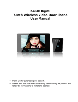
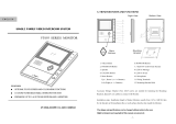
Page is loading ...

Alpha Communications • 42 Central Drive • Farmingdale NY 11735-1202
Toll-Free Technical Line 1-800-666-4800 • Phone: (631) 777-5500 • Fax: (631) 777-5599
Web: www.alphacommunications.com
• Email: [email protected]
Due to continuous product improvement, all colors, sizes, wiring and specifi cations are subject to change without notice.
©Copyright 2014-2015 Alpha Communications®. All Rights Reserved.
VK237 2-Wire Video Intercom Kit
Installation Instructions
AWD188
Rev 3
03/2017
INDOOR MONITOR(S)
TECHNICAL SPECIFICATIONS
Display 7” Color TFT LCD Screen
Monitoring Timer 30 seconds
Talk Timer 120 seconds
Ringtone Timer 30 seconds ringing, 90 seconds waiting
Power Consumption <0.5W (standby), <10W (operating)
Voltage Input to Power Supply 100VAC-240VAC, 50/60Hz
Voltage Output from Power Supply 18VDC, 1500mA
Operational Temperature Range -13°F to 149°F (-25°C to 65°C)
LAYOUT
A. ‘MONITOR’ Button
B. ‘DOOR’ Button 1
C. ‘DOOR’ Button 2 [NOT USED]
D. ‘CALL ON/OFF’ Button
E. Ringtone Volume Adjustment
F. Voice Volume Adjustment
G. Chroma/Contrast Adjustment
H. Brightness Adjustment
I. Microphone
FEATURES
1. Soft-Touch button operation
2. Two-Way voice communication
3. Dual door release options
4. Volume, brightness & contrast adjustable
5. Surface-mounted (low-profi le: 1” deep)
6. 2-Wire installation
CLEANING AND MAINTENANCE
1. Indoor Monitor is not water-proof and do not
use it in high humidity places, like bathrooms.
2. If the screen is dirty, use a soft, dry cloth to
gently wipe the screen.
WARNING
Please use the dedicated power supply provided
in this kit by Alpha Communications®. Use of any
other power supply will void the warranty and
may cause system damage.
GENERAL NOTES
1. Do not put Indoor Monitor in wet areas.
2. Do not place the Indoor Monitor on an unstable
surface, to prevent malfunction or damage
caused by falls.
3. Keep Indoor Monitor out of the reach of small
children.
4. Please do not use needles and other sharp ob-
jects to press the Indoor Monitor buttons.
5. Please don’t hit, shake or throw. Handle with
care.
6. Do not install near any electrical devices, dim-
mers, ballasts or high voltage wiring.
Thumbwheel
Controls
Page 1

TECHNICAL SPECIFICATIONS
Camera Type Color CCD Camera
Camera Viewing Angle 72°
Minimum Illumination 0.1 Lux
Night Light Compensation 4 White LEDs
Power Consumption <0.1W (standby), <3W (operating)
Operational Temperature Range -13°F to 149°F (-25°C to 65°C)
LAYOUT
A. ‘CALL’ Button
B. Name Holder
C. Speaker
D. CCD Camera
E. Microphone
F: LED Illuminators
FEATURES
1. Aluminum alloy panel, vandal resistant
2. Water-resistant
3. Surface-mounted
4. Calling / Talking functions
5. Powered by indoor monitor
6. Backlit call button and name holder
OUTDOOR REMOTE STATION(S)
NOTES:
• Maximum 3 Indoor Monitors and 2 Outdoor Remote
Stations.
• Each Indoor Monitor needs a separate power supply.
• Each Indoor Monitor can monitor each of the (up to 2)
outdoor remote stations.
• Maximum cable length from Outdoor Remote Station to
farthest Indoor Monitor shall not exceed:
• AWG#24 (0.5mm
2
) = 230 feet (70m).
• AWG#22 (0.65mm
2
) = 295 feet (90m).
USER OPERATION
Calling
When the ‘CALL’ button is pressed, the Indoor Monitor(s)
show the visitor’s image from the appropriate Outdoor
Station. Press the ‘TALK’ button to talk to the visitor.
Monitoring
When the ‘MONITOR’ button is pressed from any of the
Indoor Monitors, you can visually monitor and hear the
sounds around the Outdoor Station(s). The monitoring
function will shut off automatically after 30 seconds, or
you can shut off by pressing the ‘MONITOR’ button again.
Unlocking
Under the standby mode or while talking, press ‘DOOR’
button 1, it will activate the dry contact; During a call
from an Outdoor Remote Station‘DOOR’ button 2 is not
used.
Ringtone Volume Adjustment (on the Monitor)
Adjust this to set the volume of the ringtone.
Voice Volume Adjustment (on the Monitor)
Adjust this to set the listening voice volume.
Brightness Tone (on the Monitor)
Adjust this control to adjust the picture brightness.
Chroma/Color (on the Monitor)
Adjust the chroma to get your desired color.
Page 2

SYSTEM WIRING & INSTALLATION
IMPORTANT NOTE
The End-of-Line Resistor Jumper
The End-of-Line Resistor jumper is located on the
back side of the monitor(s), accessible through the
opening in the plastic housing.
If your installation has only a single monitor, the
black plastic end-of-line resistor jumper must remain
in place on the monitor. If your installation has mul-
tiple monitors, the black plastic end-of-line resistor
jumper must remain in place on the monitor which
is farthest from the outdoor remote(s) and must be
removed from the other monitor(s).
Page 3

Side View
Remote Installation Notes:
• The proper height of monitor or door camera is between 63”-67”
(160-170cm) from the ground. This may vary on each installation.
View range should be actively tested before complete.
• Viewing window of door camera is about 19.5” (50cm)vertically,
and 27.5” (70cm) horizontally.
• Narrow space may cause feedback echo on monitor voice function.
• Direct sunshine can cause blurry or ghost-like picture on monitor.
• Installing units too close to electrical lines, dimmers, ballasts, or
other electrical devices may cause audio and/or video interference.
Press down on one side of the
plastic nameplate cover and then
slide the plastic cover towards
that side. The opposite side will
pop up allowing you to remove it.
Top View
Mounting Instructions
Removing Remote Nameplate
Secondary Door Chime (Option)
A secondary door chime push button can be connected to a monitor to the terminal located on the back of the
monitor marked CN5. This can be used as a notifi cation that a visitor has reached a second door after being let
through the fi rst door. When the push button is depressed the monitor will chime twice.
Page 4
/


