Page is loading ...

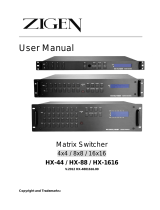
HDMI
SELECTOR
(HRM-2514)
(HRM-2518)
USER MANUAL V1.0
HRM-2514 / HRM-2518
Package Contents -
1 AVLINK HRM-2514 or HRM-2518 HDMI
Selector
1 user manual
1 power adapter DC 12V/1.25A
1 remote controller
1 RS-232 1.8M cable (DB-9 Male to Female)
2 rack rails, 8 screws for HRM-2518 only
Any thing missed, please contact with your vendor.
-1-
Features
Support resolution up to 4K x 2K@60Hz (8-bit) or
1080P@60Hz (12-bit)
HDCP2.2/HDCP1.4 Compliant
Support HDR
Compliant with the specification of HDMI.
Support RS-232 control.
Remote controller for operation.
Hot pluggable.
Auto skips over the power-off and unplugged cable.
Specification
Function HRM-2514
HRM-2518
HDMI Input Connector
(A-Type Female)
4 8
HDMI Output Connector
(A-Type Female)
1
LEDs
On Line 4 8
Selected 4 8
Select Switch 4 8
RS-232 Connector 1x DB-9 Female
Max Pixel clocks 600MHz
Power Adapter (Min.)
DC 12V
1.25A
DC 12V
1.25A
Housing Metal
Weight 600g 1210g
Dimensions (LxWxH) mm
200x75x45
342x104x45
Hardware Requirements
Requirement specifications
HDTV
One LCD, PLASMA TV or projector
with HDMI input function.
DVD player
/ TV Receiver
HDMI output function.
Cable HDMI male to male Standard cable.
-2-
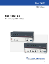
FRONT VIEW
1. Port Selection Switches (Manual type)
Press the switch to access the selected DVD
player/TV receiver.
2. Port LEDs
All the red LEDs flash while the power adapter is
well connected.
Green LEDs light up while the DVD player/TV
receiver has well connected and starting
operation.
Red LEDs light up while the DVD player/TV
receiver has successfully been selected.
3. IR Receiver
Take aim at IR receiver with remote controller.
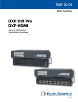
Rear View
1 Power Supply
Plug the DC 12V power adapter.
2. RS232 Port Connector
Plug the RS-232 cable.(Optional)
3. HDMI OUT Port Connector
Plug the monitor cable.
4. HDMI IN Port Connectors
Plug the extension cables from HDMI port of HDMI
output port of device.
-3-

Installation
Before the installation, making sure the selector and
monitor (projector) are turning off.
1. Making sure all equipments are turned off.
2. Plug the monitor cable into the HDMI OUT port
connector.
3. Plug the extension cables from HDMI port of DVD
player/TV receiver into the HDMI IN port connectors.
4. Plug the power adapter into the wall socket.
5. Connect the power adapter with the HDMI selector.
6. Turn on the monitor first.
7. All red LEDs will flash back and forth, otherwise, go
back to check the step 4 and 5.
8. Turn on the DVD player/TV receiver.
9. The LEDs green light turn on while the DVD player/TV
receiver have well been connected and maintaining
the activation.
Operation
1. Port selection
Press the button of “port selection switch” for
accessing the wanted DVD player/TV receiver.
The selected corresponding port will light on for the
red LEDs which indicating the port is actived.
2. IR remote control
Use “1”, ”2” key to select DVD player/TV receiver
that wanted DVD player/TV receiver.
Use “
▲
”, “
▼
” key to select another DVD
player/TV receiver.
3. RS-232 control
You can operate and configure the Switcher via a remote
terminal session using RS-232. Follow the steps as
below to log into the Switcher by means of a RS-232
session (the example as below is for Hyper Terminal):
1. Connect the Switcher to your control PC with RS-232
cable.
2. Power on both Switcher and control PC.
3. Open the Hyper Terminal by clicking
Start│Programs│Accessories
Communications│Hyper Terminal on your control PC.
4. The New Connection – Hyper Terminal screen will
appear. Input the connection name and select a
representative icon. Then click OK.
5. Select the connecting port that you want to use, click
OK. Default port is COM1.
-4-
6. Set the Bits per second to 9600, Data Bits to 8
(Default), Parity to None (Default), Stop bits to 1
(Default) and flow control to None from the drop-down
list, click OK.
Technical Specifications
HDMI Input/Output Signal
Pin #
Signal
Pin #
Signal
1
TMDS Data 2+
11
TMDS Clock Shield
2
TMDS Data 2 Shield
12
TMDS Clock -
3
TMDS Data 2-
13
CEC
4
TMDS Data 1+
14
Reserved
(N.C. on device)
5
TMDS Data 1 Shield
15
SCL
6
TMDS Data 1-
16
SDA
7
TMDS Data 0+
17
DDC/CEC Ground
8
TMDS Data 0 Shield
18
+5 Power
9
TMDS Data 0-
19
Hot Plug Detect
10
TMDS Clock+
Supported RS232 DCE Signal
Pin #
Signal
Pin #
Signal
1 N/A 6 N/A
2 Transmit Data 7 N/A
3 Received Data 8 N/A
4 N/A 9 N/A
5 Signal Ground
-5-
© C&C TECHNIC TAIWAN CO., LTD. All rights reserved.
Trademarks:
All the companies, brand names, and product names
referred to this manual are the trademarks or registered
trademarks belonging to their respective companies.
-6-
/