Page is loading ...

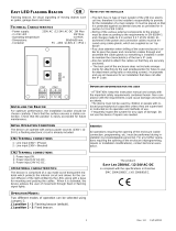
To Remove the Remote Indicator from its Sleeve
Ease the latching ears outwards and pull the unit
forward.
When plugging back in ensure that the latching ears
click into place to maintain the IP65 sealing
Installation
1. Cut out the panel to the size shown.
2. Fit the IP65 sealing gasket behind the front bezel of the
unit
3. Insert the unit in its sleeve through the cut-out.
4. Spring the panel retaining clips into place. Secure the
unit in position by holding it level and pushing both
retaining clips forward.
5. Peel off the protective cover from the display
This remote indicator is intended for permanent installation,
for indoor use only, and enclosed in an electrical panel
Select a location which is subject to minimum vibrations, the
ambient temperature is within 0 and 55
o
C (32 - 131
o
F) and
humidity 5 to 95% RH non condensing.
The unit can be mounted on a panel up to 15mm thick
To ensure IP65 front sealing against dust and water, mount on
a non-textured surface.
Recommended Minimum Spacing
If more than one unit is mounted in the same panel they
should be spaced to allow sufficient air flow between
them.
45 mm
- 0.0 + 0.6
1.77 inch
-0.00, +0.02
Panel Cut-out
Model 32h8e
92 mm - 0.0 + 0.8
3.62 inch - 0.00, +0.03
10mm (0.4 inch)
38mm (1.5 inch)
(Not to scale)
Sensor (Measuring) Input
• Do not run input wires with power cables
• When shielded cable is used, it should be grounded at one point only
• Any external components (such as zener barriers) connected between sensor and input terminals may cause errors in measurement due
to excessive and/or un-balanced line resistance, or leakage currents.
• Sensor input not isolated from the logic outputs & digital inputs
-
+
V+
V-
•
Use the correct compensating
cable preferably shielded.
VI
V+
V-
V- Lead compensation
V+ and VI PRT
2.49
Ω
-
+
V+
V-
Voltage
Thermocouple
RTD
•
The resistance of the three wires must
be the same. The line resistance may
cause errors if it exceeds 22Ω.
Linear mA or mV
•
With this adaptor fitted sensor break alarm does not
operate.
• For a 0-10Vdc input an external input adapter is
required (not supplied). Part number: SUB21/IV10.
100K
Ω
806Ω
0-10V
V+
V-
+
-
•
For mA input
only
connect the
2.49Ω resistor supplied between
the V+ and V- terminals as shown
Safety and EMC Information (continued)
Caution:
Live sensors. The remote panel is designed to operate if the temperature sensor is connected directly to an electrical heating
element. However, you must ensure that service personnel do not touch connections to these inputs while they are live. With a live sensor,
all cables, connectors and switches for connecting the sensor must be mains rated for use in 230Vac +15%: CATII.
Wiring. It is important to connect the unit in accordance with the data in this sheet. Wiring must comply with all local wiring regulations,
i.e. UK, the latest IEE wiring regulations, (BS7671), and USA, NEC Class 1 wiring methods.
!
Do not connect AC supply to low voltage sensor input or low level inputs and outputs.
Voltage rating. The maximum continuous voltage applied between any of the following terminals must not exceed 230Vac +15%:
• relay output to logic, dc or sensor connections;
• any connection to ground.
The Remote Panel must not be wired to a three phase supply with an unearthed star connection. Under fault conditions such a supply
could rise above 264Vac with respect to ground and the product would not be safe.
Conductive pollution. Electrically conductive pollution i.e. carbon dust, MUST be excluded from the enclosure in which the Remote Panel
is installed. To secure a suitable atmosphere in conditions of conductive pollution, fit an air filter to the air intake of the enclosure. Where
condensation is likely, include a thermostatically controlled heater in the enclosure.
Grounding of the temperature sensor shield. In some installations it is common practice to replace the temperature sensor while the
Remote Panel is s
till powered up. Under these conditions, as additional protection against electric shock, we recommend that the shield of
the temperature sensor is grounded. Do not rely on grounding through the framework of the machine.
Over Temperature Protection. To prevent overheating of the process under fault conditions, a separate over-temperature protection
unit should be fitted which will isolate the heating circuit. This must have an independent temperature sensor. The 32h8e is intended for
this function.
Note: Alarm relays within the unit will not give protection under all failure conditions.
Installation Requirements for EMC.
To comply with European EMC directive certain installation precautions are necessary:-
• General guidance. Refer to EMC Installation Guide, Part no. HA025464.
• Relay outputs. It may be necessary to fit a suitable filter to suppress conducted emissions. Filter requirements depend on the type of
load.
• Table top installation. If using a standard power socket, compliance with commercial and light industrial emissions standard is usually
required. To comply with conducted emissions standard, a suitable mains filter must be installed.
Digital Communications
Digital communications uses Modbus protocol - EIA485 (3-wire) and is used to communicate with EPower using the RJ45 socket on
the underside of the EPower controller.
32h8e Terminal
RJ45 Pin Number
HD
Common
3
HE
Rx A(+)
2
HF
Tx B(-)
1
•
EIA485 (3-wire)
• Isolated 240Vac.
Common
Rx A(+)
Tx B(-)
HD
HE
HF
Outputs
•
Isolated output 240Vac CATII
• Contact rating: 2A 264Vac resistive
• Output functions: Alarm
The unit is supplied as standard with a changeover relay on output 1 and analogue (voltage or current) on output 3.
Output 1 Relay (Form C changeover)
1A
1B
2A
OP1
•
Isolated output 240Vac CATII
• Used for analogue retransmission of PV
• Configurable: 0-20mA, 4-20mA, 0-5V, 0-10V, 1-
5V, 2-10V.
• Max load resistance: 500Ω
• Calibration accuracy: +(<0.25% of reading +
<50
µ
A)
Output 3 Analogue (V or mA)
3A
3B
OP3
+
-
Wiring
Wire Sizes
The screw terminals accept wire sizes from 0.5 to 1.5 mm (16 to 22AWG). Hinged covers prevent hands or metal making accidental contact
with live wires. The rear terminal screws should be tightened to 0.4Nm (3.5lb in).
!
Ensure that the
supply to the unit does not
exceed 230Vac +15%.
Terminal Layout 32h8e
Output 3 (OP3)
PV Retransmission
V/mA
Dig in B
Output 1 (OP1)
Changeover Relay
B(-) A(+) COM
Digital Comms
-
+
T/C
Sensor Input
Pt100
V- V+ VI LA C CT HF
HE
HD AC AB AA
N L
-
2.49
Ω
mV/V
+
-
+
Dig in A
Line Supply
100 to 230Vac 48/62Hz
mA include the 2.49Ω load resistor
3D 3C
3A LC
LB 2B
2A
3B
1B 1A
Tx/B/+
* General Notes about Relays and Inductive Loads
When switching inductive loads such as contactors or solenoid valves, wire the 22nF/100Ω ‘snubber’ supplied across normally open relay
terminals. This will prolong contact life and reduce interference.
!
WARNING Snubbers pass 0.6mA at 110V and 1.2mA at 230Vac, which may be sufficient to hold on high impedance loads. Do
not use in these installations.
Example Wiring Diagram
This diagram is not intended to show load connections, load fusing, isolator, or other components associated with high power connections.
It shows communications connections and the over temperature contactor connections.
Do not switch power off to the EPower controller.
White/
Green
Contactor
EPower
driver
Screen
Furnace
Temperature
Thermocouple
Local ground
RJ45
connector
EPower
Power
Unit
L1
L2
L3
EPower
Power
Unit
EPower
Power
Unit
coil
N
32h8e Fuse
L
-
+
N L
-
+
*
3D
3C
3B
3A
LC LB
1B 1A
2B 2A
V-
AA
CT
Auxiliary circuit fuse
V+
C
V1
LA
HD
AC
HF
AB
N
White/Orange
Orange
Com
Rx/A/+
A 5M lead is supplied with the
unit part number LA029798.
HE
Unpacking and Dimensions
32h8e EPower Remote Panel – Installation and Operating Instructions
Model number 32h8e is a horizontal 1/8 DIN indicator and alarm unit that performs the dual function of remote display for EPower and
independent ‘policeman’. The latter is intended to disconnect power should an over temperature (or other excess process condition)
occur.
32h8e communicates with EPower using Modbus protocol via the 3-wire EIA485 RJ45 connector located on the underside of the EPower
driver.
The remote panel is normally ordered as an option with EPower units. It is a fixed hardware build consisting of a relay output in OP1 and
an analogue output on OP3. There is no user communications since this is used to communicate with EPower and the supply is high
voltage only (100 – 230Vac). The unit is configured using a ‘Quick Start’ code on initial start up.
This installation sheet provides step by step instructions to help you to install, wire, configure and use the remote panel.
32h8e is based on indicator series 3200i and has the same and additional features as this instrument. For features not covered in these
instructions, please refer to 3200i User Guide Part No HA029006.
This guide and other related handbooks such as EPower User Guide (part No HA179769) can be downloaded from www.eurotherm.co.uk.
Contents of Package
1x Indicator mounted in sleeve
2 x Panel retaining clips
1 x IP65 sealing gasket mounted on the
sleeve
1 x Component packet containing:-
• A snubber for the alarm relay output (see
‘General Notes about Relays and Inductive
Loads’).
• 2.49Ω resistor for current inputs (see
‘Sensor Measuring Input’).
5 metre cable RJ45 to spade terminals
HA029782/6 CN31557 04/14
Latching ears
IP65 Sealing Gasket
Panel retaining clips
Sleeve
A
A
48mm (1.89inch)
B
96mm (3.78 inch)
C
12.5mm (0.5 inch)
D
90mm (3.54 inch)
B
Side View
Front View
View from
below
D
C
Safety and EMC Information
This instrument is intended for industrial temperature and process control applications within the requirements of the European Directives
on Safety and EMC.
The information contained in this manual is subject to change without notice. While every effort has been made to ensure the accuracy of
the information, your supplier shall not be held liable for errors contained herein.
!
The safety and EMC protection can be seriously impaired if the unit is not used in the manner specified. The installer must ensure the
safety and EMC of the installation.
Safety. This instrument complies with the European Low Voltage Directive 2006/95/EC, by the application of the safety standard EN 61010.
Unpacking and storage. If on receipt, the packaging or unit is damaged, do not install but contact your supplier. If being stored before use,
protect from humidity and dust in an ambient temperature range of -10
O
C to +70
O
C.
Electrostatic discharge precautions. Always observe all electrostatic precautions before handling the unit.
Service and repair. This instrument has no user serviceable parts. Contact your supplier for repair.
Cleaning. Isopropyl alcohol may be used to clean labels. Do not use water or water based products. A mild soap solution may be used to
clean other exterior surfaces.
Electromagnetic compatibility. This instrument conforms with the essential protection requirements of the EMC Directive 2004/108/EC, by
the application of a Technical Construction File. It satisfies the general requirements of the industrial environment defined in EN 61326.
Caution:
Charged capacitors. Before removing an instrument from its sleeve, disconnect the supply and wait at least two minutes to allow
capacitors to discharge. Avoid touching the exposed electronics of an instrument when withdrawing it from the sleeve.
Safety Symbols. Symbols used on the instrument have the following meaning:
!
Caution, refer to accompanying documents)
Equipment protected throughout by DOUBLE INSULATION
Installation Category and Pollution Degree. This unit has been designed to conform to BSEN61010 installation category II and pollution
degree 2, defined as follows:-
• Installation Category II (CAT II). The rated impulse voltage for equipment on nominal 230V supply is 2500V.
• Pollution Degree 2. Normally only non conductive pollution occurs. However, a temporary conductivity caused by condensation must be
expected.
Personnel. Installation must only be carried out by suitably qualified personnel
Enclosure of Live Parts. To prevent hands or metal tools touching parts that may be electrically live, the Remote Panel must be installed in an
enclosure.
!
Ensure that you have the correct supply for your instrument
1. Check order code of the remote panel supplied
2. Use copper conductors only.
3. The power supply input is not fuse protected. This should be provided externally.
Safety requirements for permanently connected equipment state:
• A switch or circuit breaker shall be included in the building installation
• It shall be in close proximity to the equipment and within easy reach of the operator
• It shall be marked as the disconnecting device for the equipment.
Note: a single switch or circuit breaker can drive more than one instrument.
Remote Panel Power Supply
Line
Neutral
L
N
•
High voltage supply: 100 to 230Vac, +/-15%,
48/62 Hz
• Recommended external fuse ratings are as
follows:-
Fuse type: T rated 2A 250V.

If EPower is configured via QuickStart and the functionality of the Analogue Input is not set to Setpoint then the Quick Start does not enable
any of the SetProv function blocks, allowing each Control Block setpoint to be set locally.
If EPower is configured via the Graphical Wiring Editor (using iTools configuration package) then it is possible to enable all of the SetProv
function blocks, allowing each Control Block to have individual setpoints either local or remote.
This flexibility has an impact on the 32h8e with regard to the availability of the Setpoint parameters and when the REM/MAN beacons should
be lit.
It should be noted that it is assumed that if the user requires another source for the Control.Setpoint i.e. a user value then the user will wire
the user value to one of the SetProv’s remote setpoints and NOT directly to the Control’s setpoint.
EPower SetProv Configurations
If EPower is configured via Quick Start and the functionality of the Analogue Input has been set to Setpoint then, in a multiple network
configuration, the Quick Start will wire SetProv.1 to all of the networks associated Control.Main.SP, allowing each Control Block to share
the same local or remote setpoint. This is shown in the diagrams below which are taken from iTools configuration package.
Multiple Single Phase Configuration
2x2 Leg Configuration
REM / MAN Beacons
The REM / MAN beacons are dependent upon which Network the currently displayed value is associated with. However, they are also
dependent upon which, if any, SetProv function blocks are enabled as described below:
When displaying a Network 1 parameter
If no SetProv blocks are enabled then the MAN beacon is always lit else REM / MAN depends upon SPselect of SetProv.1
When displaying a Network 2 parameter
• If no SetProv blocks are enabled then the MAN beacon is always lit
• If 2x2Leg configuration and SetProv.1 and SetProv.3 are enabled then REM / MAN depends upon SPselect of SetProv.3
• If 2x2Leg configuration and SetProv.1 is enabled but SetProv.3 is not then REM / MAN depends upon SPselect of SetProv.1
• If single phase configuration and SetProv.1 and SetProv.2 are enabled then REM / MAN depends upon SPselect of SetProv.2
• If single phase configuration and SetProv.1 is enabled but SetProv.2 is not then REM / MAN depends upon SPselect of SetProv.1
When displaying a Network 3 parameter
• If no SetProv blocks are enabled then the MAN beacon is always lit
• If SetProv.1 and SetProv.3 are enabled then REM / MAN depends upon SPselect of SetProv.3
• If SetProv.1 is enabled but SetProv.3 is not then REM / MAN depends upon SPselect of SetProv.1
When displaying a Network 4 parameter
• If no SetProv blocks are enabled then the MAN beacon is always lit
• If SetProv.1 and SetProv.4 are enabled then REM / MAN depends upon SPselect of SetProv.4
• If SetProv.1 is enabled but SetProv.4 is not then REM / MAN depends upon SPselect of SetProv.1
Setpoint Availability
Multiple Single Phase Configuration
SetProv
1
Control
1
Control
2
Control
3
With SetProv.1 supplying all
control blocks then only the
setpoint for network 1 is
available on 32h8e.
Control
1
Control
2
Control
3
With no SetProv.1 function blocks
enabled then the setpoints for
network 1, network 2 and
network 3 are available on
32h8e.
SetProv
1
Control
1
Control
3
With SetProv.1 supplying both
control blocks then only the
setpoint for network 1 is
available on 32h8e.
Control
1
Control
3
With no SetProv.1 function blocks
enabled then the setpoints for
network 1 and network 2 are
available on 32h8e.
SetProv
1
Control
1
Control
3
SetProv
3
With each network being wired
from its own SetProv then the
setpoints for network 1 and
network 2 are available on 32h8e.
2x2 Leg Configuration
Note: These diagrams show wiring within the EPower unit.
SetProv
1
Control
1
Control
2
SetProv
2
SetProv
3
With each network being wired
from its own SetProv then the
setpoints for network 1, network 2
and network 3 are available on
32h8e.
Control
3
Navigation in Levels 3 and Configuration
The structure is the same in both levels but in Configuration level more parameters are available.
Parameters are listed under headings associated with a particular function. The function heading is chosen by repeatedly pressing
. Parameters associated with the function are selected by repeatedly pressing .
The list of parameters under each heading is the same as the 3200i series and these are listed in the manual HA029006
downloadable from www.eurotherm.co.uk. The exception to this are three additional parameters in the Access List. These are
described below.
Press
to continuously scroll around the list headers
conf
Configuration
level
Input
INPUT
Output 1
OP-1
OP-3
1.ID
3.ID
L.TYP
A1.TYP
REC.N
ID
PHASE
GOTO
IN.TYP
Output 3
Logic
input A
LA
Logic
input B
LB
ALARM
4.TYP
Alarm
Recipe
RECIPE
Digital
comms
COMM
CAL
Calibration
Access
ACCES
First parameter in the list.
Press
to continuously
scroll further parameters.
I
↓
A.SCRL
H.HOME
CTL.SP
Additional parameters
unique to 32h8e – see
below.
Level 3 and Configuration Level
Level 3 makes all operating parameters available (if not read only). It is typically used when commissioning the indicator. Examples are
Input filter time constant, alarm latching, alarm delay, etc.
Configuration Level will enable the fundamental characteristics of the indicator to be changed. This includes parameters in the Quick
Configuration code plus others.
Operation at both levels is explained in the 3200i Engineering Handbook Part No. HA029006 which can be downloaded from
www.eurotherm.com.
The sections on this page describe features which are additional to or differ from those available in the standard 3200i series indicators.
To Select Access Level 3
From any display press and hold for more than 5 seconds. Lev 3 will be displayed followed by code. Press or enter the
passcode – 3 by default for a new instrument.
To Select Configuration Level
When Lev 3 is displayed and before code is displayed, press or to ‘goto’ Conf. Press or enter the passcode – 4 by default for
a new instrument. The mnemonic Conf will appear in the display
To Return to Lower Levels
Press and hold until goto appears. Press or to select the required operating level. It is not necessary to enter a passcode when
going from a higher level to a lower one.
Note: EPower summary parameters are not available in Level 3 or Configuration Level.
Features Which Differ from Standard 3200i Indicators
32h8e does not include Strain Gauge, 24Vac/dc Supply, User Digital Communications.
The following features are unique to 32h8e.
To Turn On Auto-scrolling (
A.SCRL
)
In Configuration level, press to scroll to ACCES list. Press until A.SCRL (long message AUTO SCROLLING) is displayed. Press
or to select 5, 10, 30 or OFF. This sets the duration between scrolls in seconds.
To Hide the HOME Display (
h.home
)
In the ACCES list press until h.home (long message HIDE HOMEPAGE) is displayed. Press or to select y es.
Control and Setpoint Display (
ctl.sp
)
Press or to select yes or No. See also ‘Setpoint Editing’ section.
If set to YES the EPower control parameters (Current, Voltage, or Power) can be viewed, in Operator level, simultaneously with it’s
associated Setpoint. When displaying an EPower control parameter the bottom line of the display is used to display the working
setpoint.
When set to No the bottom line of the display is used to display the parameter name and parameter description (as per other indicator
displays).
PV Retransmission
An EPower unit will generally be part of a wider system, and as such EPower parameters may be communicated to a Fieldbus Network
Master i.e. SCADA package, PLC or DCS system. The 32h8e is an independent policeman, and, therefore, the process PV may also be
communicated to the Fieldbus network master.
To this end, the 32h8e PV is periodically (every 0.5 second) written to the EPower’s Instrument.Config.RemotePV parameter, which can be
transmitted to the master device.
It should be noted that PV retransmission is also provided as an analogue (V or mA) signal using the analogue output OP3. This may be
used as a back-up to the digitally communicated parameter in the event of a failure of the communications link
HOME Page Timeout
The 32h8e will inherit a HOME Page timeout from the 32h8i, this forces the display to go back to the HOME page after a period of
keyboard inactivity.
However, in the 32h8e, if the current focus is on an EPower parameter then the HOME Page timeout will not be imposed.
This will allow the user to display a specific EPower Network parameter indefinitely (auto-scrolling must be disabled).
Digital Alarm Outputs
In the 32h8e up to 4 source parameters can be logically OR’ed together to give a digital output state see Engineering Handbook Part No.
HA029006. The list of source parameters has the following addition to 1.SRC.A, 1.SRC.B, 1.SRC.C AND 1.SRC.D:-
Ep.aL
All EPower alarms
Note the ALL.A (All Alarms parameter) also includes the above EPower alarms as well as indicator alarms.
Manufacturing Address
U.K. Worthing
Eurotherm Ltd
T(+44) 1903 268500
www.eurotherm.co.uk
© Copyright Eurotherm Ltd
TM
2014
Invensys, Eurotherm, the Eurotherm logo, Chessell,
EurothermSuite, Mini8, Eycon, Eyris, EPower, EPack
nanodac, piccolo, versadac, optivis, Foxboro, and
Wonderware are trademarks of Invensys plc, its
subsidiaries and affiliates. All other brands may be
trademarks of their respective owners.
All rights are strictly reserved. No part of this
document may be reproduced, modified or
transmitted in any form by any means, neither may
it be stored in a retrieval system other than for the
purpose to act as an aid in operating the equipment
to which the document relates, without the prior
written permission of Invensys Eurotherm Limited.
Eurotherm Limited pursues a policy of continuous
development and product improvement. The
specifications in this document may therefore be
changed without notice. The information in this
document is given in good faith, but is intended for
guidance only.
Eurotherm Limited will accept no responsibility for
any losses arising from errors in this document.

Switch On
A brief start up sequence consists of all segments of the display being illuminated followed by the firmware version number and the
instrument type.
Initial Configuration
If it has not previously been configured (e.g. a new instrument) it will start up showing the ‘Quick Configuration’ codes.
This consists of two ‘SETS’ of five characters
set1
*****
set2
*****
. The upper section of the display shows the set selected, the lower
section shows the five digits which make up the set.
!
Incorrect configuration can result in damage to the process and/or personal injury. Instrument configuration must be carried out
by a competent person authorised to do so. It is the responsibility of the person commissioning the Remote Panel to ensure the
configuration is correct
Adjust characters as follows:-.
1. Press any button
. The first character will change to a flashing ‘-‘.
2. Press
or
to change the flashing character to the required code shown in the quick code tables – next section. Note: An x
indicates that the option is not fitted.
3. Press
to scroll to the next character or
to return to the first character. When all five characters have been configured the
display will go to Range High and Range Low then to Set 2.
When the last digit has been entered press
again, the display will show
Press
or
to . The unit will then automatically start in operator level 1.
Subsequent Starts
The unit will briefly show the quick codes during start up, then
proceed to Operator Level 1.
You will see a display similar to those shown - called the HOME
display.
If N, A, 1 or 2 is chosen in SET 1 of the Quick Configuration Codes the
HOME display will show process (e.g. furnace) related parameters.
If I, V, P or E is chosen then the HOME display will show EPower
parameters. The HOME display shown here appears if V is chosen in
the Quick Configuration.
Process Value
(e.g. Furnace
Temperature)
Deeper access levels are available under the protection of passcodes – see following sections. If the Quick Codes do NOT appear
during start up, this means that the unit has been re-configured in Configuration access level. The Quick Codes may then not be valid and
are therefore not shown.
The HOME display can be hidden in Configuration level – see back page (‘To Hide the HOME Display’).
The colour of the upper display can be set in the Quick Codes to be green or red or red on alarm
To Re-Enter Quick Code Mode
If you need to re-enter the ‘Quick Configuration’ mode this can always be done by powering down the unit.
Then hold
button down and power the unit up again. Keep the button pressed until you are requested to enter a passcode.
Enter a passcode using the
or
buttons. In a new unit the passcode defaults to 4. If an incorrect passcode is entered you must
repeat the whole procedure
Process Value
(e.g. Voltage)
Front panel layout
From the HOME display shown in the previous section, press
to show a summary of EPower parameters.
Operator Buttons (Level 1)
Toggle between Process
Temperature and summary
parameters
Press to select a new
parameter. Hold down to
continuously scroll through
parameters.
Press to change or increase a
value (if not read only). The
value will continuously
accelerate if the button is
held down.
Press to change or decrease
a value (if not read only). The
value will continuously
accelerate if the button is
held down.
Beacons
ALM Alarm active (flashing red). This flashing state is over-ridden if a temperature
related alarm is acknowledged.
OP1 Lit when alarm output 1 is ON
OP3 Lit when output 3 is configured to retransmit the process value
REM Lit when Remote Setpoint is selected on the EPower
(1)
.
MAN Lit when Local Setpoint is selected on the EPower
(1)
(1) This beacon is network dependent i.e. it indicates that the state is true when
a particular network is selected. See REM/MAN Beacons on last page.
Message Centre
Scrolling event/alarm messages or scrolling
help text.
See section ‘Process Related Parameters’
flashing indicates communications with
EPower active.
Process Variable
Units
Network selected – for multiple networks
SET 1
Display units
C
o
C
F
o
F
K K
X
None
P %
0 Pa
1 mPa E %RH
2 Kpa G %O2
3 Bar H %CO2
4 mBar J %CP
5 PSI L V
6 Kg/cm
2
M Amp
7 mmWG R mA
8 inWG T mV
9 mmHG U Ohm
A Torr W ppm
B L-H Y RPM
D
L-m
Z
m-s
Decimal point
0 nnnnn
1 nnnn.n
2 nnn.nn
3
nn.nnn
4 n.nnnn
Input Type
Thermocouple
B Type B
J Type J
K Type K
L Type L
N Type N
R Type R
S Type S
T Type T
C Custom C
RTD
P Pt100
Linear
M 0-80mV
2 0-20mA
4 4-20mA
0 0-10Vdc
1 1-5Vdc
3 2-10Vdc
6 0-5Vdc
Set 1 is followed with Set this for the maximum
RNG.HI display range required
Then RNG.Lo Set this for the minimum
display range required
PV Colour
Top part of display only
G Green
R Red
C
Colour change
on
Alarm. Green to
red
X Not applicable
Set 2 follows these
parameters
See next panel
HOME display
N PV only
A First Alarm SP
only
1 PV + Alarm SP R/W
2 PV + Alarm SP R/O
I * Current
V * Voltage
P *
Power
E *
Energy
KC 1C n
* When I, V. P or E has been configured the selected
parameter for Network 1 will be displayed following a power
cycle, exit from configuration level or timeout on an indicator
page.
Pressing will select the next networks V, I or P parameter
(rms or average depending upon the network configuration).
SET 2
H 1XW x
OP1
X Unconfigured
Relay Output
Alarm 1
H High alarm
L Low alarm
R Rate-of change -
Rising
N New alarm flag
O Sensor break
P Power fail
With sensor Break
(1)
7 High alarm
8 Low alarm
9 Rate-of change
With power Fail
(2)
A
High alarm
B Low alarm
C Rate-of change
With sensor
Break and power fail
(2)
E High alarm
F Low alarm
G Rate-of change
Digital input A
X Unconfigured
W
Alarm
acknowledge
K Keylock
U Remote up
button
D Remote down
button
V
Recipe 2/1
select
J Alarm Inhibit
M Peak Reset
Y Freeze PV
Notes:-
Alarm should be set to High alarm for process alarm.
Alarm outputs are set to inverted when exiting from
Quick Code. This means the alarm relay de-energises
in alarm.
OP3
X Unconfigured
Analogue Output
PV Retransmission
(3)
1 4-20mA
2 0-20mA
3 0-5Vdc
4 1-5Vdc
5
0-10Vdc
6
2-10Vdc
OP4 (Not applicable)
Digital input B
X Unconfigured
W
Alarm
acknowledge
K Keylock
U Remote up
button
D Remote down
button
V
Recipe 2/1
select
J Alarm Inhibit
M
Peak Reset
Y Freeze PV
(1) The output relay operates when either a High alarm or Sensor Break alarm occurs.
(2)When power is restored after being removed an alarm message POWER FAIL is scrolled across the
display. The relay remains relaxed in its alarm state. The relay will be re-set and the alarm message
cancelled when the alarm is acknowledged.
(3)PV re-transmission is the PV of the indicator (normally process temperature).
The final press of will show . Press
or
to . The unit will then automatically start in
operator level 1.
Navigation Operator Level 1 (1 to 4 Single Phase Networks)
Press to manually select between different list headings. These are:-
• Process related parameters, for example furnace temperature, alarm settings, etc.
• Network related parameters (EPower Summary Parameters) for example, voltage,
current power, etc. A separate list is shown for each connected network (1 to 4).
The network selected (if more than 1) is shown by the number 1 to 4 to the right of
the parameter value.
From the chosen heading press to step through the list of parameters shown in
the message centre. The value of the chosen parameter is shown in the upper
display.
When the ‘Process’ heading is chosen a scrolling description of the parameter
mnemonic always appears once, 5 seconds after the parameter is first selected.
If a Network heading is chosen the scrolling message appears only if there are no
alarms or events present.
Note:- The first parameter shown in this list may be Current, Voltage, Power or Energy
depending on how it was configured using the Quick Start Code. The example
diagram shows Current.
Lists of all possible parameters are shown in following sections.
Energy parameters within the the Process Indicator list refer to the Global Energy
Counter in the EPower instrument.
** Energy parameters are only available if the Energy Counter feature is enabled in
the connected EPower instrument.
Working Setpoint
This is displayed in a network list as wsp, (depending upon configuration). It is the working
setpoint currently being used by the EPower unit, and may be the Local Setpoint or the Remote
Setpoint derived from an analogue input or via digital communications.
Process
Indicator
100
O
C
Message
HIGH
low
AX HI
20
A
irms
Network 1 to
Network 4
(if configured)
Alarms 2 to 4 if
configured
vrms
power
enrgy
wsp
Enrgy
**
**
This includes 3 and 4 wire star, open delta, closed delta,
1 x 2-leg and 2 x 2-leg load configurations.
For these types of system it is necessary to also show
the individual RMS values for Current and Voltage not
just the average values.
The diagram shows a 2 x 2-leg configuration which
comprises two networks.
For 1 x 2 leg or 3-phase configuration Network 2 is not
applicable.
Press to select between list headings.
Press to scroll around the list of parameters.
Press or to raise or lower the value of the
selected parameter shown in the upper part of the
display.
The parameter shown in the HOME display of Network
1 or 2 is configured by the last character in SET 1 of the
Quick Codes. In the example here it is configured as I
(for Current).
Setpoint is edited for 3 phase networks in the same way
as single phase networks as described under ‘Setpoint
Editing’.
* Alarms are only shown if configured.
The examples shown are:-
Alarm 1 High
Alarm 2 Low
Alarm 3 & 4 Rate of Change (rising or falling)
Operating Level 2 parameters are described in a later
section of this guide.
Navigation Operator Level 1 and Level 2 (3 Phase Networks)
100
O
C
Message
50
A
1
i.avg
55
A
2
i.avg
Operating
Level
Operating
Level
Operating
Level
Network
1
wsp
irms1
vrms1
v.avg
power
irms2
irms3
vrms2
vrms3
enrgy
e.rst
sp.sel
Network
2
wsp
irms1
vrms1
v.avg
power
irms2
irms3
vrms2
vrms3
enrgy
e.rst
sp.sel
enrgy
HIGH
A1.hi
low
PRST
Home
rec.no
id
addr
A2.lo
A3.roc
A4.roc
store
units
Process
Indication
e.rst
2
1
1
1*
1*
1*
1*
2
2
2
2
2
2
1
2
1
1
1
1
2
2
1
1
1
1
1
1
1
1
1
1
2
2
1
1
1
1
1
1
**
**
**
**
**
**
**
Energy parameters are only available if the Energy Counter
feature is enabled in the connected EPower instrument.
Setpoint Editing
Firmware versions from V1.20 onwards include a choice of how setpoint editing is presented. This is chosen in Configuration Level using
the parameter CTL.SP, CONTROL AND SETPOINT DISPLAY.
When Current, Voltage, Power or Energy is displayed, the setpoint is viewed/changed as shown below:-
These examples are shown for network 2.
From any display
press or
20
%
2
sp
Press
or
again
The value of the the working
setpoint is displayed.
30
A
2
wsp 20%
20
%
2
wsp
The value of the local
setpoint is displayed.
50
%
sp
Press
or
again to raise or
lower the setpoint.
Once the edit is confirmed, or no
edit has taken place, the display
reverts to the parameter originally
being viewed.
CTL.SP = yes
Network Display
40
A
2
wsp 50%
CTL.SP = No This presentation is the only one available
up to and including version V1.10.
Network Display
From any display
press or
20
%
2
sp
Press
or
again
The value of the the working
setpoint is displayed.
30
A
2
Irms
20
%
2
wsp
The value of the local
setpoint is displayed.
50
%
sp
Press
or
again to raise or
lower the setpoint.
Once the edit is confirmed, or no
edit has taken place, the display
reverts to the parameter originally
being viewed.
40
A
2
irms %

EPower Event/Alarm Messages
For further information on EPower alarms see EPower User Guide HA179769.
These messages are generated in EPower and are available in the Remote Panel as a fixed set of scrolling messages as follows:
Message
Description
MISS Mains
Supply power is missing to the relevant power module.
Thyr sc
A thyristor short circuit leads to current flowing even when not firing.
Open thyr
No current flows even when the thyristor(s) should be firing
Fuse blown
High speed thyristor fuse failed on one or more phases
Over temp
Thyristor heat sink temperature exceeds limits and firing is inhibited. The heat sink must cool below a set hysteresis
limit before firing can re-commence.
Volt dips
This detects a reduction in supply voltage. The threshold is set in EPower by the user.
Freq fault
Supply frequency out of limits (47 to 63 Hz). Firing stops until the frequency is within acceptable limits.
Pb 24v
The 24V supply rail in the power module has failed. Firing stops and does not re-start until the fault is rectified.
tlf
Load open circuit or not connected to one or more power controllers.
Chop off
This
alarm is triggered when the load current meets or exceeds the threshold for more than 5 seconds. Firing stops.
Firing will not re-
start until the alarm is acknowledged or will restart after 100ms depending on how it is configured in
EPower. The threshold is set in EPower between 100% and 150% of the nominal load current.
plf
This alarm detects a static increase in load impedance over a mains cycle in phase angle firing mode and over the
burst period for burst and logic firing. The sensitivity of the measurement can be set in EPower to detect two or up to
six parallel load elements are open circuit (all elements must have the same characteristics and impedance values).
PLU
Partial load unbalance applies only to three phase systems and occurs when the d
ifference between maximum and
minimum current of the three phase system exceeds the threshold as a percentage of the nominal current supplied by
the power module. The alarm can be detected between 5 and 50%.
Volt Fault
One or more phases not present or out of limits set in EPower.
Pre temp
This alarm acts as a warning that unexpectedly high operational temperatures have been reached. The warning
becomes active before unit operation stops.
Pmod wdog
The relevant power module PIC microprocessor has performed a watchdog reset.
Pmod com err
Power module communications error
Pmod t out
Power module communications timeout
Closed lp
The control loop cannot achieve setpoint despite the loop demanding 100% or 0% power. This is normally due to an
external constraint in the load.
Out fault
Same as Output short circuit alarm in EPower. Indicates a short circuit is detected in the output circuit. Firing is
stopped.
Alarm Indication
Up to four alarms can be configured (in configuration level). Each alarm may configured as High, Low, Rising or Falling Rate of Change.
If any alarm occurs, the red ALM beacon will flash, any output attached to the alarm will operate and a scrolling text message will describe
the source of the alarm, for example
ALARM1 HIGH
,
miss mains
, etc.
If the display is configured for red on alarm (Quick Code C) the PV will also flash when an alarm occurs.
Alarm acknowledgement
Press and (Ack) together.
A global acknowledge of EPower alarms takes place when either the indicator HOME page is selected or when on the EPower HOME
page (Network 1 Irms or Iavg) AND the indicator HOME page is hidden.
The action of this button depends on the source of alarm, as follows:-
EPower Alarm
The alarm indication in the EPower controller only is acknowledged – it is still indicated in 32h8e.
Temperature (Process) Alarm
The alarm beacon and flashing display become steady. Any output attached to the alarm remains active.
EPower Plus Temperature (Process) Alarm
The alarm beacon and flashing display become steady. Any output attached to the alarm remains active.
However, if the temperature alarm disappears and the EPower alarm is still active then the 32h8e display resumes flashing.
By default alarms are configured as non-latching, de-energised in alarm. The alarm indication in 32h8e is only reset if the alarm condition
disappears. If you require latched alarms, please refer to the Engineering Handbook HA029006.
Sensor Break Indication
An alarm condition (S.br) is indicated if the sensor or the wiring between sensor and indicator becomes open circuit or over range.
For a PRT input, sensor break is indicated if any one of the three wires is broken.
For mA input sensor break will not be detected due to the load resistor connected across the input terminals.
For Volts input sensor break may not be detected due to the potential divider network connected across the input terminals.
Level 2 Parameter List – Process Parameters.
Mnemonic Scrolling Display and description
PRST
PEAK RESET.
Select On to reset the HIGH and LOW peak values. The display automatically returns to OFF
HIGH
PEAK HIGH. This is the highest reading that the indicator has recorded since switch on or since it was reset. Read only
LOW
PEAK LOW. This is the lowest reading that the indicator has recorded since switch on or since it was reset. Read only
AX ----
ALARM X SETPOINT. Alarm threshold, alterable in Level 2.
X = alarm 1, 2, 3 or 4 ---- = the type of alarm configured. For example High (Hi), Low (Lo), Rate of change (ROC).
ADDR
ADDRESS Digital communications address for the instrument. 1 to 254
HOME HOME DISPLAY.
This configures the parameter which will be displayed in the HOME display in normal operation.
PV = Process variable; aLm = Alarm setpoint; pv.aL = PV + Alarm SP; p.a.ro = PV + Alarm SP read only
Ep.1 = Current; Ep.v = Voltage; Ep.p = Power
ID
CUSTOMER ID Customised instrument identification number 0 to 9999
REC.NO
CURRENT RECIPE NUMBER. The recipe currently in use. See also section ‘Recipes’.
None = No recipe; 1 – 5 = 1 to 5 selected; FaiL = Recipe not saved
STORE
RECIPE TO SAVE. See also section ‘Recipes’. none = Do not save a recipe; 1 – 5 = 1 to 5; done = Recipe saved
UNITS
DISPLAY UNITS are shown in the top right hand corner of the display in normal operation. Units available are:-
O
C
o
C
O
F
o
F
O
k
Kelvin
none
No units displayed
Perc
Percentage
pa
Pascals
mpa
Mpascals
kpa
Kpascals
bar
Bar
mbar
milli Bar
psi
PSI
kgcm
kg/sq cm
mmwg
mm water gauge
inwg
Inches water gauge
mmhg
mm mercury
torr
Torr
L-H
Litres per hour
L-m
Litres per minute
p.rh
%Relative
humidity
p.O 2
% O2
p.CO2
% CO2
P.CP
% carbon potential
VoLt
Volts
Amp
Amps
ma
milli amps
mV
milli volts
Ohm
Ohms
ppm
Parts per million
rpm
Revs per minute
m-s
milli seconds
SEC
Seconds
min
Minutes
hrs
Hours
PH
Ph
P.PH
% Ph
mPH
Miles per hour
mG
milli grams
GrAm
Grams
kG
Kilo grams
Errors
There are several additional errors that are indicated. These are:
Communication Errors:
Modbus master transactions between EPower and the 32h8e fail / timed out.
Configuration Error:
The number of power modules is 0, not able to show Current, Voltage or Power values.
EPower Errors
At least one Fatal Error, Config Error or Standby Error has been reported by the EPower instrument.
These errors are indicated by the way of a blinking message on the top display when on the HOME page or on an EPower Page.
The messages for the above errors respectively are: Com.Er EP.CnF EP.Er
Recipes
It is possible to store operating values in up to five different recipes by taking a snapshot of the current settings and storing these in a
recipe number.
Examples, of typical operating parameters may be alarm setpoint values. A particular recipe number may then be recalled for a
particular process.
To Store Values in a Recipe
1. In the list of parameters, press
to select store
2. Select a recipe number from 1 to 5 in which to store the current settings. The indicator will show done when the values are
stored. All previous values which may have been stored in this recipe are overwritten.
To Load a Recipe
1. In the list of parameters, press
to select rec.no
2. Select a recipe number from 1 to 5 in which the required settings have been stored. The values will automatically loaded from the
recipe. If no values have been stored in that recipe faiL will be indicated.
Auto Scrolling
Auto scrolling is active if it has been configured in Configuration level – see last page (‘To Turn On Auto-scrolling’). It allows the power
related parameters (see previous page) to be continuously selected in turn. If EPower has one single phase, one 2leg network or a 3phase
network then auto scrolling will be performed horizontally as if the ‘Scroll’ key had been pressed as seen in the diagram below:
Level 1 & 3
Phase or 2 leg
Level 1 &
Single Phase
Power
Vrms
Irms
Iavg Vavg
WSP
SPselect
3 Phase
or 2 leg
Level 2
Energy
E/Reset
Single Phase
If EPower has multiple Networks then auto scrolling will be performed vertically changing the Network but keeping the focus on the
parameter type as seen in the diagram below:
Note:- if the next parameter in the scroll (in either auto-scrolling method) is not available, the scroll will continue to the next + 1 parameter.
The duration between scrolls can be configured as OFF, 5, 10, 30 seconds. See ‘To Turn On Auto-scrolling’.
Single Network
Multiple Single
Phase Networks
Network 1:
Network 2:
Network 3:
Network 4:
Irms
Irms
Irms
Irms
Vrms
Vrms
Vrms
Vrms
Power
Power
Power
Power
WSP
WSP
WSP
WSP
Energy
Energy
Energy
Energy
SPselect
SPselect
SPselect
SPselect
E/Reset
E/Reset
E/Reset
E/Reset
2 X 2 Leg
Network
Iavg
Iavg
Vavg
Vavg
Power
Power
WSP
WSP
Energy
Energy
Network 1:
Network 2:
SPselect
SPselect
E/Reset
E/Reset
Level 2 Parameter List – Network Parameters
Mnemonic
Scrolling Text *. Description
Irms
CURRENT RMS. Either Irms or IrmsAverage load current depending upon network type. Units - Amps
Vrms
VOLTS RMS. Either Vrms or VrmsAverage load voltage depending upon network type. Units - Volts
Power
TRUE POWER. Either P or PBurst depending upon firing mode of the network. Units – Watts or KW.
enrgy
ENERGY. User Energy Total available only if Energy Counter is enabled in EPower, value is displayed in Energy Units which
are dynamic and can be: WH, 10WH, 100WH, KWH, 10KWH, 100KWH, MWH, 10MWH, 100MWH, GWH.
wsp
SETPOINT. Current setpoint being used by EPower. See panel above.
Sp This is the setpoint for the network in use. It can be edited via the remote panel with the value either directly setting the
Control.Setpoint if EPower’s SetProv function block is not enabled, or setting the Local setpoint of the SetProv function block
if it is enabled and its SPSelect parameter is set to Local.
Units - % or Engineering units. If the range is more than 99999 the setpoint is displayed as nnn.n K (K = Kilo). For example,
100,000 = 100.0K and 1,000,000 = 1000.0K.
Sp.sel
SP SELECT. Available only in level 2 (see also section ‘Operator Level 2’) and if the associated SetProv function block in
EPower is enabled, allowing the user to select between local (LSP) and remote setpoint (rsp).
e.rst
ENERGY RESET. Available only in level 2 and Energy Counter is enabled in Epower. User Energy Total can be reset.
IRMS1,Irms2,irms3
CURRENT RMS 1 (2 or 3). RMS load current phases 1 to 3.
vRMS1,vrms2,vrms3
VOLTAGE RMS 1 (2 or 3). RMS load voltage phases 1 to 3.
I.avg
I AVERAGE. Average current
V.avg
V AVERAGE. Average voltage
* The scrolling help message for the currently displayed parameter is only shown if no event/alarm messages are active.
If EPower has multiple Networks then the network number (1 - 4) will be displayed on the right hand side under the parameter units. This is
to ensure that the user can see which network the currently displayed parameter relates to, even when a message (event, alarm or help text)
is being displayed.
Operator Level 2
Level 2 provides access to additional parameters. It is protected by a security code (2 by default).
To Enter Level 2
1. From any display press and hold .
2. After a few seconds the display will show:-
3. Release (If no button is pressed for 45 seconds the display returns to the HOME display)
4. Press
or
to choose Lev 2 (Level 2)
4. After 2 seconds the display will show:-
5. Press
or
to enter the pass code. Default = ‘2’
If an incorrect code is entered the indicator reverts to Level 1
To Return to Level 1
1.Press and hold
2.Press
or
to select LEv 1
The indicator will return to the Level 1 HOME display. Note: A pass code is not required when going from a higher level to a lower
level.
Level 2 Parameters
In the HOME display, press
to step through the list of parameters, as in Level 1. The mnemonic of the parameter is shown in the
message centre and after five seconds a scrolling text description of the parameter appears.
Hold
down to continuously scroll.
The value of the parameter is shown in the upper display. Press
or
to adjust the value. If the value is read only ----- will
be displayed.
If no key is pressed for 30 seconds the indicator returns to the HOME display.
Backscroll is achieved when you are in this list by repeatedly pressing
while holding down
.
To return to the HOME display at any time press
.
The table below shows a list of parameters available in the Process List in Level 2.
Individual RMS values in a 3Phase Configuration
These RMS values are available in Network 1 (3 Phase and 2 Leg) and Network 2 (2x2Leg) in Level 1 and Level 2 and will be part of the
normal navigation as shown below:
It should be noted that these RMS parameters are NOT included in the auto-scrolling.
Iavg 1
Vavg 1
Power 1
WSP 1
Irms1 1
Irms2 1 Irms3 1
Vrms3 1
Vrms2 1 Vrms1 1
Iavg 2
Vavg 2
Power 2
WSP 2
Irms1 2
Irms2 2 Irms3 2
Vrms3 2
Vrms2 2
Vrms1 2
/