Page is loading ...

1 Rev. 1.1 26/06/2014
Flashing Beacon SMART LED
I
MPORTANT FOR THE INSTALLER
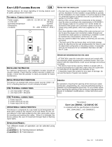
− The product does not have any type of isolating device for
the 230 Vac line. It will therefore be the responsibility of the
installer to arrange an isolating device inside the plant. It
must be positioned where it can be protected from accidental
closing, according to that prescribed in point 5.2.9 of EN
12453.
- Wiring of the various electrical components outside of the
product must be carried out in compliance with that pre-
scribed in Standard EN 60204-1 and its amendments at point
5.2.7 of EN 12453.
- For correct installation, follow these steps :
• Choose the point of flashing installation, payng attention to
get a good visibility of the light signal
Channeling the power cord in the 'special hole in the base of
the support. Use flexible cables sheathed in insulating
harmonized polychloroprene (H05RN-F) with a cross section of
1 mm2 and 1.5 mm2 and the outside diameter of between 7.3
mm and 8.3 mm.
• Use a cable tie or take appropriate steps to firmly anchor the
cable to the device.
• Attach the flashing beacon by means of screws or dowels
expansion.
• Remove with the 'help of a screwdriver the cover of
transparent material and the electronic circuit for easier wiring.
Appropriate action to remove a small piece of 'insulator
(stripping length 6mm) from the cable so as to facilitate the
insertion operation into the terminal card.
• Drill the hole on the base of the flashing light following the
track fitting .
• Insert the cable through the hole just made and run the elec-
trical wiring on the board as shown on the silkscreen.
• Plan and implement all precautions for installation which will
not affect the IP rating .
I
MPORTANT FOR THE INSTALLER
- ATTENTION: keep this instruction manual and respect the
important safety prescriptions contained herein. The non com-
pliance with the prescriptions may cause damages and serious
accidents.
- The device must never be used by children or persons with
reduced physical-psychological abilities, unless supervised or
trained on the functioning and the use modalities.
- Frequently examine the system to detect any signs of damag-
ing. Do not use the device if a repair intervention is necessary.
Attention
All operations which require the opening of the casing (cables
connection, programming, etc.) must be carried out by expert
personnel during installation. For any further operation which
requires the casing to be re-opened (replacement of LED
sources, maintenance, etc.) contact the after-sales assistance.
the product:
SMART LED 230VAC
is in compliance with the specifications of Directives
EMC 2004/108/EC, LVD 2006/95/EC.
LED Flashing beacon, for visual signalling of moving objects
such as gates, garage doors and more
T
ECHNICAL
D
ATA
- Power supply: 230V ac 50/60Hz 2W max.
- 2 x 1W LED : 2W Max.
- Working temperature: -10
÷
55°C
- Dimensions: 140 x 100 x 70 mm.
- Container: PMMA - ABS UL94V-0 ( IP44 )
I
NSTALLATION OF THE
F
LASHING BEACON
For excellent functioning, it is very important to choose the
place of installation carefully. Verify that the chosen surface is
capable of guaranteeing stable fixing. Verify that the chosen
position can be accessed easily for future maintenance opera-
tions.
I
NITIAL
O
PERATION
C
ONDITIONS
The device operate with 230Vac power sources; a flashing
electronic circuit is already included.
OPERATING FEATURES:
The flashing beacon is made of a transparent cap that protects
internal circuits and correctly diffuse light emitted by the LEDs,
and a base used for fixing it and passing cables. When the
device is active it warns the user that automation is in move-
ment using the luminous signals.
GB

2 Rev. 1.1 26/06/2014
/