Page is loading ...

Power source: DC 25-80V
Output current: <3A
Transmission power: <0.3mW
Working temperature: -15°C~+70°C
Protection level: IP20,Class 2
Installation sit: indoors, ceiling mounting
HF system: 5.8GHzCenter frequency CW electric wave,ISM band
Detection angle
: 360°(ceiling mounting)
Detection range
: 1-8m
(radii.) (adjustable)
18m Max.
(adjustable)(wall mounting)
Time setting
: 8sec-12min, (
adjustable
)
Light-control
: 10-1000LUX, (
adjustable
)
Specifications
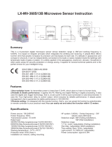
LX-MV-360S10MD-B Microwave Sensor Instruction
Summary
Features
LX-MV360S10MD-B is a hi-precision digital microwave sensor whose detection range is 360°and working
frequency is 5.8GHz. It applies Doppler principle to emit & receive signals. It adopts MCU (Micro Control Unit)
that greatly increases its precision and decreases its fault rate. It’s delicate in appearance and compact in
structure. It can be independently connected to the loads or easily installed inside the lightings with the
non-metal lampshade. It is widely applied in the passageway, washroom, elevator, household or other public
areas for security protection or energy saving. It possesses several technical patents and is the perfect choice
for your intelligent living.
1.Non-radiation harm: its transmitter power is less than 0.3mW, which does no harm to human body.
2.LED specialized dimmable sensor: auto start dimming mode at night without motion signal; auto exit when
ambient light is over 100 lux.
3.Percentage dimmable range: 0%~10%.
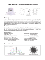
Sensing distance adjustment range
Sensor information
LED DC
25~80V
+
-
+
-
+
-
+
-
SENS
LUX
TIME
DIM
22 44 66 8810
m
24 6 8 10
m
10
m
0°
10°
20°
30°
40°
50°
60°
70° 80° 90° 100° 110° 120°
130°
140°
150°
160°
170°
180°
190°
200°
210°
220°
230°
240°
250°
260°
270°
280°
290°
300°
310°
320°
330°
340°
350°
1
2
3
4
5
6
7
8
9
11
12
012345678910 10987654321
10
Detection range: 8m max (Height of installation2.5m) Detection range: 8m max (Height of installation4m)
Detection range: 7m max (Height of installation8m)
Detection range: 7m max (Height of installation6m)
Detection range: 7m max (Height of installation10m)
Ceiling installation
92mm
23.5mm
33mm
74.5mm
84mm
H
L L
Ground

LED DC 25~80V
+
-
+
-
+
-
+
-
SENS
LUX
TIME
DIM
LED indicator Light Sensr
Applications
Microwave can penetrate the glass, plastic and wood, thus the microwave sensor can be installed inside the
non-metal shade. For example, the application in LED lightings, only if making connection as below shown can
you change the common LED lightings into auto-sensing ones.
LED “+” “-”: connect to LED panel
DC“+” “-”: connect to DC power (DC 25~80V)
LED drive power requirements: Output voltage range is between 25~80V, constant power supply with power
within 100W.
Notice: Due to the sensor is connected with driver power output and use PWM to adjust light, so it has
special requirements of driver power supply mode.Commonly installed with current sampling LED driver. If the
light worked unstable or in low brightness ,it is due to the LED driver not matched with sensor. So the user
must choose the appropriate driver with sensor.
If you found the brightness of light is going light up and decline slowly or have strobe phenomenon in low
brightness during the testing.This is not a problem from sensor,it’s due to the driving power not matched with
sensor,please replace the driver to solve the situation.
How to make connection:
Warning!
Microwave will be reflected by the metal, thus
the microwave sensor cannot be installed
inside the shade made of metal, or it won’t
work normally.
+
-
+
-
DC 25~80V
LED panel
LED driver
25~80V/ within100W AC
Setting manner one:potentiometer
It may take times to adjust values before they satisfy your need.
Pay attention!
Keep slow when turning the potentiometers, during this process, it will auto-compute the exact function
following the adjustment. Otherwise, you will miss the perfect function to the adjustment.
LED indicator:
(1) When you perform any adjustment of potentiometers, LED indicator lights on.
(2) When you perform any adjustment of potentiometers, 1 second after finishing adjustment LED indicator
flashes twice and be off, then the system will memorize and auto-compute the exact function to the adjustment.
1-6m
Correct moving orientation Detection angle
18m Max 180°
Height of installation1-6m
Wall installation

(2)Detection range setting(sensitivity)
Detection range is the term used to describe the radii of the roughly circle casting on the
ground when installed at the height of 2.5 m. To turn fully anti-clockwise is the minimum
distance (approx. 1m), fully clockwise is the maximum (approx. 8m). If person’s stature,
figure and moving speed change, the detection will also change, that is, the higher
speed will lead to the shorter detection distance.
Notice: when using this product, please adjust the sensitivity (detection range) to an
appropriate value but the maximum to avoid the abnormal reaction caused by the easy
detection of the wrong motion by the blowing leaves & curtains, small animals or the
interference of power grid & electrical equipment. All the above mentioned will lead to the
error reaction. When the product does not work normally, please try to lower the sensitivity
appropriately, and then test it.
1-8m
+-
SENS
10-1000LUX
LUX
DIM
(3)Light-control setting
It can be defined in the range of 10~1000 LUX. To turn fully anti-clockwise is about 10
lux, fully clockwise is about 1000 lux. You are supposed to turn fully clockwise during
the daytime walking test or adjustment of detection range, in this case, the LED lamp
controlled will keep on however the ambient light is.
(4)Percentage dimmable lighting
It can be defined in the range of 0%~10%. When the ambient light is less than 70 lux,
the system starts dimming mode. If there is no signal detected during the delay time, it
will enter the percentage lighting. Once signal detected, it recovers to 100% lighting. It
will auto exit dimming mode, when the ambient light is over 100 lux. The dimming mode
works digitally and independently.
(1)Time setting
When motion signal detected, the LED lamp controlled be auto on. And if there is no
signal during the delay time (8s ~12min), it be auto off and you’re expected to wait for 4
seconds before the next detection. And any motion signal detected during the
customer-defined time will lead the system re-compute the time. It is suggested you
choose the minimum time during test to save energy & time.
8sec-12min
+-
TIME
LED DC 25~80V
+
-
+
-
+
-
+
-
SENS
LUX
TIME
DIM
LED indicator Light Sensr
LED DC 30~100V
+
-
+
-
+
-
+
-
SENS
LUX
TIME
DIM

Fault and the solution
The load fails to work.
Light-illumination is set incorrectly.Adjust the setting of the load.
Change the load.
Turn the power on.
Change the suitable
LED driver.
Check the settings of the
detection area.
The load is broken.
The power is off.
There is a continuous signal in the region of the detection.
LED driver fails to meet the requirements.
The motion speed is too fast or or the motion direction is wrong.
Fault Failure cause Solution
The load works all the time.
The load works when there is
no motion signal detected.
Lamplight flashes when start or
exit dimming mode
Change the motion direction or speed.
There are disturbing signals around.
Check if there are moving
objects caused by the blowing wind.
● Please confirm with prefessional installation.
● For safety purposes, please cut off power before installation and removal operations.
● Any losses caused by improper operation,the manufacturer does not undertake any
responsibility.
Warning!
We are committed to promoting the product quality and reliability, however, all the electronic
components have certain probabilities to become ineffective, which will cause some
troubles.When designing, we have paid attention to redundant designs and adopted safety
quota to avoid any troubles.
This instruction, without our permission, should not be copied for any other purposes.
Warning!
1、Being installed on the rocking object will lead to error reaction.
2、The shaking curtain blown by wind will lead to error reaction. Please select the suitable place to install.
3、Being installed where the traffic is busy will lead to error reaction.
4、The sparks produced by some equipment nearby will lead to error reaction.
The following situations will lead to error reaction.
/