Page is loading ...

Power source: 100-240VAC
Power frequency: 50Hz
Transmission power: <0.3mW
Rated load:
2400W/10A,Max,tungsten(cosφ=1)(220-240VAC)
1500W/8A,Max,fluorescent(cosφ=0.5)(220-240VAC)
1200W/10A,Max,tungsten(cosφ=1)(100-130VAC)
800W/8A,Max,fluorescent(cosφ=0.5)(100-130VAC)
Working temperature: -15°C~+70°C
Protection level: IP20,Class 2
Installation sit: indoors, ceiling mounting
HF system: 5.8GHz
Center frequency
CW electric
wave,ISM band
Detection angle
: 360°
Detection range
: 1m-3m-6m-11m
(radii.) (adjustable)
Time setting
: 8sec-1min-5min-12min, (
adjustable
)
Light-control
:
10LUX-50LUX-200LUX-1000LUX, (
adjustable
)
Power consumption: approx.0.5W
Specifications
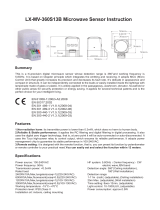
LX-MV-360S12A Microwave Sensor Instruction
Summary
Features
This is a hi-precision digital microwave sensor whose detection range is 360°and working frequency is
5.8GHz. It is based on Doppler principle which integrates the emitting and receiving. It adopts MCU (Micro
Control Unit) that greatly increases its precision and decreases its fault rate. It’s delicate in appearance and
compact in structure. It can be independently connected to the loads or easily installed inside the lightings with
lampshade made of glass or plastic. It is widely applied in the passageway, washroom, elevator, household or
other public areas for security protection or energy saving. It applies for several technical patents and is the
perfect choice for your intelligent living.
1.Non-radiation harm: its transmitter power is lower than 0.3mW, which does no harm to human body.
2.Reliable & Stable performance: it applies the RC filtering and digital filtering in digital processing. It also
uses the digital zero trigger technology, that is, at zero point it will be auto-connected or auto-disconnected. It
uses the Tyco high-power relay to control output, which ensures its reliable performance. It adopts power
management chip to guarantee its stable performance in 100-240V/AC.
3.Remote setting: it is designed with the remote function, that is, you can preset its function by DIP switch or
remote controller to your practical need.
4.Slowly on and off: it is added with PWM controlled optical coupler working with the specialized controlled
power to achieve the slowly on and off, that is, when signal detected, the light controlled will be slowly on and
will be slowly off if there is no signal detected during the preset delay time. It protects human from the unfitness
caused by the sudden light or darkness.
EN 61058-1:2002+A2:2008
EN 50317:2002
EN 301 489-1 V1.8.1(2008-04)
EN 301 489-3 V1.4.1(2002-08)
EN 300 440-1 V1.5.1(2009-03)
EN 300 440-2 V1.3.1(2009-03)

L’
L’
L N
L
N
IN
VCC
+
-
L’ L N
Applications
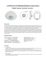
The above application inside the lightings is one of multiple practical utilizations. You can also install one or more inside
the ceiling or floor to control the whole passageway.
Friendly reminder: when installing two or more microwaves together, you are required to keep 4 meters one from
another, otherwise the interference among them will lead to error reaction.
Load type
Security alarming system
CFL Energy-saving lamp
Pure resistive load
Microwave can penetrate the glass, plastic and wood, thus the microwave sensor can be installed inside the
shade made of certain thickness of glass, plastic or wood. For example, the application in lightings, only if
making connection as below shown can you change the common lightings into auto-sensing lightings.
< Connect N, L with power;Connect N, L’ with load. >
Connection mode one:
LED Light source
Fluorescent lamp
Warning!
Nonmetals
When installed inside the ceiling or floor, the microwave sensor
fails to distinguish the ambient light intensity automatically.
Connection mode two:
Adjustable light ballast
Fluorescent tube
AC
L
L’
N
Microwave will be reflected by the metal, thus
the microwave sensor cannot be installed
inside the shade made of metal, or it won’t
work normally.
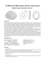
2.5-4.5m
360º
Min:1mMin:1m Max:11mMax:11m
Height of installation2.5-4.5m Sensing angle adjustment range Sensing distance adjustment range
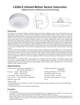
Sensor information

TIME:S3,S4
LUX:S1,S2
S1 S2 Light-control
0 0 10LUX
0 1 50LUX
1 0 200LUX
1 1 1000LUX
1
0
S3 S4 Time setting
0 0
12min
0 1
5min
1 0
1min
1 1
8s
1
0
(1)Light-control setting
It can be defined in the range of 10~1000 LUX. To set the
switch to ON is “1”, to OFF is “2”. Read through the right
shown the corresponding table of the switch position to
the light-control value.
(2)Time setting
It can be defined from 8 seconds to 12minute. Any
movement detected before this time elapse will re-start
the timer. It is recommended to select the shortest time for
adjusting the detection range and for performing the walk
test. To set the switch to ON is “1”, to OFF is “2”. Read
through the right shown the corresponding table of the
switch position to the delay time.
It is mainly for the adjustment of the delay time from the moment the signal detected and light
auto-on till the light auto-off. You can define the delay time to your practical need. But you’d
better lower the delay time for the sake of energy saving, since the microwave sensor has the
function of continuous sensing, that is, any movement detected before the delay time
elapses will re-start the timer and the light will keep on only if there is human in the detection
range.
SENS:S5,S6
S5 S6
0 0 1m
0 1 3m
1 0 6m
1 1 11m
1
0
Detection range
(3)Detection range setting (sensitivity)
Detection range is the term used to describe the radii of the
roughly circle casting on the ground when installed at the
height of 2.5 m. To set the switch to ON is “1”, to OFF is
“2”. Read through the right shown the corresponding table
of the switch position to the detection range.
Notice: when using this product, please adjust the sensitivity (detection range) to an
appropriate value but the maximum to avoid the abnormal reaction caused by the easy
detection of the wrong motion by the blowing leaves & curtains, small animals or the
interference of power grid & electrical equipment. All the above mentioned will lead to the
error reaction. When the product does not work normally, please try to lower the sensitivity
appropriately, and then test it. Human movement will cause the sensor induction,so when
you under the function testing,please leave the induction region and don't make movement
to prevent the sensor continuous work.
Friendly reminder: when installing two or more microwaves together, you are required to
keep 4 meters one from another, otherwise the interference among them will lead to error
reaction.
LUX:S1,S2 TIME:S3,S4 SENS:S5,S6
1
0
Setting manner one:DIP switch
As below shown, by S1,S2 to set the light-control value, S3,S4 the delay time, S5,S6 the detection range. It
may take times to adjust values before they satisfy your need.

Warning!
1、Being installed on the rocking object will lead to error reaction.
2、The shaking curtain blown by wind will lead to error reaction. Please select the suitable place to install.
3、Being installed where the traffic is busy will lead to error reaction.
4、The sparks produced by some equipment nearby will lead to error reaction.
The following situations will lead to error reaction.
● Please confirm with prefessional installation.
● For safety purposes, please cut off power before installation and removal operations.
● Any losses caused by improper operation,the manufacturer does not undertake any
responsibility.
Warning!
We are committed to promoting the product quality and reliability, however, all the electronic
components have certain probabilities to become ineffective, which will cause some
troubles.When designing, we have paid attention to redundant designs and adopted safety
quota to avoid any troubles.
This instruction, without our permission, should not be copied for any other purposes.
Fault and the solution
The load fails to work.
Light-illumination is set incorrectly.Adjust the setting of the load.
Change the load.
Turn the power on.
Check the settings of the
detection area.
Re-adjust the installation place.
Check the settings of the
detection area.
Check the settings of the
detection area.
The load is broken.
The power is off.
There is a continuous signal in the region of the detection.
Moving signal is detected by the sensor (movement
behind the wall, the movement of small objects, etc.)
The lamp isn't installed well so that sensor fails to
detect reliable signals.
The motion speed is too fast or the defined detection
area is too small.
Fault Failure cause Solution
The load works all the time.
The load works when there is
no motion signal detected.
The load fails to work when
there is motion signal detected.
Setting manner two:Remote control
①
SENS
ON: press ON, the load connected will keep working for 6 hours
and then automatically turn to AUTO mode.
OFF: press OFF, the load connected will be off for 6 hours and
then automatically turn to AUTO mode.
AUTO: press AUTO, sensor enters the auto-detecting mode,
that is, when signal detected and the ambient light intensity is
lower than the preset value, the load works.
Friendly reminder: there are two manners to define its function and the last definition will be
effective and still be valid even if the sensor restarts.
/