Page is loading ...

SWC-61
COMMERCIAL AIR CONDITIONERS SDV6
USER & INSTALLATION MANUAL

This manual gives detailed description of the precautions
that should be brought to your attention during operation.
In order to ensure correct service of the wired controller
please read this manual carefully before using the unit.
For convenience of future reference, keep this manual after
reading it.
CONTENTS
1
About the documentation
For the user
1.2
1.1 01
02
Installation Precautions
Installation Method
4.2
4.1 06
08
GENERAL SAFETY PRECAUTIONS
205
BASIC PARAMETERS
305
ACCESSORIES LIST
406
INSTALLATION

Control Panel Explanation
5.1 16
5 OPERATION INSTRUCTIONS
17
18
30
Display Explanation
Operation Instructions
Mode Conflict Prompt
Project Commissioning
5.3
5.4
30
5.5
5.2

1 GENERAL SAFETY PRECAUTIONS
1.1 About the documentation
The original documentation is written in English. All other
languages are translations.
The precautions described in this document cover very
important topics, follow them carefully.
All activities described in the installation manual must be
performed by an authorized installer.
1.1.1 Meaning of warnings and symbols
Indicates a situation that results in death or serious
injury.
DANGER: RISK OF ELECTROCUTION
Indicates a situation that could result in electrocution.
DANGER: RISK OF BURNING
Indicates a situation that could result in burning
because of extreme hot or cold temperatures.
DANGER
01

1.2 For the user
If you are not sure how to operate the unit, contact your
installer.
Indicates a situation that could result in death or
serious injury.
Indicates a situation that could result in minor or
moderate injury.
Indicates a situation that could result in equipment or
property damage.
Indicates useful tips or additional information.
WARNING
CAUTION
NOTE
INFORMATION
i
02

The appliance is not intended for use by persons, including
children, with reduced physical, sensory or mental
capabilities, or lack of experience and knowledge, unless
they have been given supervision or instruction concerning
use of the appliance by a person responsible for their safety.
Children must be supervised to ensure that they do not play
with the product.
Do NOT rinse the unit. This may cause electric shocks
or fire.
Do NOT place any objects or equipment on top of
the unit.
Do NOT sit, climb or stand on the unit.
CAUTION
NOTE
03

Units are marked with the following symbol:
This means that electrical and electronic products may not be
mixed with unsorted household waste. Do not try to dismantle
the system yourself: the dismantling of the system, treatment of
the refrigerant, of oil and of other parts must be done by an
authorized installer and must comply with applicable
legislation. Units must be treated at a specialized treatment
facility for reuse, recycling and recovery. By ensuring this
product is disposed of correctly, you will help to prevent
potential negative consequences for the environment and
human health. For more information, contact your installer or
local authority.
04

2 BASIC PARAMETERS
3 ACCESSORIES LIST
DescriptionItems
Rated voltage
Wiring size
Operating environment
Humidity
DC18V
-5°C ~ 43°C
≤ RH90%
05
No.
1
2
3
Name
Wired controller
Philips head screw, M4×25
Installation and Operation Manual
Quantity
1
2
1
5Bottom cap of the wired controller 1
4Plastic support bar 2
6 Round head screw ST4X20 3
7Plastic expansion pipe 3
RVVP-0.75mm2×2

4.1 Installation Precautions
Entrust a local distributor or local service agent to
appoint a qualified technician to perform the
installation. Do not try to install the unit by yourself.
Do not knock, throw, or randomly disassemble the
wired controller.
The wiring must be compatible with the wired
controller current.
Use the specified cables, and do not place any heavy
object on the wiring terminals.
The wired controller line is a low-voltage circuit, which
cannot come into direct contact with the high voltage l
● To ensure correct installation, read the "Installation" section
of this manual.
● The content provided here covers warnings, which contain
important information about safety that must be followed.
4 INSTALLATION
06
CAUTION

ine or be laid in the same wiring tube together with the
high voltage line. The minimum spacing of wiring
tubes is 300 to 500 mm.
Do not install the wired controller in corrosive,
flammable and explosive environments or places with
oil mist (such as a kitchen).
Do not install the wired controller in a wet place and
avoid direct sunlight.
Do not install the wired controller when it is powered
on.
Please install the wired controller after painting the
wall; otherwise, water, lime and sand may enter the
wired controller.
07

08
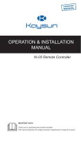
4.2 Installation Method
4.2.1 Wiring requirements
One-to-more and two-to-more
Please use the shielded wire, and
the shield layer must be grounded.
The IDU can realize the one-to-more and
two-to-more functions.
(main-secondary wired controller needs
to be set)
D1 D2 D1 D2
D1 D2
X1 X2
Wired
controller
X1 X2
Wired
controller
X1 X2
CN6
CN2 CN2 CN2
IDU 16#
IDU 1# IDU 2#
IDU 3-15#
L3 Ln
L1 L2
Please use shielded wires, and the
shield layer cannot be grounded.
The one-to-more function must be set for the wired controller.
After the communication between the wired controller and
IDU lasts 3 minutes and 30 seconds, the control can be
implemented.
···

09
P/Q/ E P/Q/ E P/Q/ E
P/Q/ E
X1/X2
One-to-one One-to-one One-to-one
One-to-one
X1/X2 X1/X2
● Applicable to bi-directional communication between wired
controller and IDU.
● One-to-one: One wired controller controls one IDU. The
parameters displayed on the wired controller are updated in
real time according to changes in the parameters of the IDU.
● The permissible longest wiring length of the system is 200 m.
● Communication cables between the IDU and the wired
controller (X1, X2) may be connected in reverse order.

10
Applicable to bi-directional communication between wired controller
and IDU.
Two-to-one: Two wired controller controls one IDU. The parameters
displayed on the wired controller are updated in real time according
to changes in the parameters of the IDU.
Two-to-one:wired controller must be set as main or secondary.
Refer to "Parameter settings C00"
The permissible longest wiring length of the system is 200 m.
Communication cables between the IDU and the wired controller
(X1, X2) may be connected in reverse order.
Two-to-one
P/Q/E P/Q/E P/Q/E
P/Q/E
X1/X2
Not allow
○○○
X1/X2 X1/X2X1/X2 X1/X2

When installed on 86 Electrician box:
Adjust the lengths of the two plastic support bars in the
accessory package. Ensure that the bottom cap of the wired
controller stays level with the wall when installed on the screw
post of electrical box. Use a cutting tool to
adjust the lengths of the
two plastic support bars
4.2.2 Installlation of bottom cap of the wired controller
11
Screw hole
installed on 86
Electrician box,
use two Philips
head screw,
M4×25
Screw hole
installed on
the wall Use
three round
head screw
ST4X20 and
plastic
expansion
pipe
Screw post of
the electrical
box

4.2.3 Lead the 2-core shielded cable through the wiring
hole in the bottom cap of the wired controller, and use
screws to reliably fasten the shielded cable onto
terminals X1 and X2. Then fix the bottom cap of the wired
controller onto the electrical box by using pan head
screws.
12
Cutting place of up,downleft
and right side wire outlet
Up down left and right side wire outlet
When installed on the wall:
The wire can be placed outlet or inside. Wire outlet have
four side to select.

Do not overtighten the pan head screws; otherwise,
the bottom cap of the wired controller may deform and
cannot be levelled on the wall surface, which makes it
difficult to install or not securely installed.
Do not perform wiring operations on energized parts.
Make sure that you remove the wired controller before
proceeding. Otherwise, the wired controller may be
damaged.
13
NOTE

Avoid the water enter
into the wired remote
controller, use trap
and putty to seal the
connectors of wires
during wiring
installation.
86Electrician box wire outletwire inside
4.2.4 Buckle the wired controller and the rear cover as
shown in the following figure.
14

Make sure that no cables are clamped when buckling
the wired controller and bottom cap.
The wired controller and bottom cap should be
installed correctly. Otherwise, they may get loose and
fall apart.
When they are correctly buckled
15
NOTE

5.1 Control Panel Explanation
5 OPERATION INSTRUCTIONS
Auto
Cool
Fan
Heat
Dry
No permission Hold recheck AU-heat
Set
Temp Humidity
Self
Clean
Hold
Hold Cancel
self clean SYS. Diag
OFF/ON
Later OFF/ON
Auto Swing
Sterilize
Comfor air
adjust
Auto
Fan
AC OFF
M
On/OffFan speed/sleep
Operating
indicator
Fan directionFan speed Adjustment
button
TimerMode
Remote
signal
receiving
area
Operating
mode
Fan
direction
Timer
16

5.2 Display Explanation
NO.
Icon Name Description
It will be flashed when IDU energy efficiency
attenuated.When "Parameter settings C17" is
seted "yes",the screen displays IDU Energy
1Attenuation
Energy Efficiency
w
Ef
i
f
r
i
e
c
d
ie
c
n
o
c
n
y
t
A
ro
t
l
t
l
e
e
n
r
u
is
at
in
ion
off
pe
m
r
o
ce
d
n
e
ta
.E
g
f
e
fic
w
ie
h
n
e
c
n
y
the
Attenuation percentage and filter blockage
percentage will be displayed alternately in off
mode when "Parameter settings C17 and
C18" are seted “yes”.
2 Sleep Mode
It will be lighten when the unit is in sleep mode
3ETA
It will be lightened when the ETA
Function
Function is activated.
4Key Lock
Refer to page 24
5Defrosting Mode
Refer to page 24
6Lock Mode
It will be lightened when the mode of
controller is locked.
7Backup Mode
It will be flashed when IDU in backup state.
8Filter Blockage
Refer to page 25
9
M
Main/secondary
a
It
s
w
t
i
h
ll
e
b
m
e
a
lig
in
ht
c
e
o
n
n
e
tr
d
o
w
lle
h
r
en the controller is set
17
/