Page is loading ...

Home » SELTRON » SELTRON AVD Motor Actuator User Manual
Contents
1 SELTRON AVD Motor Actuator
2 Introduction
3 Product installation
4 Electrical connection and setting
4.1 MODULATING ACTUATOR 24V AND 230V
5 Manual operating mode
6 Removing old electrical and electronic
equipment
7 Technical data
8 Documents / Resources
8.1 References
9 Related Posts
SELTRON AVD Motor Actuator
SELTRON AVD Motor Actuator User Manual
Manuals+ — User Manuals Simplified.

Introduction
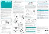
1. Button for mounting and dismounting the actuator on the valve.
2. Actuator operation indicator.
Rotating the actuator counterclockwise.
The light illuminates at half brightness when the motor actuator is in end position.
Rotating the actuator clockwise.
The light illuminates at half brightness when the motor actuator is in end position.
The clutch is activated
Status of additional switch and modulating actuator. The status has several states:
The green light is on. The actuator is operating normally.1
The green light flashes. No signal / broken control line.1 (Only available when 2-10 V or 4-20 mA control signal
is selected).1

The red light is on. The additional switch is activated.2
The red light flashes. The actuator cannot overcome the load of the valve.1
The red light flashes every 5 seconds. A valve blockage was detected but is no longer present.1 The display is
reset by pressing the button or by restarting the power supply of the motor actuator.
1. Button to set the actuator opening direction.2
2. Button to set the actuator operating mode.1
3. Scale to set the valve position display.
4. Mixing valve manual positioning button.
5. Ring for additional switch.3
6. Button (clutch) for manual operation mode.
Only for modulating actuators.
Only for modulating and 2-point actuators with or without additional switch.
Only for 2- and 3-point actuators with additional switch.
Warnings
Installation and electrical connection should only be carried out by a person with suitable qualification. When
installing, it is necessary to follow the rules of the profession, valid legislation and regulations. When installing,
make sure that the actuator is mounted away from open sources of fire or water. If there is a possi-bility of
flooding, the actuator must be installed above the possible level of the flood water level. Any interference with the
actuator not described in the manual is forbidden. Before installing the actuator, make sure that the parts in
contact with the actuator and the installer are not under voltage. The operator or the system user is responsible
for the selection of a qualified person that will perform the installation of the actuator. The user is also responsible
for the proper operation and maintenance of the system.
Failure to follow the instructions and unprofessional work may result in the following:
actuator malfunction
endangering the safe operation of the system
damage to the system
risk of electric or mechanical shock for persons in contact with the system
Product installation
1. Turn the valve to the middle position or to the middle between open and closed positions. Remove the manual
positioning button from the valve axis and screw on the actuator axis adapter.
2. Tighten the locking screw to the intended location on the valve.
3. On the actuator, press the actuator mount button and plant it on the valve axis. Remove the manual positioning

button and the scale ring from the actuator. Use a flathead screwdriver to remove the ring. Set the ring for the
scale or the direction of opening and closing the valve and return it to the actuator. Lastly, return the manual
positioning button. Disassemble the actuator by holding down the button for mounting the actuator and pulling it
from the valve.
Electrical connection and setting
2- AND 3-POINT ACTUATOR WITH OR WITHOUT ADDITIONAL SWITCH

Adjusting the position of the additional switch 4
To turn on the additional switch, press the button and turn the manual positioning button to the position
where the additional switch is to be activated. Press the button again and remove the manual positioning
button. By rotating the ring for the additional switch, set the activating point of the additional switch. Align one of
the two indicators separating the ON and OFF fields on the ring with the triangular mark on the motor actuator
cover. In the ON field, the additional switch is activated, in the OFF field, the additional switch is deactivated. After
the setting, return the manual positioning button back to the actuator.
4 Only for 2- and 3-point actuators with additional switch. 5 Unavailable.
Setting the valve opening direction
The direction of opening the valve is set with the button
The symbol means opening counterclockwise.
The symbol means opening clockwise.
MODULATING ACTUATOR 24V AND 230V

Remove the manual valve positioning button before starting the setup.
Setting the valve opening direction
The direction of opening the valve is set with the button
The symbol means opening counterclockwise.
The symbol means opening clockwise.
Setting the operation of the actuator with a supply voltage of 24 V
The operation of the actuator is set by selecting the function or combination of control signal and actuator speed.
The desired mode of operation is selected with the button
The combination of control signal and actuator speed is described in the table.
Setting the operation of the actuator with a supply voltage of 230 V
The operation of the drive is set by selecting the function or control signal with the button . Possible control
signals are described in the table.
After the settings, return the manual positioning button back to the actuator.
Manual operating mode
To activate the manual operating mode, press the button. . The LEDs on the actuator and are on. Now you can
turn the valve to any position by turning the manual positioning button. Switch off manual operation by pressing
the button .
Removing old electrical and electronic equipment
Disposal of old electrical and electronic equipment (Applies to the Member States of the European Union and
other European countries with a separate waste collection system). This symbol on the product or packaging
marks that it should not be discarded as household waste. It needs to be taken to a collection point for waste
electrical and electronic equipment (WEEE). Suitable disposal of this product prevents negative effect on the
environment and health which could otherwise be caused by its unsuitable disposal. Recycling of material
reduces usage of new raw materials. For more information on recycling of this product, contact the competent
authorities, municipal service or the store where you purchased the product.

/